manuals.online logo
Brands
  1. Home
  2. •
  3. Brands
  4. •
  5. Oris
  6. •
  7. Automobile Accessories
  8. •
  9. Oris 38.380-1932 Install guide

Oris 38.380-1932 Install guide

This manual suits for next models

2

Other Oris Automobile Accessories manuals

Oris 044-721 Install guide

Oris

Oris 044-721 Install guide

Oris 048973 User manual

Oris

Oris 048973 User manual

Oris 022701 Install guide

Oris

Oris 022701 Install guide

Oris 022631 Install guide

Oris

Oris 022631 Install guide

Oris 037-181 Install guide

Oris

Oris 037-181 Install guide

Oris 049-213 Install guide

Oris

Oris 049-213 Install guide

Oris 049943 User manual

Oris

Oris 049943 User manual

Oris 034543 Install guide

Oris

Oris 034543 Install guide

Oris Tourer User manual

Oris

Oris Tourer User manual

Oris 049-213 Install guide

Oris

Oris 049-213 Install guide

Popular Automobile Accessories manuals by other brands

Magneti Marelli AC161 Installation instruction

Magneti Marelli

Magneti Marelli AC161 Installation instruction

FDI uEZ GUI Start here

FDI

FDI uEZ GUI Start here

JCROffroad JT Install instructions

JCROffroad

JCROffroad JT Install instructions

Rostra VOXXElectronics 250-1930 owner's guide

Rostra

Rostra VOXXElectronics 250-1930 owner's guide

TOP VEHICLE TECH GR3FORD5 installation manual

TOP VEHICLE TECH

TOP VEHICLE TECH GR3FORD5 installation manual

Safe Fleet PRIME DESIGN AR-2000-BLK manual

Safe Fleet

Safe Fleet PRIME DESIGN AR-2000-BLK manual

Skoda Fabia Combi 5J Fitting instructions

Skoda

Skoda Fabia Combi 5J Fitting instructions

Camcar 40077 Al Mounting instructions

Camcar

Camcar 40077 Al Mounting instructions

Camcar 40089 AL Mounting instructions

Camcar

Camcar 40089 AL Mounting instructions

Impac Tradesman 2000 installation manual

Impac

Impac Tradesman 2000 installation manual

DVB OFFROAD BRSB-01 installation manual

DVB

DVB OFFROAD BRSB-01 installation manual

Safari Snorkel SS385HF installation guide

Safari Snorkel

Safari Snorkel SS385HF installation guide

ULTIMATE SPEED 279746 Assembly and Safety Advice

ULTIMATE SPEED

ULTIMATE SPEED 279746 Assembly and Safety Advice

SSV Works DF-F65 manual

SSV Works

SSV Works DF-F65 manual

ULTIMATE SPEED CARBON Assembly and Safety Advice

ULTIMATE SPEED

ULTIMATE SPEED CARBON Assembly and Safety Advice

Witter F174 Fitting instructions

Witter

Witter F174 Fitting instructions

WeatherTech No-Drill installation instructions

WeatherTech

WeatherTech No-Drill installation instructions

TAUBENREUTHER 1-336050 Installation instruction

TAUBENREUTHER

TAUBENREUTHER 1-336050 Installation instruction

manuals.online logo
manuals.online logoBrands
  • About & Mission
  • Contact us
  • Privacy Policy
  • Terms and Conditions

Copyright 2025 Manuals.Online. All Rights Reserved.

1/14
Montagehandleiding
Fitting instruction
Montageanleitung
Description de montage
Instrucciones de montaje
Montagevejledning
Monteringsvejledning
Monteringshandledning
Asennusohje
Istruzioni di montaggio
Návod k montáži
Szerelési utas tás
Порядок установки
Mazda 6 HB & Lim. & Estate
2008  2012
Type Nr.: 036-391
Order Nr.: 036-401
Ball code: 38.380-1932
EC 94/20
e7 00-0148
2075 kg
1800 kg
75 kg
D
Waarde
Value
Wert
Valer
Érték
10,0
kN
NL D GB N SF I F
E DK S CZ H RU PL
© ACPS
Automotive
HUK issue: 15.02.2020
Rev.Nr.: 07
9. 2x M12x70 (10.9)
10 8x M12x50
12. 10x M12
 Raadpleeg uw dealer voor de max. massa die uw wagen mag trekken.
 ie maximale Anhängelast ihres Fahrzeuges können Sie im Fahrzeugschein oder im
Benutzerhandbuch nachlesen.
 For the max. trailer weight of your car please refer to the owner's manual or your car
homologation documents.
 Pour connaître le poids maxi remarquable pour votre voiture consulter la notice
d'utilisation de votre voiture ou la carte grise.
 Consulte a su distribuidor sobre el peso máximo que puede remolcar su vehículo.
 eres forhandler vil kunne oplyse em om den højst tilladte vægt efter eres køretøj.
 Ta kontakt med forhandleren angående den maksimale vekt som bilen kan trekke.
 Se handboken eller registreringsbevis för max släpvagnsvikt för din bil.
 Tarkista suurin sallittu vetopaino ajoneuvon ohjekirjasta tai rekisteriotteesta.
 Per conoscere il peso massimo rimorchiabile dalla propria autovettura, fare riferimento al
manuale d'istruzione od ai documenti di omologazione della vettura stessa.
 Maximální přípustná hmotnost přívěsu pro Vaše vozidlo je uvedena v technickém
průkazu nebo v uživatelské příručce.
 A maximális vontatható tömegekről győződjön meg a gépkocsi kezelési könyvéből, vagy
a gépkocsi típusbizonyítványából.
 Максимальную массу прицепа просим проверять в заводской книжке или по в
типовом сертификате автомобиля.
Meegeleverde onderdelen
Piezas incluidas
Mukana tulevat osat
Mitgelieferte Befestigungsteile Medfølgende komponenter Componenti forniti a corredo
Provided parts Vedlagt festemateriell odané upevňovací díly
Materiel de fixation joint Medföljande komponenter Tartozékjegyzék
Список комлектующих
11. 8x M12
13. 2x M12 (10)
2/14
3/14
4/14
5/14
6/14
7/14
(CZ) 036-401 Návod k montáži:
1. Podle přiloženého seznamu zkontrolovat jednotlivé součásti tažného
zařízení. Pokud je to nezbytné, odstranit ze styčných bodů v zavazadlovém
prostoru ochranný prostředek
2. Odmontujte zadní světla, nárazník a nárazníkovou výztuž (tu už v budoucnu
nebudete potřebovat).
3. Nalakujte místo nosníku nárazníkové výztuže.
4. Odvěste buben výfuku ze zadního i předního gumového kozlíku, spusťte ho
níže a tak podepřete buben výfuku.
5. Odsuňte tepelný štít, abyste se dostali k vnější straně podvozkového trámu
a poté ze dvou otvorů na boku podvozkového rámu odstraňte ochrannou
lepící pásku.
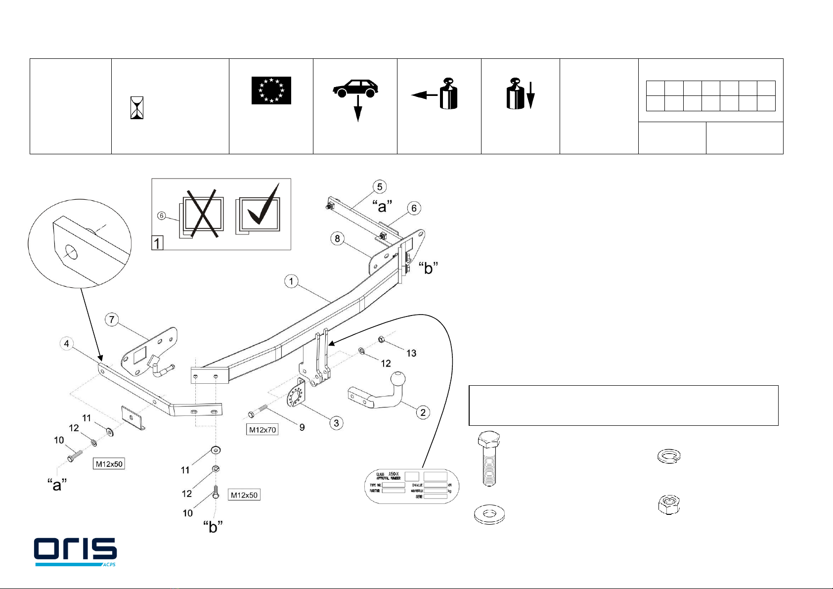
6. eštičky držící výfuk (7,8) umístěte na jejich místo na pravé i levé straně a
připevněte je šrouby z odstraněné nárazníkové výztuže.
7. o podvozkového trámu umístěte pravou i levou postranní desku (4,5),
které pak v bodech „a” volně připevněte pomocí přiložených spojovacích
elementů tak, jak to uvádí výkres. bejte na to, aby díl (6) přesně dosedl na
dno podvozkového trámu, viz. obr. 1.
8. Těleso tažného zařízení (1) volně upevněte pomocí přiložených spojovacích
prvků v bodech „b”, tak jak to uvádí výkres.
9. Tažné zařízení nastavte do středové polohy a fixně dotáhněte všechny
šrouby:
M12 (10.9) 117 Nm
M12 (8.8) 79 Nm
10. Vystřihněte nárazník podle přiložené výstřihové šablony.
11. Na těleso tažního zařízení namontujte těleso koule (2) a desku držící
zásuvku (3).
12. Namontujte zpět všechny součástky, které byly během montáže odstraněny
(s výjimkou nárazníkové výztuže).
13. Po ujetí zhruba 1000 km dotáhnout všechny šrouby a matice na výše
uvedené hodnoty točivého momentu.
14. Firma ACPS Automotive nenese zodpovědnost za jakoukoliv závadu na
výrobku způsobenou nesprávným zacházením na straně uživatele nebo
osoby za kterou je zodpovědný.
15. Montáž tažného zařízení smí být vykonané jen v odborné dílně.
(D) 036-401 Anbauanweisung:
1. ie Anhängevorrichtung auspacken und die Befestigungsteile auf
Vollständigkeit überprüfen. Im Bereich der Befestigungspunkte den
Unterbodenschutz entfernen.
2. ie Rücklichter abmontieren, dann ebenso den Stoßdämpfer und die
Stoßdämpfereinlage (diese wird in Zukunft nicht mehr benötigt).
3. ie Stelle der Auflagefläche der Stoßdämpfereinlage markieren.
4. ie Auspufftrommel aus dem vorderen und hinteren Gummibock
aushängen, herunterlassen und so den Auspuff abstützen.
5. ie Wärmeschutzplatte beiseite ziehen, damit man an die Außenseite des
Fahrgestellrahmens herankommt, dann die Schutzklebestreifen von den
zwei Bohrungen an der Seite des Fahrgestellrahmens abziehen.
6. ie Auspuffhalteplatten (7,8) an der linken und rechten Seite anbringen
und mit den werksseitigen Schrauben der Stoßdämpfereinlage befestigen.
7. ie linke und rechte Seitenplatte (4,5) in den Fahrgestellrahmen einsetzen,
dann an den Punkten „a” lose befestigen, mit den beigelegten
Verbindungselementen, der Zeichnung entsprechend. arauf achten, dass
das Teil Nr. 6 genau auf dem Boden des Fahrgestellrahmens aufliegt,
siehe beigelegte Zeichnung Nr. 1.
8. en Schlepphakenkörper (1) lose an den Punkten „b” befestigen, mit den
beigelegten Verbindungselementen, der Zeichnung entsprechend.
9. en Schlepphaken in der Mitte ausrichten, dann alle Schrauben
festziehen:
M12 (10.9) 117 Nm
M12 (8.8) 79 Nm
10. en Stoßdämpfer entsprechend der beigelegten Scheidschablone
ausschneiden.
11. ie Schleppkugel (2) und die Steckplatte (3) an den Schlepphakenkörper
montieren.
12. Alle vorher entfernten Teile wieder an das Auto zurückmontieren (mit
Ausnahme der Stoßdämpfereinlage).
13. Nach ca. 1000 km die Bolzenverbindungen, wie angegeben, nachziehen.
14. Für einen Mangel am Produkt, der durch den Fahrzeughalter oder eine
andere Person aufgrund unsachgemäßer Benutzung verursacht wurde,
übernimmt ACPS Automotive keine Haftung. (art. 185 lid 2 N.B.W.)
15. ie Montierung des Schlepphakens darf ausschließlich durch eine
Fachwerkstatt durchgeführt werden.
8/14
(DK) 036-401 Montagevejledning:
1. Fjern de dele og monteringsmaterialer. der sidder på trækkrogen. Eventuelt
kit på fastgørelsespunkterne fjernes.
2. Afmonter baglygteenhederne, kofangeren og inderkofangeren (der bliver
ikke brug for inderkofangeren fremover).
3. Mal inderkofangerens tidligere plads.
4. Tag lydpotten af fra gummibeslag foran og bagved, sænk den ned og afstiv
udstødningsrøret.
5. Træk varmeskjoldet til side for at kunne nå chassisets yderside og fjern
beskyttelsesbåndet fra de to huller på chassisets side.
6. Sæt udstødningsstøtterne (7,8) på højre og venstre side på plads og fastgør
dem med inderkofangerens bolte.
7. Placer den højre og venstre sideplade (4,5) i chassiset og fastgør dem løst i
punkterne "a" vha. medfølgende befæstelseselementer iflg. tegning. Pas på,
at beslag 6 sidder præcist på chassisets bund, jf. figur 1.
8. Fastgør tværvangen (1) løst i punkterne "b" vha. medfølgende
befæstelseselementer iflg. tegning.
9. Juster trækkrogen i midten og efterspænd alle bolte:
M12 (10.9) 117 Nm
M12 (8.8) 79 Nm
10. Skær kofangeren ud ifølge den medfølgende skabelon.
11. Monter trækkuglen (2) og stikdåsepladen (3) på tværvangen.
12. Sæt alle dele på plads igen (undtagen inderkofangeren).
13. et er nødvendigt at efterspænde møtrikkerne efter ca. 1000 km.
14. ACPS Automotive kan ikke gøres ansvarlig for mangler ved produktet, der er
opstået som følge af skyld eller ukyndig anvendelse af brugeren eller en
person, som han er ansvarlig for (§ 185, stk. 2 N.B.W. (hollandsk privatret)).
15. ie Montierung des Schlepphakens darf ausschließlich durch eine
Fachwerkstatt durchgeführt werden
(E) 036-401 Instrucciones de montaje:
1. Sacar las piezas y el material de sujección incluidos en el gancho de
remolque. Si procede, retirar el pegamento existente en los puntos de
sujección.
2. esmonte las lámparas posteriores, después el parachoques y el
parachoques interior (a este ya no lo vamos a necesitar más).
3. Pinte el lugar de sostén del parachoques interior.
4. escuelgue el silenciador del caballete de goma delantero y trasero también,
bájelo un poco y fije así el tubo de escape.
5. Aparte la pantalla térmica para que pueda alcanzar la parte exterior de la
barra del chasis, después quite las etiquetes adhesivas protectoras que están
en los dos huecos laterales de la barra del chasis.
6. Coloque en su sitio las láminas de soporte del tubo de escape (7,8) en la
parte derecha e izquierda y fíjelo con los tornillos de fábrica del parachoques
interior.
7. Coloque en la barra del chasis las láminas derechas e izquierdas (4,5),
después fíjelos con laxitud en los puntos ”a” con los elementos de enlace
adjunto, en base de la figura. Tenga cuidado de que el accesorio 6 se ajuste
exactamente a la parte inferior de la barra del chasis, ver la figura 1.
8. Fije con laxitud al cuerpo del gancho de remolque (1) en los puntos ”b” con
los elementos de enlace adjunto en base de la figura.
9. Ajuste a la posición central al gancho de remolque, después fije bien todos los
tornillos:
M12 (10.9) 117 Nm
M12 (8.8) 79 Nm
10. Recorte el parachoques según el patrón de recorte adjunto.
11. Monte la bola de remolque (2) y la lámina de soporte del enchufe (3) al
cuerpo del gancho de remolque.
12. Vuelva a montar todos los accesorios que quitó (excepto el parachoques
interior).
13. Cada 1000 km de uso es necesario comprobar las conexiones del perno
(según los pares de apriete dados).
14. ACPS Automotive no asume responsabilidad de ningún tipo por defectos en
el producto causados por o debidos a un uso imprudente, tanto por parte del
usuario como de cualquier persona bajo su responsabilidad (art. 185, párrafo
2 N.B.W. (Código Civil Holandés)).
15. El montaje del gancho remolque puede ser efectuado solo por oficina
profesional.
9/14
(F) 036-401 Description du montage:
1. Séparer les différents éléments d'attelage. Enlever le mastic de protection autour
des points de fixation.
2. émonter les lampes arrières puis le pare-chocs et la pièce intercalée du pare-
chocs (elle ne sera plus nécessaire).
3. Peindre la place de la patte de la pièce intercalée du pare-chocs.
4. écrocher le pot d’échappement des supports en caoutchouc avant et arrière,
descendre-le et et béquiller-le.
5. Tirer la plaque de protection contre la chaleur à part, pour pouvoir accéder au
côté extérieur de la poutre du châssis, et enlever la bande adhésive protégeant
les deux trous sur le côté de la poutre du châssis.
6. Placer les plaques (7,8) supportant le pot d’échappement à leur place aux côtés
gauche et droit et fixer-le par les vis originales de la pièce intercalée du pare-
chocs.
7. Insérer les plaques latérales droite et gauche (4,5) dans la poutre du châssis et
fixer-les lâchement aux points „a” par les éléments de fixation fournis selon le
dessin. Veiller que la pièce no. 6 se couche exactement sur la partie inférieure
de la poutre du châssis, voir sur la figure no. 1 ci-jointe.
8. Fixer lâchement le corps de l’attelage (1) aux points „b” par les éléments de
fixation fournis selon le dessin.
9. Ajuster l’attelage en position centrale et serrer toutes les vis fixes:
M12 (10.9) 117 Nm
M12 (8.8) 79 Nm
10. écouper le pare-chocs selon le gabarit de coupe fourni.
11. Monter la boule de l’attelage (2) et la plaque supportant la prise (3) sur le corps
de l’attelage.
12. Remonter toutes les pièces enlevées sur la voiture (à l’exception de la pièce
intercalée du pare-chocs).
13. Il est conseillé de vérifier le serrage de toute la boulonnerie après 1000 Km de
traction.
14. ACPS Automotive décline toute responsabilité concernant des défauts
éventuels de cet attelage qui seraient causés par une mauvaise utilisation. Seul
l'utilisateur est responsable.
15. Le crochet de remorquage ne peut être monté que par un garage spécialisé.
(SF) 036-401 Asennusohjeet:
1. Pura vetokoukku pakka us ja tarkista listasta, että kaikki asennuksessa
tarvittavat osat löytyvät. Jos tarpeellista poista alustansuojaus
kiinnityskohdista.
2. Irrota takavalot, sekä puskuri ja sisäpuskuri (tätä ei tästedes tarvita).
3. Maalaa sisäpuskurin pohjan paikka.
4. Irrota pakoputki etu- ja takakumipitimestäkin, laske se alemmaksi ja nojaa
pakoputki näin.
5. Siirrä lämpösuojalevy pois jotta pääset alustatangon ulkopuolen luokse, ja
poista suojaliimakaista alustatangon sivulla olevasta kahdesta reiästä.
6. Asenna pakoputken konsolilevyt (7,8) paikoilleen oikealla ja vasemmalla
sivulla ja kiinnitä sisäpuskurin tehtaan ruuveilla.
7. Asenna oikea ja vasen sivulevy (4,5) alustatankoon ja kiinnitä ne löysästi
pisteisiin „a” oheisilla sitomaelementeillä kuvan mukaisesti. Varo että osa 6
sopii tarkkaan alustatangon pohjaan niin kuin oheisella kuvalla 1.
8. Kiinnitä vetokoukku (1) löysästi pisteistä „b” oheisilla sitomaelementeillä
kuvan mukaisesti.
9. Aseta vetokoukku keskiasentoon ja kiristä kaikki ruuvit:
M12 (10.9) 117 Nm
M12 (8.8) 79 Nm
10. Leikkaa puskuri oheisen kaavan mukaisesti.
11. Asenna vetokuula (2) ja pistokkeenpitolevy (3) vetokoukkuun.
12. Asenna kaikki irrotetut osat takaisin autoon (paitsi sisäpuskuria).
13. Tuhannen kilometrin jälkeen kiristys tarkistettava.
14. ACPS Automotive ei voida pitää vastuullisena aine- tai henkilövahingoista,
jotka johtuvat väärästä asennuksesta tai väärästä käytöstä (artikla 185 kohta
2 NBW).
15.
Vetokoukun saa asentaa vain ammattihuoltopaja
.
10/14
(GB) 036-401 Fitting instructions:
1. Unpack the towing bracket and check its contents against the parts list. If
necessary, remove the underseal from around the fitting points of the luggage
compartment / frame members.
2. ismount the rear lights, and then the bumper and the inside bumper (it will no
longer be used).
3. Paint the place of the support of the inside bumper.
4. Uncouple the exhaust muffler from both the front and rear rubber brackets,
lower and so support the exhaust.
5. Pull the heat shield aside so that you can access the outer side of the frame
member, and then remove the protective adhesive tape from two holes in the
side of the frame member.
6. Put the exhaust-supporting plates (7,8) in place in the right and left sides, and
fix them with the factory made bolts of the inside bumper.
7. Place the right and left (4,5) sideplates into the frame member, and then
loosely fix them at points “a” with the attached bonding units in accordance
with the drawing. Take care that part 6 should lean up exactly on the bottom of
the frame member, see the attached Figure 1.
8. Loosely fix the crossbar (1) at points „b” with the attached bonding units in
accordance with the drawing.
9. Adjust the towing hook into mid-position, and then tighten all the screws:
M12 (10.9) 117 Nm
M12 (8.8) 79 Nm
10. Cut out the bumper in accordance with the attached template.
11. Mount the towing ball (2) and the socket plate (3) onto the crossbar.
12. Remount all the removed parts onto the car (except for the inside bumper).
13. After about 1000 km use, re-tighten the bolts and nuts to the specified torque.
14. ACPS Automotive cannot be held responsible for any defects in the product
caused by fault or by any injudicious use whatever of the user or a person he
is liable for. (sect. 185. art. 2 N.B.W.)
15. Only specialised services are authorised to install drawhooks.
(H) 036-401 Szerelési utas tás:
1. Csomagolja ki a vonóhorgot és a tartozékokat, majd vizsgálja át minden
darabját. Ha szükséges, a rögzítő pontok területén a védőragasztót távolítsa
el.
2. Szerelje le a hátsó lámpákat, majd a lökhárítót és a lökhárító betétet (erre a
továbbiakban nem lesz szükség).
3. Fesse le a lökhárítóbetét talpának a helyét.
4. Akassza ki a kipufogódobot az első és hátsó gumibakról is, engedje lentebb
és úgy támassza ki a kipufogót.
5. Húzza félre a hővédő lemezt, hogy hozzáférhessen az alvázgerenda külső
oldalához, majd távolítsa el az alvázgerenda oldalán lévő két furatról a védő
ragasztócsíkot.
6. Helyezze fel a kipufogótartó lemezeket (7,8) jobb-bal oldalon a helyére és
rögzítse a lökhárítóbetét gyári csavarjaival.
7. Helyezze be az alvázgerendába a jobb és bal (4,5) oldallemezt, majd lazán
rögzítse az „a” pontokon a mellékelt kötőelemekkel a rajz alapján. Ügyeljen,
hogy a 6-os alkatrész pontosan felfeküdjön az alvázgerenda aljára, lásd a
mellékelt 1. ábrán.
8. Lazán rögzítse a vonóhorogtestet (1) a „b” pontokon a mellékelt
kötőelemekkel a rajz alapján.
9. Igazítsa középhelyzetbe a vonóhorgot, majd húzza fixre az összes csavart:
M12 (10.9) 117 Nm
M12 (8.8) 79 Nm
10. Vágja ki a lökhárítót a mellékelt kivágósablon alapján.
11. Szerelje a vonógömböt (2) és a dugaljtartó lemezt (3) a vonóhorogtestre.
12. Szereljen vissza minden eltávolított alkatrészt az autóra (kivéve a
lökhárítóbetétet).
13. Körülbelül 1000 vontatott kilométer után a vonóhorog rögzítő csavarjainak
feszességét ellenőrizni kell, és szükség esetén utánhúzni a megfelelő
nyomatékkal.
14. Az ACPS Automotive garanciát vállal, kivéve a nem rendeltetés szerinti
használatból adódó hibákért. (art. 185 lid 2 N.B.W)
15. A vonóhorog felszerelését kizárólag szakműhely végezheti.