OTC 1503A User manual

Sheet No.
Issue Date: Rev. C March 19, 2012
© 2003 SPX
Form No. 522982
1 of 3
Parts List and
Operating Instructions
for: 1503A
1504A
Service Jacks
No. 1503A Max. Capacity: 2-1/2 Tons
No. 1504A Max. Capacity: 3 Tons
Item
No. Qty. Description
1 2 Retaining Ring
2 2 Washer
3 2 Wheel
5 2 Link Bolt
6 1 Saddle
7 1 Shaft
8 1 Grease Fitting
9 1 Lifting Arm Assembly
10 1 Load Block
11 1 Return Spring
12 1 Cotter Pin
13 2 Retaining Ring
14 1 Bolt
15 2 Lock Washer
Service Jack Item List
16 1 Plunger Pin
17 1 Power Unit Assembly
18 1 Handle Socket
19 1 Hex Nut
20 1 Lock Washer
21 1 Gear
22 1 Washer
23 1 Gear Shaft
24 1 Handle Screw
25 1 Torsion Spring
26 1 Hex Head Screw
27 1 Washer
28 1 Cotter Pin
29 1 Bolt
Item
No. Qty. Description
Item
No. Qty. Description
30 2 Hex Nut
31 2 Lock Washer
32 2 Lock Washer
33 2 Cap Screw
34 2 Retaining Ring
35 2 Lock Washer
36 2 Hex Nut
37 2 Caster Assembly
38 1 Upper Handle
39 1 Lower Handle
2
3
1
32
5
1
6
7
8
9
10
11
12
13
14
15
16
17
18
19
20
21
22
23
24
25
26 27
28
2915
30
31
32
33 34
35
36
37
38
39
655 Eisenhower Drive
Owatonna, MN 55060-0995 USA
Phone: (507) 455-7000
Tech. Serv.: (800) 533-6127
Fax: (800) 955-8329
Order Entry: (800) 533-6127
Fax: (800) 283-8665
International Sales: (507) 455-7223
Fax: (507) 455-7063
Website: www.otctools.com

Parts List & Operating Instructions Form No. 522982, sheet 1 of 3, back
Hydraulic Pump Item List
41 2 O-ring
42 2 Back-up Ring
43 1 Plunger
44 1 Plug Screw
45 1 Washer
46 1 Ball
47 2 Ball
48 1 O-ring
49 1 Guide Plate
50 1 Actuator
51 1 Release Valve Assembly
52 2 Plug Screw
53 2 Seal Washer
54 1 Overload Valve Screw
41
42
43
44
45
46
47
47
48
49
50
51
52
53
54
55
56
57
58
52
53
59
60
61
62
63
64
65
66
67
55 1 Spring
56 1 Spring Retainer
57 1 Ball
58 1 O-ring
59 1 Reservoir
60 1 O-ring
61 1 O-ring
62 1 Top Nut
63 1 Ram
64 1 O-ring Retainer
65 1 O-ring
66 1 Cylinder
67 1 O-ring
Item No. Quantity Description Item No. Quantity Description

Sheet No.
Issue Date: Rev. C March 19, 2012
© 2003 SPX
Replacement Kits
Item
No. Qty. Description
Caster Kits
Nos. 522932 (1503A) and
522955 (1504A) include:
30 1 Hex Nut
31 1 Lock Washer
37 1 Caster Assembly
Handle Kits
Nos. 522934 (1503A) and
522957 (1504A) include:
26 1 Hex Head Screw
38 1 Upper Handle
39 1 Lower Handle
Handle Pivot Kits
Nos. 522939 (1503A) and
522962 (1504A) include:
14 1 Bolt
15 2 Lock Washer
16 1 Plunger Pin
18 1 Handle Socket
29 1 Bolt
Handle Retaining Bolt
Nos. 522938 (1503A) and
522961 (1504A):
24 1 Handle Screw
Handle Return Spring
Nos. 522935 (1503A) and
522958 (1504A):
25 1 Torsion Spring
Grease Zerk
Nos. 522945 (1503A) and
522968 (1504A):
8 1 Grease Fitting
Hardware Kits
Nos. 522951 (1503A) and
522974 (1504A) include:
44 1 Plug Screw
45 1 Washer
46 1 Ball
47 1 Ball
52 2 Plug Screw
53 2 Seal Washer
54 1 Overload Valve
Screw
55 1 Spring
56 1 Spring Retainer
57 1 Ball
Parts List & Operating Instructions Form No. 522982
Lift Arm Kits
Nos. 522943 (1503A) and
522966 (1504A) include:
5 2 Link Bolt
8 1 Grease Fitting
9 1 Lifting Arm Assembly
35 2 Lock Washer
36 2 Hex Nut
Lift Arm Return Spring
Nos. 522936 (1503A) and
522959 (1504A):
11 1 Return Spring
Load Block Kits
Nos. 522940 (1503A) and
522963 (1504A) include:
10 1 Load Block
12 1 Cotter Pin
13 2 Retaining Ring
Main Pivot Pin Kits
Nos. 522942 (1503A) and
522965 (1504A) include:
7 1 Shaft
34 2 Retaining Ring
Power Unit Kits
Nos. 522937 (1503A) and
522960 (1504A) include:
17 1 Power Unit Assembly
32 2 Lock Washer
33 2 Cap Screw
Pump Plunger Kits
Nos. 522948 (1503A) and
522971 (1504A) include:
41 2 O-ring
42 2 Back-up Ring
43 1 Plunger
Ram Kits
Nos. 522950 (1503A) and
522973 (1504A) include:
63 1 Ram
64 1 O-ring Retainer
65 1 O-ring
66 1 Cylinder
67 1 O-ring
Release Gear Assembly Kits
Nos. 522947 (1503A) and
522970 (1504A) include:
47 1 Ball
48 1 O-ring
49 1 Guide Plate
50 1 Actuator
51 1 Release Valve
Assembly
Item
No. Qty. Description
Release Gear Kits
Nos. 522944 (1503A) and
522967 (1504A) include:
19 1 Hex Nut
20 1 Lock Washer
21 1 Gear
22 1 Washer
23 1 Gear Shaft
27 1 Washer
28 1 Cotter Pin
Reservoir Kits
Nos. 522949 (1503A) and
522972 (1504A) include:
52 1 Plug Screw
53 1 Seal Washer
58 1 O-ring
59 1 Reservoir
60 1 O-ring
61 1 O-ring
62 1 Top Nut
Saddle
Nos. 522941 (1503A) and
522964 (1504A):
6 1 Saddle
Seal Kits
Nos. 522946 (1503A) and
522969 (1504A) include:
41 2 O-ring
42 2 Back-up Ring
45 1 Washer
48 1 O-ring
53 2 Seal Washer
58 1 O-ring
60 1 O-ring
61 1 O-ring
64 1 O-ring Retainer
65 2 O-ring
67 1 O-ring
Wheel Kits
Nos. 522933 (1503A) and
522956 (1504A) include:
1 1 Retaining Ring
2 1 Washer
3 1 Wheel
Item
No. Qty. Description
2 of 3

Safety Precautions
CAUTION: To prevent personal injury and damage to equipment,
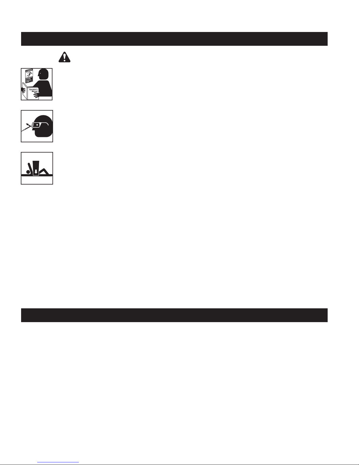
•Study, understand, and follow all instructions before using this device. If the operator
cannot read these instructions, operating instructions and safety precautions must be
read and discussed in the operator’s native language.
•Before using the service jack to lift a vehicle, refer to the vehicle service manual to
determine recommended lifting surfaces on the vehicle chassis.
•Wear eye protection that meets ANSI Z87.1 and OSHA standards.
•Inspect the jack before each use; do not use the jack if it’s damaged, altered, or in poor
condition. Take corrective action if any of the following conditions are found: cracked or
damaged housing; excessive wear, bending, or other damage; leaking hydraulic uid;
scored or damaged piston rod; loose hardware; modied or altered equipment.
•A load must never exceed the rated lifting capacity of the jack.
•Use the jack on a hard, level surface. The jack must be free to roll without any obstructions
while lifting or lowering the vehicle. The wheels of the vehicle must be in the straight-
ahead position, and the hand brake released.
•Use the jack for lifting purposes only. Stay clear of a lifted load. Place support stands under the
axles before working on the vehicle.
•Center the load on the jack saddle. Off-center loads can damage seals and cause jack failure. Lift
only dead weight.
•Do not use blocks or other extenders between the saddle and the load being lifted.
•Do not modify the jack or use adapters unless approved or supplied by OTC.
•Lower the jack slowly and carefully while watching the position of the jack saddle.
• Use only approved hydraulic uid (Chevron AW Hydraulic Oil or equivalent). The use of alcohol,
hydraulic brake uid, or transmission oil could damage seals and result in jack failure.
This guide cannot cover every situation, so always do the job with safety rst.
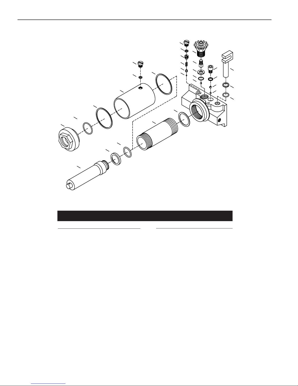
Parts List & Operating Instructions Form No. 522982, sheet 2 of 3, back
Setup
Assembling the Handle
1. Loosen the thumb screw on the back of the handle socket.
2. Grease the socket opening. Insert the handle.
3. Torque the thumb screw again to 150–200 in. lbs.
Bleeding Air from the Service Jack
Air can accumulate within a hydraulic system during shipment or after prolonged use. This entrapped air
causes the jack to respond slowly or feel “spongy.” To remove the air:
1. Open the release valve by turning the handle all the way counterclockwise (CCW).
2. Pump the handle six full strokes.
3. Close the release valve by turning the handle all the way clockwise (CW).
4. Pump the handle until the lift arm is fully extended.
5. Lower the lift arm by turning the handle all the way counterclockwise (CCW). If the jack does not
immediately respond, repeat steps 2–4.

Sheet No.
Issue Date: Rev. C March 19, 2012
© 2003 SPX
Operating Instructions
1. Close the release valve by turning the handle clockwise (CW) as far as it will go.
2. Position the jack under the vehicle. IMPORTANT: Use the manufacturer’s recommended lifting points
on the chassis.
3. Pump the jack handle to raise the saddle to the contact point.
4. Check the placement of the jack; the load must be centered on the jack saddle. IMPORTANT: Avoid wheel
obstructions such as gravel, tools, or uneven expansion joints.
5. Finish lifting the vehicle by pumping the handle. Do not attempt to raise the jack beyond its travel stops.
6. Place approved support stands under the vehicle at points that will provide stable support. Before making
repairs on the vehicle, lower it onto the support stands by SLOWLY and CAREFULLY turning the handle
counterclockwise (CCW).
Parts List & Operating Instructions Form No. 522982
Preventive Maintenance
IMPORTANT: The greatest single cause of failure in hydraulic units is dirt. Keep the service jack clean
and well lubricated to prevent foreign matter from entering the system. If the jack has been exposed to rain,
snow, sand, or grit, it must be cleaned before it is used.
1. Store the jack in a well-protected area where it will not be exposed to corrosive vapors, abrasive dust, or
any other harmful elements.
2. Regularly lubricate the moving parts in the wheels, arm, and handle.
3. Replace the oil in the reservoir at least once per year. To check the oil level, lower the lift arm completely.
Remove the rubber ller plug. Oil level should be at the bottom of the ller plug hole. If necessary, add
approved anti-wear hydraulic jack oil, and install the ller plug. IMPORTANT: The use of alcohol, hydraulic
brake uid, or transmission oil could damage the seals and result in jack failure.
4. Inspect the jack before each use. Take corrective action if any of the following problems are found:
a. cracked, damaged housing c. leaking hydraulic uid e. loose hardware
b. excessive wear, bending, other damage d. scored, damaged piston rod f. modied
equipment
5. Keep warning labels and instructional decals clean and readable. Use a mild soap solution to wash external
surfaces of the jack.
3 of 3

Jack does not lift
Jack lifts only partially
Jack advances slowly
Jack lifts load, but doesn't hold
Jack leaks oil
Jack will not retract
Jack retracts slowly
1. Release valve is open.
2. Low/no oil in reservoir.
3. Air-locked system.
4. Load is above capacity of jack.
5. Delivery valve and/or bypass valve not
working correctly.
6. Packing worn out or defective.
1. Close release valve.
2. Fill with oil and bleed system.
3. Bleed system.
4. Use correct equipment.
5. Clean to remove dirt or foreign matter.
Replace oil.
6. Replace hydraulic unit.
1. Too much or not enough oil. 1. Check oil level.
1. Pump not working correctly.
2. Leaking seals.
1. Replace hydraulic unit.
2. Replace hydraulic unit.
1. Cylinder packing is leaking.
2. Valve not working correctly (suction,
delivery, release, or bypass).
3. Air-locked system.
1. Replace hydraulic unit.
2. Inspect valves. Clean and repair seat
surfaces.
3. Bleed system.
1. Worn or damaged seals. 1. Replace hydraulic unit.
1. Release valve is closed. 1. Open release valve all the way
counterclockwise (CCW). May be
necessary to clean release valve.
1. Cylinder damaged internally.
2. Link section is binding.
1. Send jack to OTC-authorized service
center. (Refer to OTC Form No. 104060.)
2. Lubricate or replace link section.
Parts List & Operating Instructions Form No. 522982, sheet 3 of 3, back
Troubleshooting Guide
Repair procedures must be performed in a dirt-free environment by qualied personnel who are familiar with
this equipment. CAUTION: All inspection, maintenance, and repair procedures must be performed when the jack
is free of a load (not in use).
Trouble Cause Solution
This manual suits for next models
1
Table of contents
Other OTC Jack manuals