OTOLIFT 87 User manual

Otolift type 87
Installation manual
Date 221209

1
Installation Manual
TYPE 87
Table of content page
1. Chair lift assembly 3
2.Railassembly 5
2.1 Assembling the rail 5
2.2 Charge-points 7
2.3 Installing the chair on the rail and testrun 8
2.4 Finishing the rail 10
3. Remote control assembly 11
4. Transmitters and receivers 12
4.1 Teaching the 2-channel remotes into a 2-channel receiver 12
4.2 Reverse logic up/down of 2-channel receiver. 12
4.3 Adjusting the dipswitches of the 1-channel transmitter and receiver 13
4.4 Types and type numbers 13
5. Programming the chairlift 14
5.1 Need to know before programming 14
5.2 Programming the chairlift 15
6. Completing the lift in case of a sliding rail 16
7. Completing the chair 17
8. Testing the chairlift 18
8.1 Sensitive edges 18
8.2 Safety switches/inputs 19
9 Locating and correcting malfunctions 20
9.1 Diagnostic display. 20
9.2 LED’s on the PCB 21
9.3 8888x error 21
9.4Reset 21
9.5 Fuse safety-line 22
9.6 Bypass-connector 22
9.7 Interconnections on the PCB 22
9.8 Transformer/ on board charging-circuit 23
9.9 Dipswitches 23

2
1. Chair lift assembly
Before you start assembling the rail it is recommended to assemble the chair first at the upper end of
the stairscase. (end location of lift) .
1. Take carriage, seatframe , seat and back-seat to the upper end of the staircase.
2. Unscrew the coverplate of the rotating disc, and take the bearing set of.
3. Put the needle bearing between the
2 rings on the rotating disc.
4. Place the seatframe on the
bearingset and place on top
the other needle bearing set.
5. Now the coverplate can be mounted
on top of the above-mentioned disc
and fastened with the socket screws.
Make sure that all bearings are
aligned properly
5. Check if the swivel seat is functioning properly and turn the bolts tightly.
Rotating disc
And bearing set
Coverplate
fastened
Seat with bearing
set and
coverplate

3
6. Put the cables through the rotating
disc.
Start with the 5 pole connector
(armrest)
Then the 3 pole, then the 2 pole
connector.
7. Guide the cables through the carriage to the PCB.
(Check if the mechanism of the footrest can not damage the wiring.)
8. Attach the cabling to the seatframe and connect the black wire to the seat frame by a m4 bold
(Check if the bolds of the rotating disc can not damage the wiring.)
9. Connect the wiring to the main PCB
(3 pole to X2a, 5 pole to x2b and the 2 pole to x2c)
10. Assemble the seat by using the 4 m6 x 16mm bolt and the 3 countersunk m6 x 16 bolt.
11. Mount the back of the back-seat by pushing the holes over the metal buttons and then slide it
downwards.
Both cables
connected
to PCB
Cables through
carriage
Cables attached to seat frame.
Black connected to frame
Bolts at the back
of the seat Back of back-
seat mounted
Bolts at the back
of the back-seat
Bolts at the front
side of the seat
1 2

4
2. Rail assembly
2.1 assembling the rail
Below you see a drawing of a rail with a sliding hinge.
The drawing shows the type of legs, the total length of the legs and the different angles of inclination.
BP xxx stands for bottom leg.
RP xxx stands for straight leg.
The xxx number named after the BP or RP is the length of the leg in mm

5
The length of the leg and all the other mentioned lengths of legs should be adjusted before you place
the lift on the staircase. The mentioned length is the length from the bottom of the BP till the top of the
5mm plate which is welded at the strip of the rail.
With screw A you tighten the leg at the strip if the rail.
The screw should be clamped to the small side of the strip.
When you adjust the length of the leg you only tighten screw C first.
The bottom leg. (at ground floor) should not/ and cannot be adjusted.
Also when you have a horizontal parts at the top no adjustment in height is possible.
Steps to be taken
1. Assemble the legs to the rail parts.
2. Adjust the length of the legs
3. Put the lowest rail part on the staircase.
4. In case you have a lift with a powered sliding rail, you should now connect the 9V recharge-
able batteries to the hinge PCB. (inside the box of the mechanics of the sliding rail).
5. Put the second rail part on the staircase.
6. Connect the wiring of the two parts together. (Red to Red => Black to Black => Grey to Grey)
7. Isolate this wiring by taping them to prevent internally interconnections or interconnections to
the inside of the rail.
8 No couple the rail part together. (possible you need to unscrew some already attached screws
first.)
Water-leveler
and adjusting
the length
Coupling
of wiring

6
11. If you have more railparts repeat step 5 to 10.
12. At this moment the complete rail should stand on the staircase.
On the drawing of the rail you see different angles of inclination mentioned.
Check the inclination by using a adjustable water-leveler.
Start at the bottom and work your way up.
When doing this you can or have adjust the lengths of the legs.
Probably you need to compromise a little at angles of inclination.
Check if the bottom leg is standing (or keeps standing) on the ground floor.
It is important that a sliding/folding railpart always has a angle of 56 degrees.
Try to keep the angles of inclination as accurate as possible.
Most important are the places where the user steps on or off the chairlift. (bottom and top)
13. If the complete rail has the correct angle of inclination, the rail can be positioned at the correct
spacing to the wall. Dimensions for this spacing are given in the drawing.
NOTE During moving the rail on its final position, keep in mind that in case of a sliding or
folding rail you should keep some spacing around the leg or its ground-plate.
When this bottom leg has some tension, it is possible that the hinge will not work properly
(gives to much friction).
14. Connect charging-points and transformer (described in chapter 2.2)
NOTE In case of a folding rail the transformer should be connected to the rail PCB.
15. When the charging-points and transformer are connected it is time to install the chairlift on
the rail. (see chapter 2.3)
In case of a straight rail we advise you to fasten some legs to the staircase first.
. (to prevent instability of the rail)
Spacing measured
between front-side
of the rail till the
wall or ob
j
ect.
9. Clamp a piece of rack to get a good pitch of the toothed-rack.
10 Tighten all screws of all coupling parts.

7
2.2 charge points
•Connect the transformer to the charge point of the rail as shown in the drawing.
•Connect the transformer to the wall socket (mains voltage 230Vac)
Powered hinge (folding)
1
2
3
1
2
1=red (voltage for charging)
2=black (0V)
1=brown (voltage for charging)
2=blue (0V)
1
2
1
2
3
1=red (voltage for charging)
2=black (0V)
3=grey (24V output)
1
3
Connector J6
(PCB ssp 042 v6)
2
Powered hinge (sliding)
Standard
47mm
25mm
6.5mm
Connector A/B
(ssp 007 V3)
1=red (voltage for charging)
2=black (0V)
3=grey (24V output)
1=red (charging-voltage indirect)
2=black (0V)
3=grey (24V output swithing)
2
1=red (chargingvoltage indirect)
2=black (0V)
3=grey (24V output swithing)
Transformer
24Vdc output
Fuse =1,6AT
brown blue
blue
brown
Transformer
24Vdc output
Fuse =1,6At
1=red (voltage for charging)
2=black (0V)
2
2
31
2
Transformer
24Vdc output
Fuse =1,6AT
brown blue
1=brown (voltage for charging)
2=blue (0V)
NOTE. In case of a folding rail the
transformer should always be connected
to the rail PCB SSP007v3.
NEVER directly to the chargepoints

8
2.3 Installing the chair on the rail.
Introduction
Mounting the chairlift on the rail and testrunning the chairlift can be done by using the servicebox.
The chair has to be completed first and the transformer has to be connected to the mains.
Connect the batteries of the chair.
The red wire has to be connected to the +BATT+ and the black wire to the –BATT-.
The connector of the service box should be connected to X13 (service) (main PCB on the left)
When you switch on S (service) upwards you should be able to drive the lift left or right by controlling
L or R. By changing the position of the potentiometer the actual speed can be adjusted.
When every switch/contact is correctly connected and in the right position, the
display should show 1.
If not, the lift probably can not drive in one or both directions.
Check chapter 9 for the display logic en LED logic to find the cause of the problem.
NOTE. When a sensor is applied the display will keep showing error 3.
This because the sensor ‘sees’ no metal.
The sensor (proximity switch) is mounted in metal block of the counter
pressure rol.
To activate the sensor, keep a metal tool against the sensor. See picture.
The sensor monitors the distance to the lower tube.
When the chairlift is on the rail the sensor should be activate continuously,
when the distance to the lower tube and sensor is less then 4mm.
Servicebox control
S= Service => switch upwards = on
T = Teach in => switch upwards = on
L = move Left
R= move Right
1 2 = speed 1or 2
C= Hold to run Connector Bypass (see 9.6)
Service-
connector
Dipswitches
Display
Sensor

9
Installing the chairlift on the rail
1. Check if lift is functioning OK.
2. Remove the end plate and the buffer from the top of the rail
See figure.
3. Place the chair on the rail. Check during putting the lift on the
rail that the overspeed governor does not grip the rail and in
case of a lift with sensor, that you do not damage the sensor.
Before step 4, make sure that the drive unit is on the rail
correctly, the counter pressure roll is around the bottom tube
of the rail and that the toothed wheel against the toothed rack.
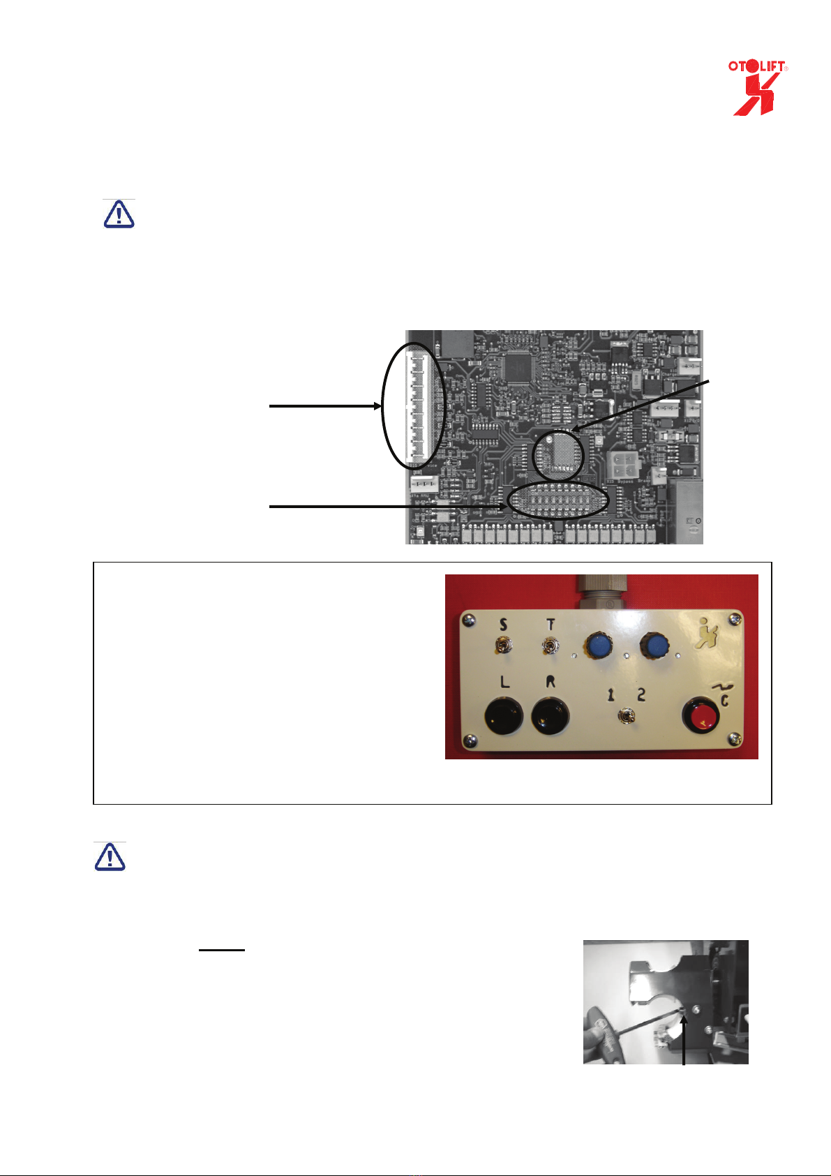
4. Connect the service box to the main PCB of the chair.
Make sure that all the switches on the service box are switched off (pointing downwards)
5. Switch on the manual operation, by switching “Service” on the service box upwards.
6. Set the speed of the motor to a low level by adjusting of the potentiometer on the service box.
(counter clock-wise= low speed)
7. Drive the chair slowly on to the tooth rack by operating the switches “left” or “right” on the
service box.
8. Assemble the endplate and the buffer at the top of the rail. Move the lift a little downwards to
remove the transport standard.
9. Check if the safety switches on the gearwheel covers are functioning properly by operating the
switches during movement.
Testrun
1. Drive the chair completely to the bottom of the stairs to check the proper running, by using the
service box.
(in case of a sensor keep monitoring the distance between sensor and lower tube)
Do not forget to remove the clamp and the piece of toothrack, which was used for coupling the
railparts and watch out for clearances between lift and other objects.
2. The chair has to stop, when the gearwheel cover (safety-cap endswitch) runs into the buffer.
During the test-run you monitor the spacing between chairlift and the staircase or other object
which can obstruct the way of stairlift.
3. Also check the spacing to objects or staircase, with the footplate in fold out position and
armrest in upwards position.
Check correct function
of endswitch
Buffer and
endplate mounted
Placing the chair
on the rail
(
model 2002
)

10
2.4 finishing the rail
At this moment the testrun is finished and the rail is standing on its final position.
In case of hinged rail, the leg still has to have 0,5~1 cm space between the bottom leg
and staircase.
If you have a hinged rail, wait with fastening the bottom leg..
1. Fasten the legs with the screws and plugs supplied by Otto Ooms BV.
Screw 6.3 x ..mm Plug 8mm
length
Whitewood Screw must enter the wood for a minimum of 30 mm (recommended screw 6.3 x 38 mm)
Hardwood Screw must enter the wood for a minimum of 20mm. (recommended screw 6.3 x 32 mm)
Concrete Use the 8mm plugs and the screws6.3 x 50mm
The upper mentioned screw lengths are based on good structure and quality of
staircase and floor.
The screws used assembling the legs and groundplates should be able to hold a
minimum tensile of 350 N.
When a soft carpet is on the staircase it is recommended to untighten screw C of the leg first,
to prevent to pull the lift more downwards into the carpet.
When the leg is fastened tighten screw B and C on the legs.
When the lift has a horizontal part, you can adjust the rail (waterlevel) a little by un-tighten and
tighten the bolds on the side of the groundplate.(4pcs)
In case of a hinged rail we recommend to test the hinge, before fastening it.
The best time to do this, is when the remotes are assembled and the lift is
programmed in.
2. When all screws and bolds are tightened you can put the plastic caps over the leg.
You do this by breaking the cap at the flat side, fold them over the bottom leg (BP), and lock
them by using the plastic piece inside.

11
3. Remote Control assembly
•First of all an appropriate place has to be selected to install the remote control unit. From the
position where the unit is located, one must have a good overview of the major part of the
chair lift.
•Fit the base plate to a flat wall and clamp the PCB on the base plate.
•Attach the protection cap, holding the buttons, with the screws to the base plate. (4 pcs)
•Place the battery in the holder on the board. Pay attention to the correct +/- polarity.
Only use alkaline batteries: AA LR6 1,5 V.
•Click the cover over the base plate.
•Check the free functioning of the buttons.
In case the chair lift is provided with a sliding rail, you have to install an additional transmitter
below the remote control.
It is needed to control folding and unfolding the sliding rail.
Base plate Cap mounted
Standard or folding
hinge
Sliding hingeBattery connected
PCB mounted

12
4. Transmitters and receivers
The chairlift has a separated receiver (PCB) built in for remote-control.
In case of a powered sliding hinge 2 extra remotes and 1 receiver is used for controlling the hinge in
and out.
Also an extra 1-channel transmitter (on the hinge) and 1-channel receiver (in the chairlift) is applied for
hinge-is-down command.
Before using the remote you have to teach them in and/or adjust the dipswitches.
The battery-voltages has to be connected, when you want to teach them in.
4.1 Teaching the 2-channel remotes into a 2-channel receiver
1. Open the cover of the receiver-box.
2. Operate the switch on the receiver once. (LED lights up).
3. Operate within 30 seconds the up or down switch of the remote which should be programmed
in. The LED will go off.
(Battery on remote should be connected.)
4. The up and down signal of the remote now will be ‘seen’ by the receiver.
5. Repeat step 2 and 3 for the next remote.
(programming up to 16 remotes is possible.)
2-channel receiver 2-channel remote
•For deleting the transmitters, keep switch on the receiver operated, until the LED dims. (5
seconds)
•With the dipswitches, the send- and receive frequency can be changed.
•The dipswitches on the remotes and the receiver have to be adjusted in the same position.
(always both on or both off)
4.2 Reverse logic up/down of the 2 channel receiver.
Depending on whether a rail is mounted at the left or right side of a staircase the logic (up/down) of the
remote might have to be reversed.
When dipswitch 9 = on, the remote-control is adjusted for right rail.
When dipswitch 9 = off, the remote-control is adjusted for left rail. (standard)
Dipswitches
LED
Switch
Switch
up/down

13
4.3 Adjusting the dipswitches of the 1-channel transmitter and receiver
To make the 1-channel receiver work with the 1-channel transmitter you have to adjust the
dipswitches of both in the same way.
1-channel receiver 1-channel transmitter
The receiver and transmitter always have the same dipswitch settings, when they come from the
manufacturer.
We recommend to adjust the dipswitch always to prevent that a signal from another hinge can give a
false hinge-is-down command.
4.4 Types and type numbers
2-channel remote = SKE2MLV
2-channel receiver = EKE2MLV
1-channel transmitter = SFB1LV
1-channel receiver = EFB1LV
Dipswitches

14
5. Programming the chairlift
5.1 Need to know before programming
The chairlift must always be programmed, when moving to the right. (seen from user position)
Thus a lift which is mounted on the left side of the stairs, must be programmed from the endpoint at
the top till the endpoint of the bottom, and a lift which is mounted on the right side of the stairs, must
be programmed from endpoint of the bottom till the endpoint at the top.
Be careful, when using the servicebox in bypassmode the lift only stops when an endswitch is
operated. (Bypass see chapter 9.6)
When an overspeed governor is mounted on the chairlift, and the bypass-connector is connected and
activated, the lift will not stop when the overspeed governor contact (catch) opens.
Please keep this in mind.
Servicebox control
S= Service => switch upwards = on / down = off
T = Teach in => switch upwards = on / down = off
L = move Left => switch operated = on
R= move Right => switch operated = on
1 2 = speed 1or 2
C = Hold to Run Button Bypass Connector
Before programming, always check to make sure the lift stops at the endswitches.
Service + Left: the lift must stop when safety-cap endswitch left is controlled.
Service + Right: the lift must stop when safety-cap endswitch right is controlled.
The speeds must be set before starting programming the lift.
The position of the potentiometer is related to the speed.
With the switch below the potentiometers (1 2) you can choose the potentiometer-speed .
To see the actual set (potentiometer) speed, move the lift by Service and Left or Right.
During movement in service mode you can adjust the speeds.
Do not adjust the potentiometers during programming procedure.

15
5.2 Programming the chairlift
Start programming procedure when ‘potentiometer’ speed is set.
Programming procedure:
1 Switch on Service.
2 Move the chairlift to the left by operating Left (servicebox), until it stopped against the buffer
3 Release Left
4 Switch off Service.
5 Choose speed 1 or 2 (switch 1 2) speed should be set before programming procedure
6 Switch on Teach
7 Operate Right (on servicebox) (the chairlift begins to move).
Keep Right operated till point 10.
8 If necessary, switch over the speed by operating switch 1 2.
(Max of 35 times of switch over in speed possible)
9 If the chairlift has stopped against the other buffer, the system beeps 5 times.
10 Release Right
11 Switch off Teach
12 Remove the connector from the service box if there are no additional charging points.
If an extra charge point has been installed on the rail, the chair can be programmed in for this.
Programming procedure for extra charge-point(s)
13 Switch on Service
14 Move the chairlift to the extra charging point.
15 Park the chairlift exactly in the middle of the charging point.
16 Leave the system on Service and switch on Teach mode, the system will beep once.
17 Switch off Teach.
18 Switch off Service.
19 Remove the plug from the service box.
If a second extra charging point has been installed, this can be programmed into the chairlift as well.
Repeat points 13 through 19, the system will beep twice at point 16. (3th charging-point 3 times...etc.)
In total 5 extra charging points/stoppoints can be added.
Extra charging-points can not be deleted.
When a incorrect charging-point has been programmed in, start at point 1.
You can choose for which control the chairlift should stop on the extra charging point(s)
Dipswitch 4 = on, the lift will stop when operated on by the remote-control.
Dipswitch 5 = on, the lift will stop when operated on the armrest.
Dipswitch 4 + 5 = on, the lift will stop when operated by the remote-control as well as on the armrest.
Activate alarm when controlled by remote
Alarm during movement when controlled by remote can activated or de-activated by controlling L+R
1sec on the servicebox. (Service and/ or Teach should be in off position)
This functionality is added in software version C40 or higher.
Only start programming the lift, when the lift is operating OK (without bypass-connector.)
The hinge should stand in the hinge out position.
Keep the transformer connected to the mains-voltage

16
6. Completing the lift in case of a hinge rail
In chapter 2.5 we recommended to wait to fasten the bottom leg in case of a hinged rail.
This because it is easier to do when remotes are mounted and function and the chairlift is
programmed in.
Now drive the lift to a chargepoint and test the functionality of the hinge.
The folding hinged rail should fold in automatically when it the chairlift is not controlled by remote or
armrest for 4 seconds.
When you control the lift it folds out. (only when swivelseat-switch is in correct position and
armrestswitch is on position. (upwards).
The sliding rail must be controlled by the remote-control which is mounted under the control of the
chairlift.
If the hinge not functioning properly, move the leg a little to make it work.
In 99% this is the cause of a bad functionality
If the powered hinge works OK, first tighten one screw, then check the functionality again.
If it is still functioning properly then tighten the next screws.
Adjusting the mechanics of the sliding rail
•Adjust the sliding rail by using the M6 bolt on the hinge. If the M6 bolt is tightened, the end of
the sliding rail will move upwards, so that the clearance on the aluminum locking hooks of the
sliding rail can be reduced. (A minimum of clearance should be kept.)
Test the functionality during adjusting,
(The adjustment also changes the location of the rotationpoint at the bottom of the rail.)
Fasten with the lock nut.
•Adjust the force that opens and closes the sliding rail by tightening or loosing the slip-coupling
on the sliding rail motor.
(keep in mind that the slip-coupling looses some torch during the first weeks)
•Lock the coupling with the locking ring.
Folding rail
•The folding rail must work without any frictional resistance.
When there is too much frictional resistance in the mechanics, the folding rail- P.C.B. stops
controlling its motor. (thermal protection)
•As lubricant inside the application, use TEFLON OIL.
On the lock plate only use optimal white paste.
Clearance
locking hooks Slip-coupling
Adjusting
m6 bolt
Lock-plate

17
7. Completing the chairlift
Before starting completing the chair check if the hinge switches the lift off, when it is fold in.
In this case the display shows 3. ( when fold in not or not completly fold out position)
•Fit the chairlift with the side caps by hanging the side caps in the holes at the top of the frame,
and next sliding the side caps to the back of the chair.
•Place the springs over the switch. (left and right side)
•To assemble the bottom cap to the chair the two holes at the back of the cap have to be
placed over the two synthetic rings at the back of the chair. Hook the bottom cap into the side
caps and place the front of the bottom cap over the synthetic ring at the front of the chair.
•Next the front plate must be put in place. Hook the front plate in the holes at the top of the
chair and fasten the plate with bolts at the bottom. (2,5 mm hexagon socket wrench)
•Fit the operation handles of the footrest by pushing them over the pipes and fasten the
handles with bolts in the pipe. (2,5 mm hexagon socket wrench)
Front-plate
hooked in the top
Fasten
frontplate
Side caps frame
Fasten handles
footrest
1 1
2
Synthetic rings
at the back
Bottom-cap hooked
in side-cap
Bottom-cap hooked
In side-cap (mounted)
Bottom-cap hooke
on ring at the front.

18
8. Testing the chair
8.1 sensitive edges.
The chair has to stop if it runs into an obstacle by the footrest , the side of frame, the bottom of the
frame, the drive unit and the safety cap of the endswitch.
The safety mechanisms are located at both sides of the chair and work independently from each
other, so that if, for example, the side cap on the left side of the chair runs into an obstacle, the chair
can still be moved to the right.
If the bottom of the chair runs into a obstruction the chair can still be moved upwards.
•Make sure all the safety mechanisms are working properly in both directions.
•When the lift stops the system gives a number of beeps when stopped. (when control is released)
The number of beeps gives the location of the controlled sensitive edge.
The location of the controlled sensitive edge is at the same side as the controlled direction.
•When 2beeps are heard the safety cap of the drive-unit is controlled.
•When 3beeps are heard the safety-plate of the footplate is controlled.
•When 4beeps are heard the safety-cap of the chairframe is controlled.
(also check bottom of chairframe)
•When 5beeps are heard the safety-cap of the endswitch is controlled.
(The 5 beeps are given in the current software only when the chair is positioned on a endpoint,
in the upcoming software on every loctation.)
Safety footrest
Safety bottom of
frame
Safety drive unitSafety endswitch
Safety side of
frame.

19
8.2 safety switches/inputs
On the lift itself switches are build in to prevent driving in both directions.
One is positioned in the armrest (chair on/off).
The other switch is in the swivel seat, to prevent that movement of the lift is impossible, when the
rotating seat is not in the correct or locked position.
On/off switch in armrest Unlocking swivel seat
In case of a sliding rail or sensor the lift will switched off when the sliding hinge is not in the correct
position or when the sensor ‘sees’ no metal.
You can check the working of the sensor by pushing the chairlift a little backwards.
When one of the above named switches or inputs is not activated (not in on position) the LED in
armrest will be off.
By operating (1 sec.) and releasing the control left/right on the armrest we LED wil show a number of
blinks. The number of blinks refer to a specified (group of) switch(es) or inputs.
•The Led blinks 0times. The keyswitch in the armrest is switched off.
(keyswitch is an option)
•The Led blinks 1time The armrest-switch is switched off.
(Note On is switch in highest position)
•The Led blinks 2times The switch of the swivel seat is still
operated. Check the position of the seat and
locking handles.
•The Led blinks 3times The chair is switched off because the powered
hinge is not in the correct position or that the sensor
‘sees’ no metal.
Other manuals for 87
1
Table of contents
Other OTOLIFT Stairlift manuals