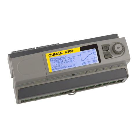
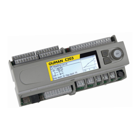
OUMAN C203 User manual

www.ouman.fi
www.ouman.fi
XM1397: Version 1.5.3->
Regulator for the
three circuits
- control for 2 heating circuits
- 1 domestic hot water control
USER
MANUAL
C203
Menu główne
Pomiary
O1 Woda zasilająca
O2 Woda zasilająca
C.W.U. Sterowanie

2
This user manual explains the C203 regulator’s functions and the displays that are visible to all users. The
service mode functions are covered in separate service manual at www.ouman.fi.
The regulator also has a service mode that is used when connecting and implementing features as well as
the regulator’s configuration. It includes certain setting values that do not usually need to be changed or
require in-depth knowledge of the regulation process.
The C203 is a heat regulator for 3 circuits (two heating circuits and one hot water circuit). Wiring and con-
figurating selections define what the regulator displays on the display screen.
Turn the control knob
to navigate in the menu.
A maximum of five windows can be displayed with the favourite
views key. Default settings for favourite views show menus for
each circuit, including all default settings that can be changed
by the user as well as information about measurements and the
regulator’s operation.
You can move from one favourite view to another by tapping
the key.
Press the control button to en-
ter the menu.
Control knob and OK
Cancel button
Basic view
Holding the key down for an exten-
ded period of time returns the regu-
lator to its basic mode. The display
shows the basic view, the monitor
dims and the keyboard locks if the
locking function is in use.
Pomiary
O1 Układ sterowania
O2 Układ sterowania
C.W.U. Sterowanie
Menu główne
>
>
>
>
OK
OK
Temp. zewnętrzna
O1 Woda zasilająca
O2 Woda zasilająca
C.W.U. Woda zasilająca
Automatyczny
Automatyczny
Automatyczny
19.4°C
19.2°C
19.8°C
58.0°C
13:51 29.07.2018 2
Wybór

3
1 Display menus 4
1.1 Basic view 4
1.2 Favourite views 5
1.3 Menu structure 6
2 Measurements (Pomiary) 7
2.1 Obraz trendu 7
3 Regulation of supply water in heating circuits 8
3.1 Supply water information (Woda na zasilaniu – informacje) 8
3.2 Room temperature information (Informacja o temp.pokojowej) 9
3.3 Measurements (Pomiary) 9
3.4 Heating curve (Krzywa grzewcza) 10
3.5 Setting values (Ustawienie wartości) 11
3.5.1 Room temperature settings (Ustawienie temp. pokojowej) 11
3.5.2 Temperature drops (Spadki temperatur) 12
3.5.3 Special setting values (Ustawienia zaawansowane) 12
3.6 Control mode (Tryb sterowania) 15
3.7 Time programs (Programy czasowe) 16
3.7.1 Weekly schedule (Spadek temp. Harmonogram tygodniowy) 16
3.7.2 Exception schedule (Harmonogram wyjątków) 17
3.7.3 Special days (Dni specjalne) 17
3.6.4 Temp. level according to time program (Poziom temperatury wg.programu czasowego) 17
4 Domestic hot water control (C.W.U. Sterowanie) 18
4.1 Setting values (Ustawienie wartości) 18
4.2 Tryb sterowania 18
4.3 Pomiary 18
4.4 Time programs (Programy czasowe) 19
4.4.1 Weekly schedule (Harmonogram tygodniowy) 19
4.4.2 Exception schedule (Harmonogram wyjątków) 20
4.4.3 Special days (Dni specjalne) 20
4.4.4 Temperature increase/drop Present value (C.W.U. Wzrost/Spadek. Aktualna wartość) 20
5 Alarms (Alarmy) 21
5.1 Active alarms (Aktywne alarmy) 22
5.2 Alarm history (Historia alarmów) 22
5.3 Acknowledge all alarms (Potwierdź wszystkie alarmy) 22
5.4 Reset alarm history (Usuń historię alarmów) 22
5.5 Alarms receivers (Odbiorcy alarmów) 22
5.6 Routing schedule (Harmonogram tygodniowy) 23
6 System settings (Ustawienia systemowe) 24
6.1 Setting date, time and language (Czas, Data, Wybór języka) 24
6.2 Text message (SMS) settings (Ustawienia SMS) 24
6.3 Network settings (Ustawienia sieci) 25
6.4 Display settings (Ustawienia wyświetlania) 29
6.5 Type info (Rodzaj informacji) 29
6.6 Lock code (Kod blokady) 29
7 Communication via a mobile phone 30
Other remote control options 30
Optional equipments and remote control options 31
Connecting the modem and taking it into use 31
Technical information 32
Index

4
Central factors related to controlling heating are visible in the regulator’s basic view. When the unit is dor-
mant (keys have not been touched) the display shows the basic view.
Dierent levels of display menus are used to make the C203 clear and easy to use. The basic view shows the
most important information for monitoring operation of the unit. Favourite views that can be changed by
users enable them to easily access desired menus. Setting values needed by the user can easily be found in
the versatile menu structure.
1 Display menus
• A blinking exclamation
point means the unit
has active alarms.
• The number indicates
the number of alarms.
Temperature measurements
enable quickly determining pro-
per operation of the circuit.
Circuit control. This shows whether the
circuit’s heating level has been conti-
nuously forced to a particularly level or if
the regulator is in manual mode.
Alarms
Temp. zewnętrzna
O1 Woda zasilająca
O2 Woda zasilająca
C.W.U. Woda zasilająca
Automatyczny
Automatyczny
Automatyczny
19.4°C
19.2°C
19.8°C
58.0°C
13:51 29.07.2018 2
Wybór
1.1 Basic view
C203 can generate dierent kinds of alarms. In the event of an alarm,
an alarm window pops up showing detailed alarm information and a
beeping alarm signal goes o.
If there are several unacknowledged alarms and you acknowledge
the alarm currently appearing in the device display, the previous alarm
will appear. As soon as all active alarms have been acknowledged, the
alarm window disappears and the alarm signal stops.
Alarm signal of all active alarms may also be stopped by pressing Esc
button. When you press Esc, the alarm signal stops and all the alarm
windows disappear from the display.
You may look into the alarms later by going to ”Alarms” > ”Active alarms”.
If an alarm has been acknowledged by pressing Esc, an exclamation
mark will appear in the beginning of the row.
Alarm notice
Acknowledging alarms: Press OK and
the alarm sound will stop. If the reason
for the alarm has not been corrected, the
exclamation point in the top right will
continue to blink.
O1 Alarm przegrzania
PR 1 GRUPA 1
O1 Woda zasilająca =10.2 °C
Odebrane: 08.11.2018 02:27
Naciśnij OK, aby potwierdzić alarm

5
Temp. zewnętrzna
O1 Woda zasilająca
O2 Woda zasilająca
C.W.U. Woda zasilająca
Automatyczny
Automatyczny
Automatyczny
19.4°C
19.2°C
19.8°C
58.0°C
13:51 29.07.2018 2
Wybór
You can easily navigate from the basic view to the desired menu using the favourite view function. You can
navigate from one favourite view to another by tapping the button. There can be a maximum of five of these
views. The pre-installed favourite views show the circuits’ main menus. You can also save a particular regu-
lator view as your own favourite view. You can return from favourite views to the basic view by tapping the
ESC key until the basic view appears.
Navigate to the view you want to add to your favourite views. Hold down the key for an extended period
of time until the ”Save view in memory location:” menu opens. Use the dial to select the position where you
want to add the favourite view and press OK. If you select a location where a favourite view has already
been saved, the new favourite view will replace the existing one.
Basic view
H2 Circuit menu
H1 Circuit menu
DHW Circuit menu
Setting a favourite view
Your own favourite view
1.2 Favourite views
O1 Układ sterowania
O2 Układ sterowania
Woda na zasilaniu – informacje
Informacja o temperaturze pokojowej
Pomiary
O1 Krzywa grzewcza
Woda na zasilaniu – informacje
Informacja o temperaturze pokojowej
Pomiary
O2 Krzywa grzewcza
>
>
>
>
>
>
>
>
C.W.U. Sterowanie
Ustawienie wartości
Tryb sterowania Automatyczny
Pomiary
Programy czasowe
>
>
>
>
Historia alarmów
02.12.2016 10:11:42 Błąd czujnika O1: Woda z
05.12.2016 11:22:40 Błąd czujnika O1: Woda po
>
>
2

6
The service mode is covered in the
C203 Service manual (Installation and con-
figuration).
Menu główne Page 7
In the user manual
Page 8
Page 8
Page 18
Page 21
Page 24
Pomiary
O1 Układ sterowania
O2 Układ sterowania
C.W.U. Sterowanie
Alarmy
Ustawienia systemowe
Serwis
>
>
>
>
>
>
>
Pomiary
Temp. zewnętrzna -18.2 °C
----------------------------------------------------
O1 Woda zasilająca 35.1 °C
O1 Powrót wody 22.0 °C
O1 Temperatura pokojowa 21.5 °C
O1 Sterowanie siłownikiem 22 %
----------------------------------------------------
O2 Woda zasilająca 28.1 °C
O2 Powrót wody 21.1 °C
>
>
>
>
O1 Układ sterowania
O2 Układ sterowania
Woda zasilająca
Informacja o temperaturze pokojowej
Pomiary
O1 Krzywa grzewcza
Ustawienie wartości
Tryb sterowania
Programy czasowe
Woda zasilająca
Informacja o temperaturze pokojowej
Pomiary
O2 Krzywa grzewcza
Ustawienie wartości
Tryb sterowania
Programy czasowe
>
>
>
>
>
Automatyczny
>
>
>
>
>
>
>
Automatyczny
>
>
1.3 Menu structure
C.W.U. Sterowanie
Ustawienie wartości
Tryb sterowania Automatyczny
Pomiary
Programy czasowe
>
>
>
>
Alarmy
Aktywne alarmy
Historia alarmów
Potwierdź wszystkie alarmy
Usuń historię alarmów
Harmonogram tygodniowy
Odbiorcy alarmów
>
>
>
>
>
>
2
Ustawienia systemowe
Czas 17:01
Data 23.06.2016
Czas letni W użyciu
Wybór języka
Polski
Ustawienia SMS
Ustawienia sieci
U s t a w i e n i a w y ś w i e t l a n i a
Ro dz aj in fo rmacji
Kod blokady Nieużywany >
>
>
>
>
>
>
>
>

7
2 Measurements (Pomiary)
You can see the measurements and mode information linked to the
C203. When you press OK on the measurement row, you can see
the measurement’s trend or trend log, change the settings of the
trend log and change the name of the measurement.
General measurements are informational temperature measu-
rements with names set by the factory for a particular use. The
general measurement can also be put to a dierent use and be re-
named.
If the sensor is not connected or is defective, the measurement va-
lue shown will be -50 or 130 °C.
You can also see circuit-specific measurements under each circuit.
Pomiary
Home-Away mode (Dom/ Tryb zdalny). By pressing OK you can change the
status of the Home/Away mode from the regulator.
Menu główne
Pomiary
O1 Układ sterowania
O2 Układ sterowania
C.W.U. Sterowanie
>
>
>
>
Pomiary
Sterownie lokalne/zdalne Dom
Temp. zewnętrzna -18.2 °C
----------------------------------------------------
O1 Woda zasilająca 35.1 °C
O1 Powrót wody 22.0 °C
O1 Temperatura pokojowa 21.5 °C
O1 Sterowanie siłownikiem 22 %
----------------------------------------------------
O2 Woda zasilająca 28.1 °C
O2 Powrót wody 21.1 °C
>
>
>
>
>
>
>
>
>
>
If a GSM is connected to the controller, you can read measurement informati-
on form a mobile phone.
Send a message: Pomiary (Measurements)
The controller sends the present measurement information to your mobile
phone. (If you have a device ID, write the device ID in front of the key word,
e.g., Ou01 Pomiary)
Pomiary:
Temp. zewnętrzna = -18.2 °C /
O1 Woda zasilająca = 35.1 °C/
O1 Powrót wody = 22.0 °C / O1
Temperatura pokojowa = 21.5
°C /O2 Woda zasilająca = 35,7 °C/
Pomiary
Pomiary→ ”Select measurement, press OK” → Obraz trendu
When you press OK on ”measurement,” a menu for viewing trends and chan-
ging settings will open. You can also use the menu to rename a measurement
to better describe what is being measured.
Measurement channels continuously monitor trends. Trends show measure-
ments from the past 45 seconds. The measurements displayed are updated at
one-second intervals.
2.1 Obraz trendu
Obraz trendu 28.01 08:26:19 [ 34.7 °C ] ( s )
38
28
Factory settingSetting Information about settingRange
Włącz dziennik trendu
Nazwa pomiaru
Dziennik trendu
– interwał próbko-
wania
Zapis dziennika trendu
Auto. zapis dziennika
trendu
The trend log can hold 2,000 measurement samples. The regulator produces a
separate trend log for each measurement.
You can change the name of the measurement shown in the display. If the measu-
rement is circuit-specific, the identifier for the circuit appears before the measure-
ment, e.g. O1 (=H1).
A dierent sampling interval can be set for dierent measurements. The memory
can store 2,000 measurement samples. For example, if the sample interval is 60
seconds, the trend buer will contain measurement information for 33 hours. If the
sampling interval is 1,800 seconds (30 minutes) the buer will contain measure-
ment history for 41 days.
The trend log can be saved to a memory stick. A csv file is created on the memory
stick, which is named according to the point measured. For example, the trend log
for outdoor temperature is saved in a file named UI1.csv.
You can set the regulator to automatically create a csv file at the intervals
that have been set and forward the data to M-LINK (additional equipment). If
the trend log becomes full before the interval for saving data has passed, the
regulator will save the data immediately when the log is full (2,000 measure-
ments).
Nieużywany/
20 minut/
1 godzina/
6 godzin
Woda zasilająca
60 s
Nieużywany
Nie Nie/Tak
Obraz trendu
Dziennik trendu
Press OK to view trends. The trend view is updated at one-second intervals, so the
measurement can be monitored in real time.
From there you can view the trend log if the trend log is turned on. The trend log
is not shown in real time, i.e. the view is not updated in real time. The interval for
trend-log monitoring can be changed and the log can be saved to a memory stick.
Nazwa pomiaru
Potwierdź: Przytrzymaj OK
Anuluj: Przytrzymaj ESC
o
Wd a z a s i l ąacj a

8
The C203 enables control of two dierent supply water circuits
independently (H1 and H2).
Regulation of the temperature of supply water is controlled by
the outside temperature. Use of room temperature measurements
keeps room temperature more consistent.
3 Regulation of supply water in heating circuits
3.1 Supply water information (Woda na zasilaniu – informacje)
The supply water info shows which factors are aecting the supp-
ly water temperature at the time of inspection. The starting point
is the supply water temperature according to the
outdoor temperature (according to the heating curve).
O1 (O2) Układ sterowania-> Woda na zasilaniu – informacje
Menu główne
Pomiary
O1 Układ sterowania
O2 Układ sterowania
C.W.U. Sterowanie
Alarmy
Ustawienia systemowe
Serwis
>
>
>
>
>
>
>
O1 Układ sterowania
Woda zasilająca
Pomiary
Informacja o temperaturze pokojowej
O1 Krzywa grzewcza
>
>
>
>
Factors eecting the supply water temp. Explanation
Zgodnie z krzywą Supply water temperature setting according to the curve at the current outdoor
temperature.
Skutek przesunięcia równoległego Eect of parallel shift on the supply water temperature.
Wpływ programu czasowego Eect of weekly or exception schedule mode on the temperature of supply water.
Near the end of the temperature reduction time, the pre-increase operation can in-
crease the temperature of supply water.
Efekt wymuszonej kontroli Supply water has been forced permanently to the desired temperature reduction
level (see Control mode selection).
Efekt sterowania w trybie zdalnym ”Away” control for reduction of supply water temperature. The trigger can come
from the Home/Away switch, the controller or be sent as a text message (see 30).
Temp.zewnętrzna - efekt opóźnienia The eect of the outdoor temperature delay on the supply water temperature.
Prognozowanie ogrzewania
podłogowego
Eect of anticipation of floor heating on the temperature of supply water.
Skutek jesiennego osuszania Eect of automatic autumn drying on the supply water temperature.
Kompensacja temp. powrotu wody Increase in supply water temperature due to return water compensation.
Skutek kompens. temp. pomieszczenia Eect of room compensation on the supply water.
Ustawienie czasu kompens. temp. poko-
jowej
Additional correction for more precise room compensation based on realised regu-
lation (eect of I-regulation).
Efekt kompensacji General compensation can be based for example on wind, solar or pressure mea-
surements.
Efekt kompensacji magistrali The amount of required compensation is determined by an external device to the
C203, for example from bus compensation to weather compensation.
O1 SC Skutek kompensacji temp.wody
powrotnej
Supply water increase caused by temperature compensation for return water from
district heating exchanger
Skutek min. limitu Supply water temperature increase due to the minimum limit.
Skutek max. limitu Supply water temperature drop due to the maximum limit.
Kalkulacja temp. wody zasilającej Present supply water temperature determined by the controller. All the fac-
tors are considered that aect the supply water temperature.
Temperatura wody zasilającej Present measured supply water temperature.
Sterowanie siłownikiem Position set for the device by the regulator. If series regulation is in use, 50 % means
that valve 1 is fully open and vent 2 is closed. 100 % means that both valves are open.
Opóźnienie pomiaru temp. zewnętrznej The average outdoor temperature that the controller uses for control. (setting the
average p. 13)
Regulator w stanie wstrzymania
letniego
When the regulator is in summer function mode, the supply water information says
”Controller is stopped for summer.”

9
In the example in the picture, supply water according to the heating curve is
35.1°C. In the Away mode the controller reduces the temperature of the supply
water to 6.0°C. Based on these data, the computational setting value of supp-
ly water is 29.1°C (= 35.1 - 6.0).
3.2 Room temperature information (Informacja o temp.pokojowej)
3.3 Measurements (Pomiary)
If a room sensor is connected to the controller, you can check the
room temperature info to see which factors determine the room
temperature at the time of inspection. The basis is the setting va-
lue of room temperature.
The ”Pomiary (Measurements)” menu under the circuit shows the measurements related to the circuit.
All measurements connected to the regulator can be found in the Measurements menu at the root level (see
page 7).
O1 (O2) Układ sterowania > Informacja o temperaturze pokojowej
O1 (O2) Układ sterowania -> Pomiary
Example.
The room temperature has been set at 21.0°C.
The time program drop the temperature 1.5°C.
The controller sets the calculated room temperature at 19.5°C (=21.0-1.5).
Send a message: O1 Woda na zasilaniu – informacje
The controller sends a supply water info from the H1 heating circuit to
your mobile phone that shows you the controller determined supply water
temperature at the present and the factors effecting supply water control. The
message cannot be changed or sent back to the controller.
Send a message: O1 Informacja o temperaturze pokojowej.
The controller sends a room temperature info from the H1 heating control
circuit to your mobile phone that shows you the calculated room temperature
setting that can be used in control. The message can’t be changed or sent back
to the controller.
Informacja o temperaturze pokojowej
Opóźnienie pomiaru temp. pokojowej 21.0 °C
Wpływ programu czasowego na tem.pok -1.5°C
----------------------------------------------------
Obliczona wartość zadana temp.pokojowej
H1 Control circuit
Measurements
Supply water information
Informacja o temperaturze pokojowej
Heating curve
>
>
>
>
Woda na zasilaniu – informacje
Zgodnie z krzywą 35.1 °C
Efekt sterowania w trybie zdalnym -8.5 °C
-------------------------------------------------------
Kalkulacja temperatury wody zasilającej 29.1 °C
L1 Huonelämpötilainfo:
Hidastettu huonelämpötila-
mittaus = 19.1 °C/
Huonelämpötilan asetusarvo
= 21.0 °C/
Poissa-ohjauksen vaikutus =
2.0 °C/
Laskennall. huoneasetus-
arvo = 19.0 °C.
L1 HUONELÄMPÖTILAINFO
O1 Woda na zasilaniu –
informacje:
Zgodnie z krzywą = 35.1 °C/
Efekt sterowania w trybie
zdalnym = -6.0 °C/
Kalkulacja temperatury wody
zasilającej = 29.1 °C.
O1 Informacja o temperaturze
pokojowej: Opóźnienie po-
miaru temp. pokojowej = 19.1
°C/Ustawienie temperatury
pokojowej= 21.0 °C/ Efekt
wymuszonej kontroli = 2.0
°C/Obliczona wartość zadana
temp.pokojowej = 19.0 °C.
O1 Informacja o temper-
aturze pokojowej
O1 Woda na zasilaniu –
informacje
O2 Woda na zasilaniu –
informacje
O2 Informacja o temper-
aturze pokojowej
Factors eecting the room temperature Explanation
Opóźnienie pomiaru temp. pokojowej Delayed room temperature that the controller uses in control (see p. 11).
Ustawienie temperatury pokojowej Room temperature setting set by the user.
Wpływ programu czasowego na tem.
pokojową
Room temperature drop by weekly or exception schedule.
Efekt sterowania w trybie zdalnym Room temperature has been forced permanently to the desired reduction in room
temperature (see Control mode selection
Efekt wymuszonej kontroli Home/Away mode for reduction of room temperature. The trigger can come from
the controller from the Home/Away switch or be sent as a text message.
Skutek jesiennego osuszania Eect of automatic autumn drying on room temperature (see page 12)..
Obliczona wartość zadana temp.poko-
jowej
Current room temperature setting determined by the controller.

10
The supply water temperature for dierent outdoor temperatures
is set in heating curve settings. With C203 the heating
curve can be adjusted exactly to meet the needs of the facility from
either three or five points. A 5 point curve is the factory setting.
O1 (O2) Układ sterowania-> Krzywa grzewcza
3-PUNKTOWA KRZYWA (default)
3.4 Heating curve (Krzywa grzewcza)
Floor heating,Radiator heating,
Setting Factory
setting Explanation
Note! Changes influence room temperature slowly. Wait at least 24 hours before readjusting the settings. Es-
pecially in buildings with foor heating, the delays in room temperature changes are quite long.
If room temperature drops, make the curve steeper. (Set higher values for
supply water temperature at the outdoor temperatures -20 °C and 0 °C).
If room temperature rises, make the curve less steep.
(Set lower values for supply water temperature at the outdoor temperatures
-20 °C and 0 °C).
The preset heating curves are typical average curves for the heating mode in
question. The curve may need to be adjusted to suit your building. The setting
should be done during the cold period and if the room compensation is in use, it
should be switched o during the setting. The curve is appropriate when the room
temperature is maintained constant although the outdoor temperature changes.
O1 Układ sterowania
Woda zasilająca
Pomiary
Krzywa grzewcza
Ustawienie wartości
>
>
>
>
Heating curve
-20 = 58 °C 54 °C
0 = 41 °C 39 °C
+20 = 18 °C
Min limit: 18 Max limit: 70
+20 -200°C
20
40
60
80
Krzywa grzewcza
-20 = 58 °C 62 °C
0 = 41 °C 43 °C
+20 = 18 °C
Min limit: 18 Max limit: 70
+20 -200°C
20
40
60
80
Send message: H1 Heating curve
The regulator sends a message showing curve settings. You can
change the settings by replacing the setting value with a new one
and sending a message back to the regulator.
C203 will make the requested changes and send a new message
showing the changes made.
Same way you can send message: H2 Heating curve
O1 Krzywa grzewcza
O1 Krzywa grzewcza:
Woda zasilająca(-20) = 50°C/
Temp.zewnętrzna 2 = -10°C/
Woda zasilająca 2 = 44°C/
Temp.zewnętrzna 3 = 0 °C/
Woda zasilająca 3 = 37°C/
Temp.zewnętrzna 4 = 10°C/
Woda zasilająca 4 = 28°C/
Woda zasilająca (+20) = 18 °C
Minimumm limit = 18°C/
Maximum limit = 79°C/
O2 Krzywa grzewcza
O1 Krzywa grzewcza:
Woda zasilająca (-20) = 54°C/
Temp.zewnętrzna 2 = -10°C/
Woda zasilająca 2 = 47°C/
Temp.zewnętrzna3 = 0 °C/
Woda zasilająca 3 = 39°C/
Temp.zewnętrzna 4 = 10°C/
Woda zasilająca 4 = 23°C/
Woda zasilająca (+20) = 20 °C
Minimum limit = 18°C/
Maximum limit = 70°C/
In case of a 3-point curve, you dene the supply water temperature for the outdoor
temperatures -20 °C, 0 °C and +20 °C.
Krzywa grzewcza
+20 -200°C
20
40
60
80
-20 = 58 °C
0 = 41 °C
+20 = 18 °C
Min limit: 18 Max limit: 70
Krzywa grzewcza
-20 = 38 °C
0 = 28 °C
+20 = 18 °C
Min limit: 18 Max limit: 45
+20 -200°C
20
40
60
80
Minimum allowed supply water temperature. A higher minimum temperature is
used in damp rooms and tiled rooms than in, e.g., rooms having a parquet floor to
ensure a comfortable temperature and removal of moisture in the summer.
Min limit 18.0 °C
Maximum allowed supply water temperature. The maximum limit prevents the
temperature in the heating circuit from rising too high, preventing damage to pipes
and surface materials. If, e.g., the characteristic heating curve setting is incorrect,
the maximum limit prevents excessively hot water from entering the network.
Max limit
radiator heating
floor heating
70 °C
45 °C
5-PUNKTOWA KRZYWA
Floor heating,Radiator heating,
On a 5-point curve you can also change the three middle values for outdoor
temperature. Navigate to change mode by pressing the OK key for an extended
period of time.
Krzywa grzewcza
+20 -200°C
20
40
60
80
-10 = 34 °C
+10 = 24 °C
Krzywa grzewcza
-20 = 58 °C
0 = 41 °C
+20 = 18 °C
Min limit: 18 Max limit: 70
+20 -200°C
20
40
60
80
-10 = 50 °C
+10 = 28 °C -20 = 38 °C
0 = 28 °C
+20 = 18 °C
Min limit: 18 Max limit: 45

11
3.5 Setting values (Ustawienie wartości)
3.5.1 Room temperature settings (Ustawienie temperatury pokojowej)
Changing a setting:
O1 (O2) Układ sterowania-> → Ustawienie wartości-> Ustawienie temperatury pokojowej
O1 (O2) Układ sterowania-> → Ustawienie wartości
The regulator has two types of setting values: those that are al-
ways visible and those than can only be changed using a service
code. Setting values in the regulator’s service mode are described
in a manual for service personnel.
Both circuits have the same circuit-specic setting values.
• Choose the desired setting by turning the control knob.
• Press OK to go to the view where editing is possible. Change
the setting.
• Press OK to accept the change.
• Press Esc to exit the editing view.
O1 Układ sterowania
Pomiary
O1 Krzywa grzewcza
Ustawienie wartości
Tryb sterowania Automatyczny
>
>
>
>
The room temperature setting menu is visible if room measurement is in use in the ”Connections and configu-
ration” menu in service mode.
Setting Factory
setting Range Explanation
Kompensacja temp. wew. W użyciu W użyciu/
Nieużywany
With room compensation it’s defined whether room temperature aects
regulation of supply water. If the measured room temperature diers
from its setting value, room compensation corrects the temperature of
the supply water.
Współczynnik komp. temp.
wew.
Ogrzewanie grzejnikowe/
Ogrzewanie podłogowe
4.0
1.5
0....7.0 Coecient which is used in applying the dierence between room
measurement and the room setting value to the supply water set-
ting value. For example, if room temperature in radiator heating
is one degree below the setting value, supply water is raised by four
degrees.
Max. skutków kompensacji
wody zasilającej
Ogrzewanie grzejnikowe/
Ogrzewanie podłogowe
16.0
5.0
0... 20 °C Room compensation’s maximum eect on the supply water.
Opóźnienie pomiaru temp.
wew.
2.0 0...2.0 h Amount of room temperature measurement delay (time constant).
Dierent buildings react to temperature changes at dierent ra-
tes. This setting value can reduce the eect of the building on
room regulation.
Setting Factory
setting Range Explanation
Ustawienie temperatury poko-
jowej
21.5 5... 50 °C Basic room temperature setting for the controller set by the user.
This setting value is not visible unless room compensation is in
use. The room compensation can be taken in use from the “Room
temperature settings” menu.
Próg temp.zewnętrznej trybu
letniego
19.0 10 ... 35 °C Summer function outdoor temperature limit. When the measured
or forecast outdoor temperature exceeds the outdoor tempera-
ture limit of the summer function, the valve will be closed and
the circulation water pump will stop as selected.
Sezon letni – wstrzymanie
działania
W użyciu W użyciu/
Nieużywany
If the controller is connected to control the pump, the pump
can be stopped when the summer function is active.
Zawór odcinający w sezonie
letnim
W użyciu W użyciu/
Nieużywany
The setting value is used to select whether or not the valve is
closed when the summer function is in use.
Wpływ na temp. wody zas.
Supply water (Radiator heating)
Supply water (Floor heating)
Wpływ na temp. wew.
4.0
1.5
1.0
0... 25 °C
0... 15 °C
0.0... 1.5 °C
The setting value defines how much the autumn dry func-
tion increases supply water temperature. If room temperature
regulation is in use, the user sets how much the room tempera-
ture is increased.

12
O1 (O2) Układ sterowania-> → Ustawienie wartości-> Spadki temperatur
3.5.2 Temperature drops (Spadki temperatur)
You can designate separate temperature reduction settings for each circuit. When transitioning from a tem-
perature reduction period to normal temperature level, a preliminary increase in supply water can be used.
O1 (O2) Układ sterowania-> → Ustawienie wartości-> Ustawienia zaawansowane
3.5.3 Special setting values (Ustawienia zaawansowane)
Setting values related to the summer function, autumn dry function, heating regulation and compensation can
be found in special setting values.
Setting Factory
setting Range Explanation
Spadek temperatury
Woda zasilająca, Ogrzewanie
grzejnikowe
Woda zasilająca, Ogrzewanie
podłogowe
Spadek temperatury pokojowej
3.0
1.5
3.0
0... 40 °C Temperature drop in supply water, which can start due to scheduling
software or a Home/Away text message command or when selecting
constant big temperature drop as the circuit’s mode. If room tempera-
ture measurement has been taken into use, the temperature drop is
given directly as a room temperature drop.
Duży spadek temperatury
Woda zasilająca, Ogrzewanie
grzejnikowe
Woda zasilająca, Ogrzewanie
podłogowe
Duży spadek temperatury po-
kojowej
5.0
2.0
5.0
0... 40 °C A big temperature drop in supply water temperature can be initiated
by the scheduling programme or a command from the home/away
switch, or when the continuous big temperature mode mode is se-
lected. If room temperature measurement has been taken into use, the
big temperature drop is given directly as a room temperature drop.
Sterownie lokalne/zdalne
Poziom temperatury na zdal-
nym sterowniku
Nieużywany
Spadek
temp.
W użyciu/
Nieużywany
Spadek temp/
Duży spadek
temp
The Home/Away mode makes transitions between temperature levels.
If transmitter measurement mode is connected to the regulator for ge-
neral compensation, you cannot connect the Home/Away switch but
you can use the Home/Away mode via SMS or from the regulator’s ”
Pomiary Measurements” menu.
Setting Factory
setting Range Explanation
Przegrzanie wody po spadku 4.0 0... 25 °C The amount, in degrees, of the automatic supply water pre-increase occurring
at the end of the temperature drop (week clock or exception calendar). The
pre-increase helps raise the room temperature more quickly back to a nominal
room temperature after a temperature drop. value.
Czułość funkcji 6 °C 0...20h The summer function is turned off immediately if the real-time
outdoor temperature falls to the ”Summer function inhibition limit.”
The summer function is also turned off if room temperature falls at
least 0.5 °C below the setting value or when the regulator restarts.
Płukanie zaworu w sezonie
letnim
W użyciu Nieużywany/
W użyciu
The ushing operation is done in connection with inspection of the valve’s
position when the regulator is in summer function mode. During the
ushing operation the regulator opens the valve to 20% and then closes
it. If the regulator has stopped the pump, the regulator uses the pump
during ushing of the valve.
Prognoza temp. zew. Nieużywany Nieużywany/
W użyciu
In addition to measured outdoor temperature, temperature forecasts can
be used with the summer function (requires Ounet connectivity). If the
regulator has not received outdoor temperature forecasts via the data
channel for 2 hours, the forecast is not used in the summer function.
Proces jesiennego osuszania Nieużywany Nieużywany/
W użyciu
In autumn dry mode, supply water temperature is automatically raised
for 20 days. The function is turned on automatically when the avera-
ge daytime temperature has been more than 7°C for a minimum of 20
days and then falls below +7°C. The function remains on for the follo-
wing 20 days if the outdoor temperature is below 7°C (10 hour time
constant for measurement).
°C
v
at least 20 days
continuous period of more than +7 °C
7°C
Time /
24 hours
v
days with medium heat
Autumn dry function is active
(a total of 20 days)
Temperature limit of Autumn
dry activation

13
CONTROL CIRCUIT SETTINGS
Setting Factory setting Range Explanation
Rodzaj ogrzewania Ogrzewanie gr-
zejnikowe
Ogrzewanie gr-
zejnikowe/
Ogrzewanie
podłogowe
If the radiator heating is chosen as a heating mode, the controller
uses the outdoor temperature delay in supply water control (see.
Radiator heating delay). If you have selected the floor heating, the
controller uses the outdoor temperature anticipation in supply
water control (see. Floor heating anticipation).
Typ krzywej 3-punktowa
krzywa
3-punktowa
krzywa/
5-punktowa
krzywa
20 0 -20 °C
outd. t.
supply water
3
2
1
5
4
2
20 0 -20 °C
3
1
outd. t.
supply water
With the 3-point curve you can
change supply water tempera-
tures with the outdoor tem-
perature values -20°C, 0°C and
+20°C.
With the 5-point curve you can
change the supply water set-
tings at fixed outdoor tempera-
ture -20°C and +20°C and at
three adjustable outdoor tem-
peratures (between -20 and
+20). To change the adjustable
outdoor temperatures press
OK for a long period of time.
Przesunięcie
równoległe
0.0 -15 ... +15 °C If room temperature is continuously above or below the setting
value despite the outdoor temperature, you can add a permanent
compensation value to the supply water setting value.
Delay function of radiator heating. These setting values are shown only when radiator heating is used.
Temp.zewnętrzna
- opóźnienie spad-
ku temp.
2.0 0... 15 h Outdoor temperature delay is in use, if the radiator heating is
selected as a heating mode in the control circuit settings.
The amount of the outdoor temperature delay is defined with
”Outd.temp.delay on temp.drop” setting. The delayed outdoor
temperature is used for regulating the supply water temperatu-
re. The typical outdoor temperature delay for radiator heating is
2 hours. If the room temperature rises too much when tempera-
tures lowers, increase the ”Outd.temp.delay on temp.drop” If the
opposite occurs, lower the delay time.
Temp.zewnętrzna
- opóźnienie wz-
rostu temp.
2.0 0... 15 h Typically 2 hours delay time is used in radiator heating. If room
temperature decreases too much when outdoor temperatures in-
crease below the freezing point, increase the setting value ”Outd.
temp.delay on temp.increase.”
Anticipation of floor heating. These setting values are shown only when oor heating is used.
Funkcja prze-
widywania spad-
ku temp.
2.0 0... 15 h The anticipation drop of floor heating is in use, if the the floor
heating is selected as a heating mode in the control circuit
settings. Typically 2 hours delay time is used in floor heating. If
room temperature falls too much when freezing temperatures fall
further, increase anticipation. If the opposite occurs, lower antici-
pation.
Funkcja prze-
widywania wzros-
tu temp.
2.0 0... 15 h Anticipation of floor heating is used for stabilizing room tempe-
rature when outdoor temperature changes. In floor heating, the
concrete mass of the floor slows transmission of heat from floor
to room air temperature. If room temperature rises too much when
temperatures rises in winter, increase anticipation.

14
Send a message: O1 Ustawienie wartości.
The controller sends the main settings to your mobile phone. Editing
the setting values: write the new setting in place of the old setting and
send a message
back to the controller. The controller sends the setting as a return mes-
sage.
O1 Ustawienie
wartości
O2 Ustawienie
wartości
O1 Ustawienie wartości:
Ustawienie temperatury po-
kojowej = 21.5°C/
Spadek temperatury = 3.0°C/
Setting Factory
setting Range Explanation
Summer function
Czas regulacji kompensacji
temp.pokojowej (kontrola)
Ogrzewanie grzejnikowe/
Ogrzewanie podłogowe
1.0
2.5
0.5 ... 7 h Time correction improves the room compensation function (I-regulation). In
massive houses or houses where floor heating has been installed on a con-
crete floor, longer room compensation correction times are used.
Kontrola max. wpływu na
wodę zasilającą
Ogrzewanie grzejnikowe/
Ogrzewanie podłogowe
3.0
2.0
0 ... 15 °C Room compensation time correction can change supply water temperature
to no more than this setting value. If room temperature continuously fluctu-
ates, check whether the problem is resolved by lowering the setting value.
General compensation can increase or decrease the temperature of supply
water. Transmitter measurement can utilise for example wind or solar measure-
ment or a pressure dierential measurement over the heating network.
Min. kompensacja
Max. kompensacja
0
100%
0 ...100 %
0 ...100 %
Setting limit values for a compensation area. Set the transmitter measu-
rement message value at which compensation begins and the value at
which it reaches its maximum level. The amount of compensation is linear
between the limit values. (Implementation of a transmitter and setting va-
lues for the measurement area are done during implementation of measu-
rement.)
O1 (O2) Wpływ min. kompen-
sacji
0-20 ... 20 °C The compensation minimum tells you how much supply water temperature
is changed when the supply water compensation starts.
Efekt max. kompensacji 0-20 ... 20 °C Maximum compensation shows the maximum amount that compensation can
raise or lower supply water temperature. If wind measurement is used in trans-
mitter measurement the setting value is positive, i.e. supply water temperature
is raised due to the wind. If solar measurement is used in transmitter measure-
ment the setting value is negative, i.e. supply water temperature is lowered due
to solar radiation.
°C
7
6
5
4
3
2
1
0
0 25 50 75 100
Compensation is at its maximum when the
measurement message reaches 70%
An example of general compensation. A wind sensor is connected
to the measurement channel. Wind compensation should start
when the transmitter’s measurement message is 30% and reach
its maximum when the measurement message is 70%. Wind com-
pensation can raise supply water temperature by no more than 4°C.
Measurement message %
Maximum compensation
Raising supply water
temperature
Compensation begins when the measurement message
reaches 30%
Filtr kompensacji 50...300 s Filtering of measurement signal. The filtering will dampen the eect of ra-
pid changes.
Kompensacja magistrali Nieużywany W użyciu/
Nieużywany
The need for compensation can be dened by an external device that
relays the need for a supply water temperature exception to the C203
through a communication channel (e.g. Ounet S-compensation).
Max. spadek temp.wody zas. 0.0 -30.0 ... 0 °C Channel compensation cannot drop supply water temperature more than
allowed by the setting value.
Max. wzrost temp.wody
zasilającej
0.0 0 ... 30.0 °C Channel compensation cannot increase supply water temperature more
than allowed by the setting value.
Kompensacja temp. powro-
tu wody
2.0 0 ... 7.0 If return water temperature falls below the setting value for danger of
return water freezing, supply water temperature is raised by the value:
amount of the decit multiplied by the compensation ratio.

15
O1 Tryb sterowania:
Automatyczny/
Temperatura stabilna./
Ciągły spadek temperatury/
Ciągły, duży spadek temperatury/
*Ręczny 20 %
Send a message: O1 Tryb sterowania
The controller sends a return message in which a * appears in front of the
control mode in use. If you want to change the control mode, move the *
in front of the desired control mode and send the message back to the
controller. The controller will then send a return message showing that it has
switched to the desired control mode.
O1 Tryb sterowania:
*Automatyczny/
Temperatura stabilna/
Ciągły spadek temperatury/
Ciągły, duży spadek temper-
atury/ Ręczny 0 %
O1 Tryb sterowania
O2 Tryb sterowania
3.6 Control mode (Tryb sterowania)
O1 (O2) Układ sterowania→ Tryb sterowania
Manual mechanical
Automatic control is the mode that is used normally. You may chan-
ge automatic control to manual control here, and drive the valve
to the desired position. You can also force control to the desired
temperature level. A continuous mode command bypasses possible
scheduling programmes.
Tryb sterowania
Automatyczny
Temperatura stabilna
Ciągły spadek temperatury
Ciągły, duży spadek temperatury
Ręczny
In mechanical manual mode the valve’s position is set from the actuator. To
prevent the regulator from changing the position of the valve, the actuator’s
power input must be disconnected.
Tryb sterowania Explanation
Automatyczny C203 controls the supply water temperature automatically according to
the need for heating and possible time programs
Temperatura stabilna
Ciągły spadek temperatury
Ciągły, duży spadek temperatury
Normal heating that is not dependent on scheduling programs is on.
Temperature drop independent of scheduling programs is on.
Big temperature drop that does not depend on scheduling programs is on.
Ręczny
Tryb sterowania
Ciągły spadek temperatury
Ciągły, duży spadek temperatury
Ręczny
O1 Układ sterowania
O1 Krzywa grzewcza
Ustawienie wartości
Tryb sterowania Ręczny
Ręczne ustawienie siłownika 42%
>
>
>
>
The valve remains in the position it has been set to until manual mode is
turned o.
In manual mode the valve’s position is changed with the setting value ”H1
(H2) Manual mode position.”
O1 Układ sterowania
O1 Krzywa grzewcza
Ustawienie wartości
Tryb sterowania Automatyczny
Programy czasowe
>
>
>
>

16
Weekly programmes have a standard graph view as well as a chan-
ge view showing the exact time when the new mode command will
be executed. In the graph view, exceptions to normal temperature
reductions are shown as bars.
Graph view
Editing view
Czas Mode
21:00 Spadek temp.
06:00 Normalny
00:00 Dodaj nowy
PWśCN
P S
Browsing a weekly program:
Turn the control knob to browse a weekly program. If you wish to see
the exact switch times or you wish to change, delete or add switch ti-
mes, press OK at any weekday.
Spadek temp. Harmonogram tygodniowy
Poniedziałek
Wtorek
Środa
Czwartek
Piątek
Sobota
Niedziela
0 3 6 9 12 15 18 21 24
Weekly programmes, programmes for specific days and calendar
exception programmes can be added to heating regulation in the
C203. You can lower temperatures using scheduling programmes.
3.7.1 Weekly schedule (Spadek temp. Harmonogram tygodniowy)
O1 (O2) Układ sterowania> Programy czasowe -> Spadek temp. Harmonogram tygodniowy
3.7 Time programs (Programy czasowe)
O1 (O2) Układ sterowania-> Programy czasowe
Editing view
Deleting a switch time (Skasuj wyłącznik czasowy):
1. Turn the control knob to move to the switch time you wish to delete
and press OK.
2. Press OK at temperature level and select ”Skasuj wyłącznik czasowy
(Delete switch time)”.
3. Press OK at the end of the row.
Tip: Use the preincrease function. With the pre increase function the regulator automatically increases supply wa-
ter temperature at the end of the reduction phase. Normal temperature has already been reached when the hea-
ting mode changes to normal heat.
Set switch time
Set state
(=desired
temp. level)
Select day(s)
Accept
Adding a new switch time:
1. Press OK at the “Dodaj nowy (Add new)” row.
2. You can select the value you want to change using the selection dial.
By pressing OK you can change the value by the cursor. Press ESC to
return to the previous mode without changing the value.
3. Set the switch time (set hours and minutes separately).
Press OK to accept.
4. Press OK and then turn the control knob to set the temperatu-re le-
vel. Press OK to accept.
5. Press OK at each weekday you wish to choose.
6. Press OK at the end of the row to accept the new time program.
Note! Also remember to define when the control returns to automa-
tic (=normal). Press Esc to exit.
Editing a weekly program:
1. Turn the control knob to move to the value you wish to change and
press OK.
2. Turn the control knob to make the time and temperature changes.
Press OK to accept.
3. Press the OK button to change the day of the week.
4. Press Esc to exit.
O1 Układ sterowania
O1 Krzywa grzewcza
Ustawienie wartości
Tryb sterowania Automatyczny
Programy czasowe
>
>
>
>
Czas
21:00 Temp. drop
06:00 Skasuj wyłącznik czasowy
00:00 Dodaj nowy
M T W T F S S
OK
Czas Mode
06:00 Normalny.
17:00
Spadek temp.
00:00 Dodaj nowy
M T W T F S S
OK
In this example, you can see a weekly temperature
drop program. Temperature drop is on from 9 pm
to 6 am from Monday to Friday.

17
O1 (O2) Układ sterowania → Programy czasowe → Harmonogram wyjątków
3.7.2 Exception schedule (Harmonogram wyjątków)
You can easily make changes that dier from normal routine use
by using the exception schedule. The date, time and mode to which
heating will be changed in the period in question are entered in
the exception schedule. To switch from an exception schedule to
weekly schedule mode, select automatic mode.
The picture shows an exception
schedule program. Heat
reduction is on from 31 March
2019, 11:30 to 14 April 2019, 16:00
Data: 31.03.2019
Czas: 11:30
Tryb: Duży spadek temp.
Powtarzanie: Nie
Potwierdź: Gotowy
Data Czas
31.03.2019 11:30 Duży spadek temp.
14.04.2019 16:00 Automatyczny
Dodaj nowy
Data Czas
Dodaj nowy
>
Adding a new activation time:
1. Navigate to ”Exception schedule” and press OK. The display will
read ” Dodaj nowy (Add new).” Press OK
2. Press OK and set the start date for the program, then the time and
mode. You can select from the following:
Deleting an activation time from an exception schedule:
1. Navigate to the row with the activation time you want to delete.
2. Select ”Skasuj wyłącznik czasowy (Delete switch time).”
3. Accept the deletion by pressing ” Gotowy (Ready).”
• one day schedule from the weekly schedule (Monday - Sunday)
• a special dayfrom the special day program (SD1 - SD7)
• one of the following heating levels: ”Spadek temperatury (tem-
perature drop) ,” ” Duży spadek temp. (big temperature drop),” or
” Normalny (normal)”
• ” Automatyczny (automatic).”
3. Select, if the exception schedule is repeated or not. Control can be
repeated every month or every year.
4. Accept the exception schedule you created by pressing
” Gotowy (Ready)”.
O1 (O2) Układ sterowania-> Programy czasowe -> Dni specjalne
3.7.3 Special days (Dni specjalne)
3.6.4 Temp. level according to time program (Poziom temp. wg.programu cza-
sowego)
You can enter special day programs as exceptions to normal week-
ly schedule. You can designate a maximum of 7 special day po-
grams (SD). A special day program is typically created for each
holiday. When the special day program will be applied it is set in
the exception schedule.
Adding a new activation time:
1. Navigate to ”Special days (Dni specjalne)” and press OK. Select an
unused special day and press OK.
2. Place the cursor on ” Dodaj nowy (Add new)” and press OK. Set the
time for the program (hours and minutes are set separately). Select
the mode to be switched to at the time specified. Accept the program
by pressing OK when the cursor is on OK.
3. Navigate to the ” Dodaj nowy (Add new)” row. Set the time when the
mode will change from temperature drop mode back to normal tem-
perature. Accept the program by pressing OK. You can set several
dierent periods of temperature drop for the same special day.
Deleting an activation time from special day day program:
Controller shows, what is the desired heat level, at the moment according to the time program.
Editing view
Graph
Dni specjalne
Dni specjalne
0 3 6 9 12 15 18 21 24
0 3 6 9 12 15 18 21 24
SD1
>
SD2
>
SD3
>
SD1
>
SD2
>
SD3
>
1. Navigate to the row with the activation time you want to delete.
2. Select ”Skasuj wyłącznik czasowy (Delete switch time).”
3. Accept the deletion by pressing ” Gotowy (Ready).”
Data Czas
00:00 Add new
0 6 12 18 24
08:00 Spadek temp.
0 6 12 18 24
0 6 12 18 24
OK
>
>
>
SD1
SD1
SD1
Data Czas
Data Czas
08:00 Spadek temp.
22:00 Normalny
00:00 Dodaj nowy
1
2
34
1
2
3
NOTE! Remember to also set the
end time for the exception schedule
program! When you set the date and
time, the mode will change to
”Automatic”. In this case, the control
returns back to the weekly schedule.
(If the exception schedule control is
repetitive, select the same repeat to
the calendar as it was in the start.)

18
4.1 Setting values (Ustawienie wartości)
C.W.U. Sterowanie -> Tryb sterowania
C.W.U. Sterowanie -> Pomiary
C.W.U. Sterowanie→ Ustawienie wartości
4.2 Tryb sterowania
Automatic mode is normally used in regulating domestic hot wa-
ter. Here you can switch from automatic to manual mode and move
the valve into the desired position. You can use manual mode for
example when a sensor malfunctions.
C.W.U. Sterowanie
Ustawienie wartości
Tryb sterowania Automatyczny
Pomiary
>
>
>
C.W.U. Wartość zadana 58.0 °C
Domestic hot water control In use
Anticipation control In use
Domestic hot water drop 10 °C >
4.3 Pomiary
The ”Pomiary (Measurements)” menu under the circuit shows the measurements related to the circuit.
All measurements linked to the regulator can be found in the Measurements menu at the root level (see page
7).
The C203 keeps the temperature of domestic hot water at the de-
signated value. Because of the danger of bacteria, it is recommen-
ded that the domestic hot water temperature is not permanently
set below +55 °C.
Menu główne
O1 Układ sterowania
O2 Układ sterowania
C.W.U. Sterowanie
Alarmy
>
>
>
>
Ustawienie wartości
C.W.U. Wartość zadana 58.0 °C >
Sterownie prognozowane W użyciu >
C.W.U. Zmniejszenie temperatury 10 °C>
C.W.U. Zwiększenie temperatury 10 °C >
4 Domestic hot water control (C.W.U. Sterowanie)
Ustawienie wartości
Setting name Factory
setting Range Explanation
C.W.U. Wartość zadana 58.0 °C 20...90 °C Domestic hot water temperature setting.
Sterownie prognozowane W użyciu W użyciu/
Nieużywany
Anticipation speeds up regulation when water consumption
changes by using measurement information from the circulation
water sensor. The regulator recognises the sensor and automati-
cally starts to use anticipation when the sensor is turned on. You
can also stop using anticipation.
C.W.U. Zmniejszenie temperatury 10.0 °C 0...30 °C The amount of drop in domestic hot water drop/increase time pro-
grams.
C.W.U. Zwiększenie temperatury 10.0 °C 0...30 °C The amount of increase in domestic hot water drop/increase time
programs.
Tryb sterowania
Control mode Explanation
Automatyczny C203 maintains the temperature of domestic hot water at the setting value
set by the user.
Ręczny The position of the desired valve is set with the setting value ” C.W.U. Usta-
wienia ręczne (HW Manual position).”
C.W.U. Sterowanie
Ustawienie wartości
Tryb sterowania Ręczny
C.W.U. Ustawienia ręczne 20 %
Pomiary
>
>
>
>
Manual mechanical In mechanical manual mode the valve’s position is set from the actuator. To
prevent the regulator from changing the position of the valve, the actuator’s
power input must be disconnected.
C.W.U. Sterowanie
Ustawienie wartości
Tryb sterowania Automatyczny
Pomiary
Programy czasowe
>
>
>
>

19
Weekly programmes have a standard graph view as well as a chan-
ge view showing the exact time when the new mode command will
be executed. In the graph view, exceptions to normal temperature
reductions are shown as bars.
Graph view
Editing view
21:00 Spadek temp.
06:00 Normalny
00:00 Dodaj nowy
Browsing a weekly program:
Turn the control knob to browse a weekly program. If you wish to see
the exact switch times or you wish to change, delete or add switch ti-
mes, press OK at any weekday.
Spadek temp. Harmonogram tygodniowy
poniedziałek
wtorek
środa
czwartek
piątek
sobota
niedziela
0 3 6 9 12 15 18 21 24
Weekly programmes, programmes for specific days and calendar
exception programmes can be added to heating regulation in the
C203. You can lower temperatures using scheduling programmes.
3.7.1 Weekly schedule (Harmonogram tygodniowy)
C.W.U. Sterowanie -> Programy czasowe -> C.W.U.Wzrost/spadek temp. Harmonogram tygodniowy
4.4 Time programs (Programy czasowe)
C.W.U. Sterowanie -> Programy czasowe
Editing view
Deleting a switch time (Skasuj wyłącznik czasowy):
1. Turn the control knob to move to the switch time you wish to delete
and press OK.
2. Press OK at temperature level and select ”Skasuj wyłącznik czasowy
(Delete switch time)”.
3. Press OK at the end of the row.
Tip: Use the preincrease function. With the pre increase function the regulator automatically increases supply wa-
ter temperature at the end of the reduction phase. Normal temperature has already been reached when the hea-
ting mode changes to normal heat.
Set switch time
Set state
(=desired
temp. level)
Select day(s)
Accept
Adding a new switch time:
1. Press OK at the “Dodaj nowy (Add new)” row.
2. You can select the value you want to change using the selection dial.
By pressing OK you can change the value by the cursor. Press ESC to
return to the previous mode without changing the value.
3. Set the switch time (set hours and minutes separately).
Press OK to accept.
4. Press OK and then turn the control knob to set the temperatu-re le-
vel. Press OK to accept.
5. Press OK at each weekday you wish to choose.
6. Press OK at the end of the row to accept the new time program.
Note! Also remember to define when the control returns to automa-
tic (=normal). Press Esc to exit.
Editing a weekly program:
1. Turn the control knob to move to the value you wish to change and
press OK.
2. Turn the control knob to make the time and temperature changes.
Press OK to accept.
3. Press the OK button to change the day of the week.
4. Press Esc to exit.
H1 Control circuit
Heating curve
Setting values
Control mode Automatic
Programy czasowe
>
>
>
>
21:00
Spadek temp.
06:00 Skasuj wyłącznik czasowy
00:00 Dodaj nowy
OK
06:00 Normalny.
17:00
Spadek temp.
00:00 Dodaj nowy
OK
In this example, you can see a weekly temperature
drop program. Temperature drop is on from 9 pm
to 6 am from Monday to Friday.
Czas Tryb PWśCN
P S
Czas Tryb PWśCN
P S
Czas Tryb PWśCN
P S

20
Obniżenie do
4.4.4 Temperature increase/drop Present value
(C.W.U. Wzrost/Spadek. Aktualna wartość)
Present value Explanation
Tryb zwiększania temp.
Normalny Domestic hot water setting value is used in domestic hot water control.
The setting value is used in domestic hot water control, which is ”C.W.U.
Wartość zadana” + ” C.W.U. Zwiększenie temperatury”.
The setting value is used in domestic hot water control, which is
”C.W.U. Wartość zadana” - ”C.W.U. Zmniejszenie temperatury”.
Controller shows, what is the desired heat level, at the moment
according to the time program. You can also force control to the
desired temperature level by pressing OK and selecting manual
control (enter a service code).
C.W.U. Sterowanie→ Programy czasowe → C.W.U. Wzrost/spadek temp. Harmonogram wyjątkó
4.4.2 Exception schedule (Harmonogram wyjątków)
You can easily make changes that dier from normal routine use
by using the exception schedule. The date, time and mode to which
heating will be changed in the period in question are entered in
the exception schedule. To switch from an exception schedule to
weekly schedule mode, select automatic mode.
The picture shows an exception
schedule program. Heat
reduction is on from 31 March
2019, 11:30 to 14 April 2019, 16:00
Data: 31.03.2019
Czas: 11:30
Tryb: Tryb zwiększania temp.
Powtarzanie: Nie
Potwierdź: Gotowy
Data Czas
31.03.2019 11:30 Tryb zwiększania temp.
14.04.2019 16:00 Automatyczny
Dodaj nowy
Data Czas
Dodaj nowy
>
Adding a new activation time:
1. Navigate to ”Exception schedule” and press OK. The display will
read ” Dodaj nowy (Add new).” Press OK
2. Press OK and set the start date for the program, then the time and
mode. You can select from the following:
Deleting an activation time from an exception schedule:
1. Navigate to the row with the activation time you want to delete.
2. Select ”Skasuj wyłącznik czasowy (Delete switch time).”
3. Accept the deletion by pressing ” Gotowy (Ready).”
• one day schedule from the weekly schedule (Monday - Sunday)
• a special dayfrom the special day program (SD1 - SD7)
• one of the following heating levels: ”Obniżenie do (Drop ON)”,
”Tryb zwiększania temp. (Increase ON)” or ” Normalny (normal)”
• ” Automatyczny (automatic).”
3. Select, if the exception schedule is repeated or not. Control can be
repeated every month or every year.
4. Accept the exception schedule you created by pressing
” Gotowy (Ready)”.
C.W.U. Sterowanie-> Programy czasowe ->C.W.U.Wzrost/spadek temp. Dni specjalne
C.W.U. Sterowanie→ Programy czasowe →C.W.U. Wzrost/Spadek. Aktualna wartość
4.4.3 Special days (Dni specjalne)
You can enter special day programs as exceptions to normal week-
ly schedule. You can designate a maximum of 7 special day po-
grams (SD). A special day program is typically created for each
holiday. When the special day program will be applied it is set in
the exception schedule.
Adding a new activation time:
1. Navigate to ”Special days (Dni specjalne)” and press OK. Select an
unused special day and press OK.
2. Place the cursor on ” Dodaj nowy (Add new)” and press OK. Set the
time for the program (hours and minutes are set separately). Select
the mode to be switched to at the time specified. Accept the program
by pressing OK when the cursor is on OK.
3. Navigate to the ” Dodaj nowy (Add new)” row. Set the time when the
mode will change from temperature drop mode back to normal tem-
perature. Accept the program by pressing OK. You can set several
dierent periods of temperature drop for the same special day.
Editing view
Graph
Dni specjalne
0 3 6 9 12 15 18 21 24
SD1
>
SD2
>
SD3
>
Data Czas
Dodaj nowy
0 6 12 18 24
08:00 Tryb zwiększania
0 6 12 18 24
OK
>
>
>
SD1
SD1Data Czas
1
2
34
NOTE! Remember to also set the
end time for the exception schedule
program! When you set the date and
time, the mode will change to
”Automatic”. In this case, the control
returns back to the weekly schedule.
(If the exception schedule control is
repetitive, select the same repeat to
the calendar as it was in the start.)
Other manuals for C203
4
Table of contents
Other OUMAN Controllers manuals