OVE KELSEY User manual

PAGE 1
KELSEY
INSTALLATION MANUAL | MANUEL D’INSTALLATION | MANUAL DE INSTALACIÓN
Questions, problems, need help?
Call our customer service department at
1-866-839-2888, 9 a.m. - 5 p.m., EST, Monday - Friday
Questions, problèmes ou besoin d’aide?
Contactez notre service à la clientèle au
1-866-839-2888, du lundi au vendredi de 9 h à 17 h HNE.
Preguntas, problemas o necesita ayuda?
Llame a nuestro departamento de servicio al cliente al
1-866-839-2888, 9 am. – 5 pm., HDE, Lunes a Viernes.

PAGE 2
TABLE OF CONTENT
TABLE DES MATIÈRES
TABLA DE CONTENIDOS
TABLE OF CONTENT ........................................2
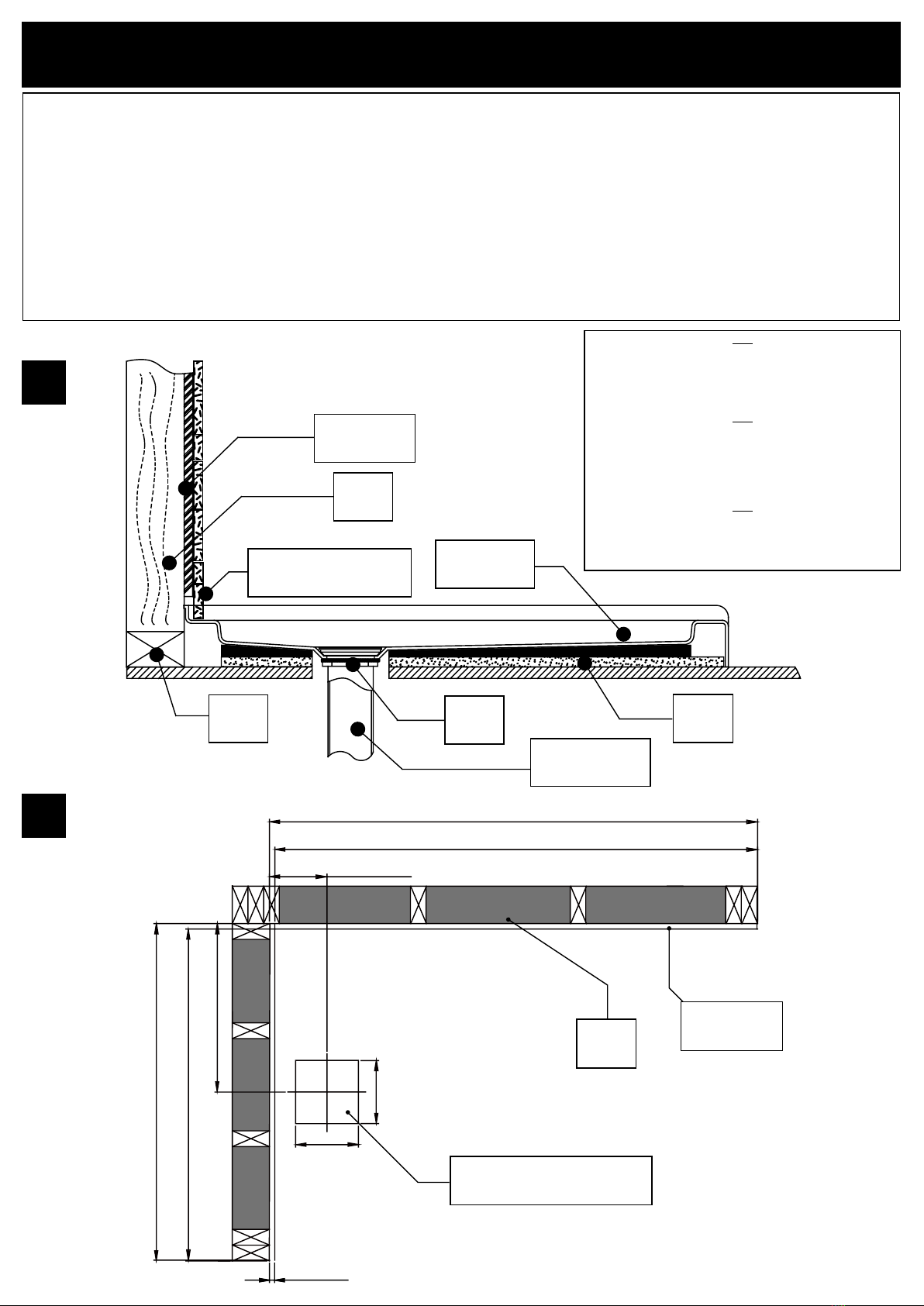
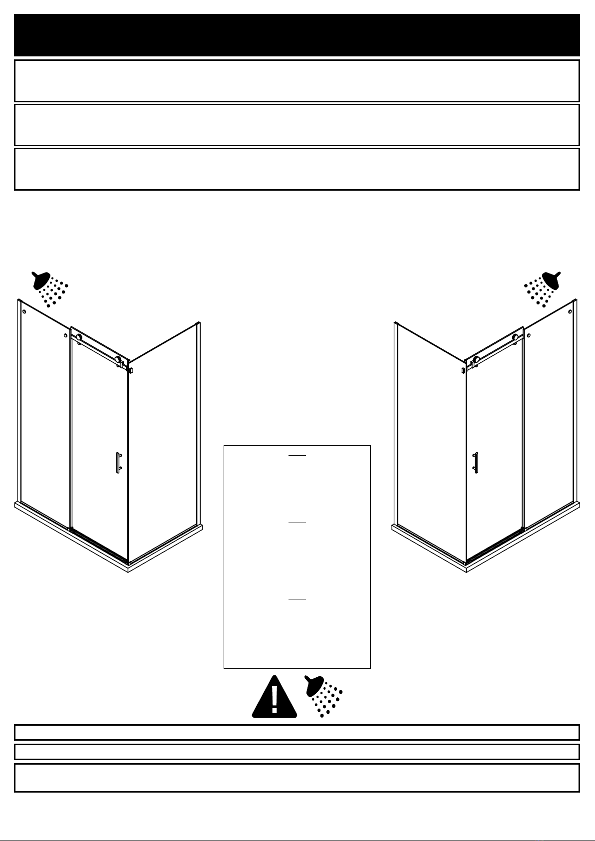
SHOWER DIMENSIONS.....................................3
WALL-TO-WALL DIMENSIONS .........................4
PACKAGE CONTENT ........................................5
PART LIST ..........................................................7
SUPPLIED HARDWARE LIST............................9
TOOLS REQUIRED (not supplied) ...................9
PREPARATION.................................................10
SAFETY INFORMATION .................................. 11
SAFETY NOTICE..............................................12
PREPARATION.................................................12
WALL TRACK INSTALLATION........................13
FIXED PANEL AND SIDE PANEL
INSTALLATION ................................................14
SHOWER DOOR INSTALLATION....................24
SEAL STRIPS INSTALLATION ........................26
HANDLE INSTALLATION.................................27
SEALING ..........................................................28
MAINTENANCE AND CARE ............................29
LIMITED PRODUCT WARRANTY....................30
TABLE DES MATIÈRES .....................................2
DIMENSIONS DE LA DOUCHE .........................3
MESURES MUR-À-MUR ....................................4
CONTENU DE L’EMBALLAGE .........................5
LISTE DES PIÈCES............................................7
QUINCAILLERIE FOURNIE ..............................9
OUTILS REQUIS (non fournis)..........................9
PRÉPARATION ................................................10
INFORMATION SUR LA SÉCURITÉ................ 11
AVIS DE SÉCURITÉ ........................................12
PRÉPARATION ................................................12
INSTALLATION DE LA GLISSIÈRE ................13
INSTALLATION DU PANNEAU FIXE ET DU
PANNEAU LATÉRAL .......................................14
INSTALLATION DE LA PORTE DE DOUCHE.24
INSTALLATION DES BANDES D’ÉTANCHÉITÉ
..........................................................................26
INSTALLATION DE LA POIGNÉE ...................27
SCELLAGE.......................................................28
ENTRETIEN ET MAINTENANCE.....................29
GARANTIE LIMITÉE DU PRODUIT .................30
TABLA DE CONTENIDOS..................................2
DIMENSIONES DE LA DUCHA..........................3
MEDIDAS DE PARED-A-PARED .......................4
CONTENIDO DEL PAQUETE.............................5
LISTA DE PIEZAS...............................................7
CONTENIDO DE HARDWARE...........................9
HERRAMIENTAS NECESARIAS (no incluido) ..
.............................................................................9
PREPARACIÓN ................................................10
INFORMACIÓN DE SEGURIDAD .................... 11
AVISOS DE SEGURIDAD.................................12
PREPARACIÓN ................................................12
INSTALACIÓN DEL RIEL DE PARED..............13
INSTALACIÓN DEL PANEL FIJO Y DEL PANEL
LATERAL .........................................................14
INSTALACION DE LA PUERTA DE DUCHA ...24
INSTALACIÓN DE LAS TIRAS DEL SELLO...26
INSTALACIÓN DE LA MANIJA .......................27
SELLADO .........................................................28
MANTENIMIENTO Y CUIDADO .......................29
GARANTÍA LIMITADA DEL PRODUCTO ........30

PAGE 3
SHOWER DIMENSIONS
DIMENSIONS DE LA DOUCHE
DIMENSIONES DE LA DUCHA
*B*
ATTENTION!
This is the minimum shower width without
cutting the bar. Refer to the Installation
Manual supplied with the shower door for
further adjustment details.
ATTENTION!
Largeur minimale de la douche sans couper
la barre. Voir le manuel d’installation fourni
avec la porte de douche pour plus de
détails sur les ajustements.
¡ATENCIÓN!
Ancho mínimo de la ducha sin cortar la
barra. Consulte el manual de instalación
suministrado con la puerta de la ducha para
obtener más detalles sobre los ajustes.
Measures: inch [millimeter]
Mesures: pouce [millimètre]
Medidas: pulgadas [milímetros]
G
30 3/16” [766]
A
76”[1930]
*B*
47 3/8”[1203]
A
76”[1930]
C
22 5/8”[574]
D
26 7/16”[672]
E
18 7/8”[480]
F
7 1/16”[180]
A
76”[1930]
Measurements
Mesures
Medidas
A
Shower height
Hauteur de la douche
Altura de la ducha
B
Shower width (Min. without cutting the bar)
Largeur de la douche (Min. sans couper la barre)
Ancho de la ducha (Min. sin cortar la barra)
C
Fixed panel width
Largeur du panneau xe
Ancho de panel jo
D
Door panel width
Largeur de la porte
Anchura del panel de la puerta
E
Door opening
Ouverture de la porte
Abertura de la puerta
F
Distance between handle holes
Distance entre les trous de poignée
Distancia entre los oricios de la manija
G
Side panel width
Largeur du panneau latéral
Ancho del panel lateral

PAGE 4
INSTALLATION STRUCTURE OVERVIEW
VUE D’ENSEMBLE DE LA STRUCTURE D’INSTALLATION
VISIÓN GENERAL DE LA ESTRUCTURA DE INSTALACIÓN
1. Before you start the installation of your product consult the illustration 1 below showing a side-view of the completed installation.
2. Illustration 2 shows the recommended wall structure and measurements for the product installation.
NOTE: Customer must follow and comply with the local and national building and plumbing codes. All illustrations in this manual are for reference
only and do not take precedent on any code or regulation. This product should be installed by a professional.
1. Avant de commencer l’installation de votre produit, consultez l’illustration 1 ci-dessous montrant une vue latérale de l’installation terminée.
2. L’illustration 2 montre la structure de paroi recommandée et les mesures pour l’installation du produit.
REMARQUE: Le client doit suivre et se conformer scrupuleusement aux codes locaux et nationaux de construction et de plomberie. Toutes les
illustrations de ce manuel ne sont faites que pour référence et ne prennent aucun précédent sur aucun code ou règlement. Ce produit doit être
installé par un professionnel.
1. Antes de iniciar la instalación del producto, ver Figura 1 muestra una vista lateral de la instalación se haya completado.
2. La gura 2 muestra la estructura de la pared recomendado y medidas para la instalación del producto.
NOTA: El cliente debe seguir y cumplir con los códigos de construcción locales y nacionales y fontanería. Todas las ilustraciones de este manual
son indicativos y se comprometen ningún precedente para cualquier código o reglamento. Este producto debe ser instalado por un profesional.
Drywall
Placoplâtre
Paneles de yeso
Stud
Montant
Soportes
Shower base
Base de douche
Plato de ducha
Cement
Ciment
Cemento
Drain
Drain
Desagüe
Waste pipe
Tuyau d’évacuation
Tubería de desagüe
Stud
Montant
Soportes
Finished Wall (tiles or other)
Mur ni
Pared terminada
FAQ
Q: What thickness of cement must I apply?
A: Between 25 mm and 38 mm (1 in and 1.5 in).
Q: Is the base installed on the studs or on the drywall?
A: On the studs.
FAQ
Q: Quelle épaisseur de ciment dois-je appliquer ?
R: Entre 25 mm et 38 mm (1 po et 1.5 po).
Q: La base est-elle installée sur les montants ou sur les murs de
placoplâtre?
R: Sur les montants muraux.
FAQ
P: ¿Qué espesor de cemento debo aplicar?
R: Entre 25 mm y 38 mm (1 pu y 1.5 pu).
P: ¿Está instalada la base en los soportes o en el panel de yeso?
R: En los soportes.
1
248” [1219]
47 1/2” [1206]
5 1/2” [140]
1/2” [13]
31 1/2” [800]
16” [406]
6” [152]
6” [152]
Drywall
Placoplâtre
Paneles de yeso
Stud
Montant
Soportes
Waste pipe rough-in
Ouverture pour tuyau d’évacuation
Apertura de la tubería de descarga
32” [813]

PAGE 5
PACKAGE CONTENT
CONTENU DE L’EMBALLAGE
CONTENIDO DEL PAQUETE
U
T
W
V
B
F
CD
A
E
J
N
G
H
I
P
K
L
O
Q
R
M
S

PAGE 6
PACKAGE CONTENT
CONTENU DE L’EMBALLAGE
CONTENIDO DEL PAQUETE
U
1x
A
x2
B
x1
C
1x
D
2x
E
1x
F
2x
G
2x
H
2x
I
1x
J
2x
K
1x
L
1x
M
1x
N
2x
O
1x
P
1x
Q
2x
R
1x
S
1x
T
1x
V
1x
W
x1

PAGE 7
PART LIST
LISTE DES PIÈCES
LISTA DE PIEZAS
PART #
# DE PIÈCE
PARTE #
DESCRIPTION
DESCRIPTION
DESCRIPCIÓN
QUANTITY
QUANTITÉ
CANTIDAD
CODE
CODE
CÓDIO
A
Wall track
Glissière
Riel de la pared
2
Satin Nickel / Satiné / Satinado: 99STR1020-WM
Chrome / Chrome / Cromo: 99STR1068-WM
B
Fixed panel
Panneau xe
Panel jo
1
Satin Nickel / Satiné / Satinado: 99SG20013-WM
Chrome / Chrome / Cromo: 99SG3743-WM
C
Support bar anchor
Ancrage pour barre de support
Anclaje de la barra de soporte
1
Satin Nickel / Satiné / Satinado: 99SGC1011-WM
Chrome / Chrome / Cromo: 99SGC1025-WM
D
Shower door stopper
Buttées pour roues
Retenedor de los rodillo
2
Satin Nickel / Satiné / Satinado: 99SDS0002-WM
Chrome / Chrome / Cromo: 99SDS0000-WM
E
Support bar
Barre de support
Barra de soporte
1
Satin Nickel / Satiné / Satinado: 99SGS1011-WM
Chrome / Chrome / Cromo: 99SDS3631-WM
F
Fixed panel bracket
Raccord pour panneau xe
Abrazadera jas de panel
2
Satin Nickel / Satiné / Satinado: 99SGC1013-WM
Chrome / Chrome / Cromo: 99SGC1024-WM
G
Door roller
Roue de la porte
Rodillo de la puerta
2
Satin Nickel / Satiné / Satinado: 99SWE0007-WM
Chrome / Chrome / Cromo: 99SWE0004-WM
H
Door anti-jump peg
Buttées anti-sauts
Cabo anti-saltos
2
Satin Nickel / Satiné / Satinado: 99SWE0005-WM
Chrome / Chrome / Cromo: 99SWE0006-WM
I
Door panel
Porte de douche
Puerta de la ducha
1 99SGD0002-WM
J
Short seal strip
Bande d’étanchéité courte
Tira de sello corto
2 99SRU0063
K
Door handle
Poignée de porte
Manija de la puerta
1
Satin Nickel / Satiné / Satinado: 99SHA1010-WM
Chrome / Chrome / Cromo: 99SHA1013-WM
L
Fixed panel bottom seal strip
Bande d’étanchéité du bas du panneau xe
Tira de sello en la parte inferior del panel jo
199SRU0035
M
Door bottom seal strip
Bande d’étanchéité du bas de la porte
Tira de sello inferior de la puerta
199SRU0028

PAGE 8
PART LIST
LISTE DES PIÈCES
LISTA DE PIEZAS
PART #
# DE PIÈCE
PARTE #
DESCRIPTION
DESCRIPTION
DESCRIPCIÓN
QUANTITY
QUANTITÉ
CANTIDAD
CODE
CODE
CÓDIO
N
Glass panel vertical seal strip
Bande d’étanchéité verticale pour panneau de verre
Tira de sello vertical con panel de vidrio
299SRU0026
O
Sliding door guide (with its rubber tting)
Guide de porte (avec bande d’étanchéité)
Guía de la puerta (con tira de sello)
1
Satin Nickel / Satiné / Satinado: 99SGC1012-WM
Chrome / Chrome / Cromo: 99SGC1026-WM
P
Door panel vertical seal strip
Bande d’étanchéité vertical de la porte
Tira de sello vertical de la puerta
199SRU0027
Q
Decorative cap
Embout décoratif
Capuchones decorativos
2
Satin Nickel / Satiné / Satinado: 99SHW1151-WM
Chrome / Chrome / Cromo: 99SHW0101-WM
R
Decorative track
Rail décoratif
Riel decorativo
1
Satin Nickel / Satiné / Satinado: 99STR1030-WM
Chrome / Chrome / Cromo: 99STR3759-WM
S
Aluminum prole
Prolé d’aluminium
Riel de aluminio
1
Satin Nickel / Satiné / Satinado: 99SGC4047-WM
Chrome / Chrome / Cromo: 99SGC2038-WM
T
Side panel bracket for support bar anchor
Raccord du panneau latéral pour ancrage de la barre de support
Abrazadera del panel lateral para el anclaje de la barra de soporte
1
Satin Nickel / Satiné / Satinado: 99SGC1034-WM
Chrome / Chrome / Cromo: 99SGC4045-WM
U
Side panel
Panneau latéral
Panel lateral
1
Satin Nickel / Satiné / Satinado: 99SGS30001-WM
Chrome / Chrome / Cromo: 99SGS3695-WM
V
Side panel clamp
Serre-joint pour panneau latéral
Abrazadera del panel lateral
1
Satin Nickel / Satiné / Satinado: 99SGC1020-WM
Chrome / Chrome / Cromo: 99SGC4046-WM
W
Side panel bottom seal strip
Bande d’étanchéité du bas du panneau latéral
Tira de sello en la parte inferior del panel lateral
199SRU0061
***
Complete hardware kit
Quincaillerie complete
Todo el hardware
1
Satin Nickel / Satiné / Satinado: 99SHW6071-WM
Chrome / Chrome / Cromo: 99SHW6072-WM

PAGE 9
SUPPLIED HARDWARE LIST
QUINCAILLERIE FOURNIE
CONTENIDO DE HARDWARE
TOOLS REQUIRED (not supplied)
OUTILS REQUIS (non fournis)
HERRAMIENTAS NECESARIAS (no incluido)
Pencil
Crayon
Lápiz
Screwdriver
Tournevis
Destornillador
Drill and drill bits
Perceuse et forets
Taladro con brocas
ø1/8” (3mm) & ø5/16” (8mm)
Level
Niveau
Nivel
Measuring Tape
Ruban à mesurer
Cinta medidora
Silicone
Silicone
Silicona
Rubber mallet
Maillet en caoutchouc
Mazo de goma
Cutter
Exacto
Cuchilla
Safety glasses
Lunettes de Sécurité
Anteojos de seguridad
Ratchet
Clé à rochet
Llave de trinquete
5mm Bit socket
AA
Screw
Vis
Tornillo
ST4x20mm
2+1
Wall Anchor
Ancrage mural
Tarugo
ø8x30mm
8+2
Cap
Capuchon
Capuchón
8x
Fitting
Raccord
Accesorio
8x
Screw
Vis
Tornillo
ST5x30mm
6+2
Allen key
Clé Allen
Llave Allen
2mm & 2.5mm & 5mm
Screw
Vis
Tornillo
ST4x12mm
6+2
Screw
Vis
Tornillo
ST5x35mm
2+1
Cap
Capuchon
Capuchón
2x
Cap
Capuchon
Capuchón
4x
BB
II
HH
GG
FF
EE
DDCC

PAGE 10
A B
FAQ
Q: If the shower head is installed on the
other wall, will it leak?
A: It is possible to install your shower
head on the other side, but we strongly
recommend to install it as illustrated.
FAQ
Q: Y’aura t-il fuite si la pomme de
douche est installée sur l’autre mur?
R: Il est possible d’installer votre
pomme de douche de l’autre côté, mais
nous vous recommandons fortement de
l’installer comme illustré.
FAQ
P: ¿Habrá una fuga si la cabeza de
ducha está instalada en la otra pared?
R: Es posible instalar su cabezal
de ducha en el otro lado, pero le
recomendamos encarecidamente que
lo instale como se muestra.
PREPARATION
PRÉPARATION
PREPARACIÓN
This instruction is drawn up for a door opening from right to left (see illustration A).
For an installation for a door opening from left to right (see illustration B), use the same instructions, but switch
around the panels: mirror eect.
Utilisez ces instructions pour une ouverture de la porte de droite à gauche (illustration A).
Pour une installation de gauche à droite (illustration B), suivez ces mêmes instructions mais permuter l’emplacement
des panneaux: eet miroir.
Estas instrucciones fueron elaboradas para una abertura de puerta de derecha a izquierda (ilustración A).
Para una abertura de izquierda a derecha (ilustración B), siga estas mismas instrucciones, pero cambie el lugar
para la ubicación del riel: efecto espejo.
Install the shower head on the door’s side as shown in the illustration! This will reduce the risk of leaking.
Installez le pommeau de douche du côté de la porte tel qu’illustré, an de diminuer les risques de fuites.
¡Instale la cabeza de la ducha hacia el lado de la puerta como se muestra! Esto reducirá el riesgo de escape de
agua.

PAGE 11
CAUTION
Please carefully read the following important safety information before handling or installing this shower. There is a risk of serious injury while
handling this product. To minimize these risks, please note:
• Always wear safety glasses and gloves while handling.
• Always read and follow all the steps in the installation instructions.
• Inspect all contents and glass for damage before installation.
• Extreme caution should be taken while handling the glass during installation as the tempered glass may shatter if in contact with a hard
surface.
• Handle the tempered glass with caution! Improperly handling the glass can cause it to break suddenly in small pieces (never in pointed
fragments).
• Always take all precautions not to touch the tempered glass with any tools during the installation, or after installed.
• Do not cut or modify the tempered glass as it will shatter if cut.
• Carefully remove product from packaging and keep packaging until installation is complete.
• Inspect all parts for damage; if there is damage to the unit prior to installation, please contact customer service at the number provided in
this guide.
• Install the shower on a oor that is level and able to accommodate the weight of the unit and an occupant.
• Consult local building codes and compliance standards prior to installation and ensure conformity.
• After installation, and from time to time, check the glass for t and nish to ensure that nothing has come loose since installation.
• Keep this installation manual for future reference.
SAFETY INFORMATION
INFORMATION SUR LA SÉCURITÉ
INFORMACIÓN DE SEGURIDAD
AVERTISSEMENT
Veuillez lire attentivement les importantes consignes de sécurité suivantes avant la manutention et l’installation de cette douche. La manipulation
de ce produit présente un risque de blessure grave. Pour minimiser ces risques, veuillez prendre note de ce qui suit:
• Toujours porter des lunettes et des gants de sécurité pendant la manutention.
• Toujours lire et suivre toutes les étapes indiquées dans les instructions d’installation.
• Avant l’installation, inspecter tout le contenu et le verre pour détecter toute forme de dommages.
• Pendant l’installation, faire très attention lorsque vous manipulez les pièces en verre, car le verre trempé peut se fracasser s’il entre en
contact avec une surface dure.
• Manipulez le verre trempé avec précaution sinon il pourrait se briser en petits morceaux (jamais en fragments pointus).
• Prendre toujours toutes les précautions nécessaires pour que, pendant l’installation ou après, les outils que vous utilisez n’entrent pas en
contact avec le verre trempé.
• Ne pas couper ni modier le verre trempé, car il pourrait se briser en éclat s’il est coupé.
• Sortir le produit de son emballage avec soin et le conserver jusqu’à ce que l’installation soit complétée.
• Inspectez toutes les pièces. S’il y a des dommages sur le produit avant l’installation, veuillez communiquer avec le service à la clientèle au
numéro indiqué dans ce guide.
• Installez la douche sur un plancher au niveau et capable de supporter le produit et son utilisateur.
• Veuillez consulter le code du batiment et les normes de conformité avant l’installation du produit.
• Après l’installation, et périodiquement, vérier l’assemblage et la nition des pièces en verre, pour vous assurer qu’aucun élément ne s’est
desserré depuis l’installation.
• Conserver le présent manuel d’instruction pour consultation future.
PRECAUCIÓN
Lea cuidadosamente la siguiente información importante antes de manipular e instalar la ducha. Hay riesgo de lesiones graves mientras se
manipula el producto. Para minimizar estos riesgos, sírvase notar:
• Utilice siempre anteojos de seguridad y guantes durante la manipulación.
• Lea y siga siempre todos los pasos en las instrucciones de instalación.
• Inspeccione todo el contenido y el vidrio por daños antes de la instalación.
• Hay que prestar atención especial mientras se manipula el vidrio durante la instalación ya que el vidrio templado se puede despedazar al
contacto con una supercie dura.
• Manipule el vidrio templado con precaución! Una manipulación inadecuada del vidrio puede ocasionar que se rompa.
• Observe siempre todas las precauciones para no tocar el vidrio templado con ninguna herramienta durante ni después de la instalación.
• No corte el vidrio templado puesto que se despedazará si se corta.
• Retire con cuidado los productos de envase y embalaje mantendrá hasta que la instalación se haya completado.
• Inspeccione todas las piezas en busca de daños, si hay daños en la unidad antes de la instalación, póngase en contacto con el servicio al
cliente al teléfono que gura en esta guía.
• Instale la ducha en un piso que esté nivelado y pueda contener el peso de la unidad y de un ocupante.
• Consulte los códigos de construcción locales y normas requeridas antes de la instalación y asegúrese de cumplirlos.
• Después de la instalación, y de tiempo en tiempo, verique el ajuste el acabado del vidrio para asegurarse de que nada se ha aojado con
el tiempo.
• Guarde este manual de instalación para consulta en el futuro.

PAGE 12
NOTICE
Any modication or alteration from what is specied in this instruction manual will void any and all warranty on this
product.
The distributor is not responsible for any damage to the unit or personal property caused by improper installation. If
you disregard instructional warnings, you will void your warranty and possibly deal with water damage.
Consult the distributor’s website for any additional information or question on this product’s installation.
SAFETY NOTICE
AVIS DE SÉCURITÉ
AVISOS DE SEGURIDAD
AVIS
Toute modication ou altération apportée aux indications données dans le présent manuel d’instructions annule
toute garantie associée à ce produit.
Le distributeur n’est pas responsable pour les dommages sur le produit ou sur la personne causés par une installation
inadéquate. Si vous ne tenez pas compte des indications du manuel d’instruction, vous annulerez votre garantie et
vous vous exposerez à des dommages causés par les fuites d’eau.
Pour de plus amples renseignements sur l’installation du produit ou si vous avez des questions, veuillez consulter
le site du distributeur.
ATENCIÓN
Cualquier modicación o alteración con respecto a lo especicado en este manual de instrucción anulará toda la
garantía de este producto.
El distribuidor no se hace responsable por cualquier tipo de daño a la unidad o propiedad personal ocasionado por
una instalación inadecuada. Ignorar estas instrucciones anulará la garantía y ocasionará daños potenciales por
agua en su hogar.
Consulte el sitio web del distribuidor para cualquier información adicional o pregunta sobre la instalación de este
producto.
PREPARATION
PRÉPARATION
PREPARACIÓN
You will need at least two people to install this unit properly.
Before beginning assembly of product, make sure all parts are present. Compare parts with package contents list
and hardware contents list. If any part is missing or damaged, do not attempt to assemble the product.
2 personnes sont requises pour installer le produit correctement et sécuritairement.
Avant de commencer l’installation du produit, soyez assuré d’avoir toutes les pièces. Comparez les pièces avec les
listes fournies. S’il y a des pièces manquantes ou endommagées, ne tentez pas d’assembler le produit.
Necesitará al menos dos personas para instalar esta unidad de forma adecuada.
Antes de comenzar a ensamblar el producto, asegúrese de tener todas las piezas. Compare las piezas con la lista
del contenido del paquete y la lista de aditamentos. No intente ensamblar el producto si falta alguna pieza o si estas
están dañadas.

PAGE 13
WALL TRACK INSTALLATION
INSTALLATION DE LA GLISSIÈRE
INSTALACIÓN DEL RIEL DE PARED
1.1-1.2. Position the wall tracks (A) as illustrated. Level the tracks (A) and mark the track holes positions.
1.3. Remove the tracks and drill pilot holes in the marked locations with a ø5/16” (8mm) drill bit.
1.4. If there are no studs located behind the wall tracks (A), then insert the wall anchors (AA) using a rubber mallet until the wall anchors are ush with the wall.
1.5. Replace and secure the tracks (A) with screws (BB). Do not overtighten.
1.1-1.2. Positionnez les glissières (A) tel qu’illustré. Mettre les glissières (A) à niveau et marquer l’emplacement des trous.
1.3. Retirez les glissières et percez des trous guides aux endroits marqués avec un foret ø5/16” (8mm).
1.4. S’il n’y a pas de montant mural derrière les glissières (A), alors insérez les ancrages muraux (AA) en utilisant un maillet en caoutchouc.
1.5. Replacez les glissières (A), puis la xer avec les vis (BB). Ne pas serrer trop fortement.
1.1-1.2. Posicionar los rieles (A) como se muestra. Nivele los rieles (A) y marque las posiciones de los agujeros del riel.
1.3. Retire los rieles y perfore los agujeros guía en los sitios marcados con una broca de ø5/16” (8mm).
1.4. Si no hay un soporte de pared detrás los rieles (A), inserte los tarugos (AA) con un mazo de goma hasta que estos queden al ras de la pared.
1.5. Vuelva a colocar y jar los rieles (A) con los tornillos (BB). No los apriete excesivamente.
1
WARNING!
If there are no studs aligned to support bar anchors
behind the drywall, use the wall anchors to ensure the
screws won’t become loose.
AVERTISSEMENT!
s’il n’y a pas de goujons alignés pour soutenir les
ancrages de barre derrière la cloison sèche, utilisez les
ancrages muraux pour vous assurer que les vis ne se
desserreront pas.
¡ADVERTENCIA!
Si no hay postes alineados para apoyar la barra detrás
de las escarpias, utilice los anclajes de la pared para
asegurarse de que los tornillos no se aojarán .
A
ø5/16”
8mm
1 1/4” [30]
BB
AA
1 1/4” [30]
1.1
1.2 1.3
1.4 1.5
1.1

PAGE 14
FIXED PANEL AND SIDE PANEL INSTALLATION
INSTALLATION DU PANNEAU FIXE ET DU PANNEAU LATÉRAL
INSTALACIÓN DEL PANEL FIJO Y DEL PANEL LATERAL
2.1-2.2. Insert the xed panel bottom seal strip (L) on the base of the xed panel (B). Insert the side panel bottom seal strip (W) on the base of the side panel
(U). Cut the surplus part with a cutter.
2.3-2.4. Insert the xed panel (B) into the wall track (A). Insert the side panel (U) into the wall track (A). Do not fully tighten it as further adjustments may be
required.
Note: The wall track (A) allows you to adjust the position of the xed panel (B) and the side panel (U). Adjusting the depth and/or giving the glass
panel a slight angle allows for precise alignment with the door.
2.1-2.2. Insérez la bande d’étanchéité du panneau xe (L) à la base du panneau xe (B). Insérez la bande d’étanchéité du panneau latéral (W) à la base du
panneau latéral (U). Coupez la partie en surplus avec un exacto.
2.3-2.4. Insérez le panneau xe (B) dans la glissière (A). Insérez le panneau latéral (U) dans la glissière (A). Ne pas le xer car vous pourriez apporter de futurs
ajustements.
Note: La glissière (A) permet d’ajuster la position du panneau xe (B) et le panneau latéral (U). Ajustez la profondeur ou/et donner un léger angle au
panneau permet d’obtenir un alignement parfait avec la porte.
2.1-2.2. Inserte la tira de sello en la parte inferior del panel jo (L) en la base del panel jo (B). Inserte la tira de sello en la parte inferior del panel lateral (W) en
la base del panel lateral (U). Corte la parte sobrante con una cuchilla a la longitud adecuada.
2.3-2.4. Inserte el panel jo (B) en el riel de pared (A). Inserte el panel lateral (U) en el riel (A). No lo apriete completamente ya que se puede necesitar más
ajustes.
Nota: El riel de pared (A) le permiten ajustar la posición del panel jo (B) el panel lateral (U). Al ajustar la profundidad y/o al mover el panel hacia un
ligero ángulo se permite una alineación precisa con la puerta.
2
1”[25]
L
C
1”[25]
W
Q
2.22.1
A
U
A
B
2.3 2.4

PAGE 15
FIXED PANEL AND SIDE PANEL INSTALLATION
INSTALLATION DU PANNEAU FIXE ET DU PANNEAU LATÉRAL
INSTALACIÓN DEL PANEL FIJO Y DEL PANEL LATERAL
3
B
O
U
V
3.1 3.2
3.1-3.2. Smoothly slide the sliding door guide (O) at the bottom of the xed panel (B). Smoothly slide the side panel clamp (V) at the bottom of the side panel
(U), but without securing it.
3.1-3.2. Placez le guide de porte (O) au bout du panneau xe (B), Placez le serre-joint pour panneau latéral (V) au bout du panneau latéral (U), mais sans le
sécuriser.
3.1-3.2. Deslice suavemente la guía (O) en la parte inferior del panel jo (B). Deslice suavemente abrazadera del panel lateral (V) en la parte inferior del panel
lateral (U) sin jarla.

PAGE 16
NEXT STEP MAY REQUIRE TO TRIM THE SUPPORT BAR
If the support bar is too long for your wall-to-panel opening “D”, you will have
to trim it down. Below calculation is for reference only: Ensure you made all
the proper measurements before you cut the bar.
ONLY CUT THE BAR ON THE SIDE WITH NO HOLES!
(THE DOOR SIDE)
1. Measure the distance “D” at the height where the bar will be installed.
2. Cut the bar to a total length of L = D - 7/8” (L = D - 22mm).
LA PROCHAINE ÉTAPE PEUT EXIGER DE RÉDUIRE LA BARRE DE SUPPORT
Si la barre de support est trop longue pour votre ouverture «D», elle doit être
coupée. Le calcul ci-dessous est à titre de référence uniquement: S’Assurez
d’avoir eectué toutes les mesures appropriées avant de couper la barre.
SEULEMENT COUPER LA BARRE SUR LE CÔTÉ SANS TROU!
(LE CÔTÉ DE LA PORTE)
1. Mesurer la distance «D» à la hauteur où la barre de support sera installée.
2. Couper la barre à une longueur totale de L = D - 7/8 ”(L = D - 22mm).
EL PRÓXIMO PASO PUEDE REQUERIR REDUCIR LA BARRA DE APOYO
Si la barra de soporte es demasiado larga para su apertura “D”, debe
cortarse. El siguiente cálculo es solo de referencia: asegúrese de haber
completado todas las mediciones apropiadas antes de cortar la barra.
¡SOLO CORTE LA BARRA POR EL LADO SIN AGUJERO!
(EL LADO DE LA PUERTA)
1. Mida la distancia “D” a la altura donde se instalará la barra de soporte.
2. Corte la barra a una longitud total de L = D - 7/8 “(L = D - 22 mm).
L = D - 7/8”
L = D - 22mm
1
D
2
L

PAGE 17
FIXED PANEL AND SIDE PANEL INSTALLATION
INSTALLATION DU PANNEAU FIXE ET DU PANNEAU LATÉRAL
INSTALACIÓN DEL PANEL FIJO Y DEL PANEL LATERAL
4.1. Install the support bar anchor (T) onto the side panel (U).
4.2. Slide the 2 stoppers (D) and the 2 support bar anchors (C & T) onto the support bar (E).
4.3. Install the support bar to the side panel (U).
4.4. Loosely mount the support bar (E) onto xed panel (B) using the brackets (F) and level it.
4.1. Installez l’ancrage pour barre de support (T) sur le panneau latéral (U).
4.2. Glissez les 2 buttées pour roues (D) et les 2 ancrages pour la barre de support (C et T) sur la barre de support (E).
4.3. Installez la barre de support au panneau latéral (U).
4.4. Sans trop serrez, installez la barre de support (E) sur le panneau xe (B) en utilisant les raccords pour panneau xe (F) et mettre à niveau.
4.1. Instale el anclaje de la barra de soporte (T) en el panel lateral (U).
4.2. Deslice los 2 retenedores (D) y los 2 anclajes (C y T) de la barra de soporte sobre la barra de soporte (E).
4.3. Instale la barra de soporte al panel lateral (U).
4.4. Monte la barra de soporte (E) sin apretar en el panel jo (B) utilizando las abrazaderas (F) y nivélela.
4
B
E
F
TU
T
E
DT
D
E
C
U
4.1 4.2
4.3 4.4

PAGE 18
FIXED PANEL AND SIDE PANEL INSTALLATION
INSTALLATION DU PANNEAU FIXE ET DU PANNEAU LATÉRAL
INSTALACIÓN DEL PANEL FIJO Y DEL PANEL LATERAL
5
5.1. Mark the outline of the support bar’s anchor (C) on the wall.
5.2. Mark the position of the guide (O).
5.3. Mark the position of the side panel clamp (V).
5.4-5.5. Completely remove the guide (O) and the support bar (E).
5.1. Marquez le contour de l’ancrage (C) sur le mur.
5.2. Marquez la position le guide de porte (O).
5.3. Marquez la position le serre-joint pour panneau latéral (V).
5.4-5.5. Complètement retirer le guide (O) et la barre de support (E).
5.1. Marque el contorno del anclaje de la barra de soporte (C) en la pared.
5.2. Marque las posiciones de la guía (O).
5.3. Marque las posiciones de la abrazadera del panel lateral (V).
5.4-5.5. Retire completamente el guía (O) y la barra de soporte (E).
5.1
B
O
BO
B
E
F
C
V
5.2
5.3 5.4 5.5

PAGE 19
FIXED PANEL AND SIDE PANEL INSTALLATION
INSTALLATION DU PANNEAU FIXE ET DU PANNEAU LATÉRAL
INSTALACIÓN DEL PANEL FIJO Y DEL PANEL LATERAL
6
6.1. Completely remove the side panel (U).
6.2. Completely remove the xed panel (B).
6.3. Mark the position of hole of the sliding door guide (O).
6.4. Mark the position of hole of the side panel clamp (V).
6.1. Complètement retirer le panneau latéral (U).
6.2. Complètement retirer le panneau xe (B).
6.3. Marquez la position du trou pour le guide de porte (O).
6.4. Marquez la position du trou pour le serre-joint pour panneau latéral (V).
6.1. Retire completamente el panel lateral (U).
6.2. Retire completamente el panel jo (B).
6.3. Marque la posición del agujero de la guía (O).
6.4. Marque la posición del agujero de abrazadera del panel lateral (V).
6.1
O
A
U
AB
V
6.3
6.2
6.4

PAGE 20
V
FIXED PANEL AND SIDE PANEL INSTALLATION
INSTALLATION DU PANNEAU FIXE ET DU PANNEAU LATÉRAL
INSTALACIÓN DEL PANEL FIJO Y DEL PANEL LATERAL
7.1. Drill a pilot hole for the sliding door guide (O) using a ø1/8” (3mm) drill bit.
7.2. Install the sliding door guide (O) with the screw (CC).
7.3. Drill a pilot hole for the side panel clamp (V) using a ø1/8” (3mm) drill bit.
7.4. Install the side panel clamp (V) with the screw (CC).
7.1. Percez un trou pilote pour le guide de porte (O) en utilisant un foret de ø1/8” (3mm).
7.2. Installez le rail de porte (O) avec la vis (CC).
7.3. Percez un trou pilote pour le serre-joint pour panneau latéral (V) en utilisant un foret de ø1/8” (3mm).
7.4. Installez le serre-joint pour panneau latéral (V) avec la vis (CC).
7.1. Perfore un agujero guía para la guía (O) de la puerta corrediza utilizando una broca de ø1/8” (3mm).
7.2. Instale el riel de la puerta (O) con el tornillo (CC).
7.3. Perfore un agujero guía para abrazadera del panel lateral (V) utilizando una broca de ø1/8” (3mm).
7.4. Instale la abrazadera del panel lateral (V) con el tornillo (CC).
7
ø1/8”
3mm
HELPFUL HINT!
Add a drop of silicone in the holes
before inserting the screws.
ASTUCE!
Ajoutez une goutte de silicone dans les
trous avant de visser.
¡CONSEJO!
Añadir una gota de silicona en los
agujeros antes de atornillar.
HH
CC
7.1
HELPFUL HINT!
Add a drop of silicone in the holes
before inserting the screws.
ASTUCE!
Ajoutez une goutte de silicone dans les
trous avant de visser.
¡CONSEJO!
Añadir una gota de silicona en los
agujeros antes de atornillar.
ø1/8”
3mm
7.3 7.4
O
7.2
HH
CC
Other manuals for KELSEY
2
Table of contents
Other OVE Bathroom Fixture manuals

OVE
OVE SWIFT WALL PANEL 36 User manual

OVE
OVE BREEZE B14 User manual

OVE
OVE BREEZE PRO BASE User manual

OVE
OVE 0150560 User manual

OVE
OVE SONOMA 24 User manual

OVE
OVE NIKO 48 3492202 User manual

OVE
OVE NOAH User manual

OVE
OVE BREEZE & PARIS 32 User manual

OVE
OVE NIKO 36 3492203 User manual

OVE
OVE Wexford 48 User manual
Popular Bathroom Fixture manuals by other brands

Delta
Delta H2Okinetic 75506SN quick start guide

WarmlyYours
WarmlyYours Sierra installation manual

Devon & Devon
Devon & Devon Savoy T Assembly instructions

J D Williams
J D Williams New England QN913 Assembly instructions

Delta
Delta Classic 3530LF quick start guide

PierDeco
PierDeco AquaMassage PD-845 owner's manual