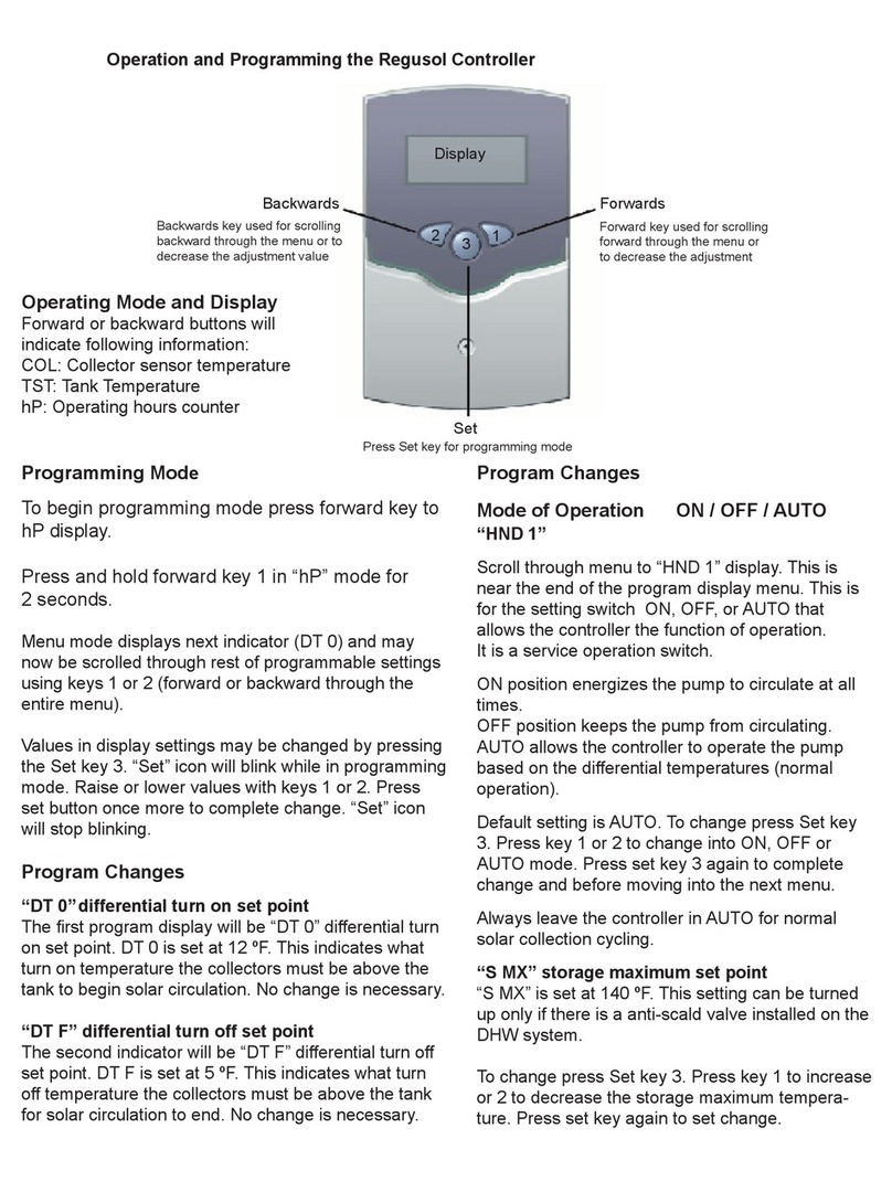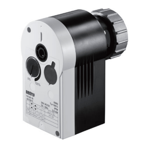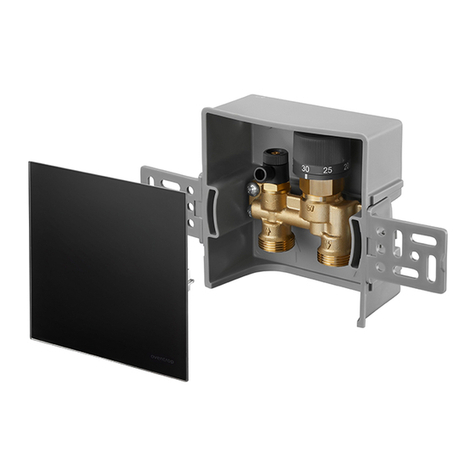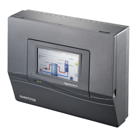
Assembly and Operation Manual REGTRONIC PX
Assembly and Operating Manual 167106181 2 1317BED015-12K-E, Revised 03/2010
REGTRONIC PX
Table of contents:
1
SYMBOLS AND ABBREVIATIONS...................................................................................................................3
2
APPLICATIONS / FEATURES...........................................................................................................................4
2.1
B
ASIC INFORMATION
.....................................................................................................................................4
2.2
A
PPLICATIONS
..............................................................................................................................................4
2.3
U
NIT FEATURES
............................................................................................................................................4
3
SAFETY ADVICE ...............................................................................................................................................5
3.1
E
SSENTIAL SAFETY ADVICE
............................................................................................................................5
3.1.1
Avoiding the risk of explosion ................................................................................................................5
3.1.2
Avoiding a lethal hazard due to electric shocks.....................................................................................5
3.1.3
Avoiding a fire hazard ............................................................................................................................5
3.1.4
Avoiding a risk of injury due to burning..................................................................................................5
3.1.5
Preventing material damage..................................................................................................................5
3.2
S
TRUCTURAL FEATURES OF THE INFORMATION ON DANGERS
...........................................................................6
3.3
S
TRUCTURAL FEATURES OF THE INFORMATION ON MATERIAL DAMAGE AND ENVIRONMENTAL POLLUTION
...........6
4
UNIT INSTALLATION ........................................................................................................................................7
4.1
O
PENING THE UNIT
........................................................................................................................................8
4.2
W
ALL INSTALLATION
......................................................................................................................................8
5
ELECTRICAL CONNECTIONS – OVERVIEW..................................................................................................9
5.1
G
ENERAL CONNECTION GUIDELINES
:............................................................................................................10
5.2
115
V
CONNECTORS
...................................................................................................................................11
5.3
C
ONNECTING SENSORS
...............................................................................................................................11
5.4
S
URGE PROTECTION MODULE
......................................................................................................................11
6
OPERATION / DISPLAY..................................................................................................................................12
6.1
O
VERVIEW OF DISPLAY AND CONTROL BUTTONS
...........................................................................................12
6.2
S
CREEN
.....................................................................................................................................................13
6.3
E
XPLANATION OF ICONS
..............................................................................................................................13
6.4
B
UTTON FUNCTIONS
....................................................................................................................................14
6.5
C
ONTROL UNIT USAGE EXAMPLE
..................................................................................................................15
6.5.1
Changing Target dTon temperature.....................................................................................................15
7
USER MENUS..................................................................................................................................................19
7.1
O
VERVIEW
:
MENU LAYOUT
...........................................................................................................................20
7.2
"I
NFO
"
MENU
........................................................................................................................................21
7.3
"P
ROGRAMMING
"
MENU
........................................................................................................................21
8
CONTROL UNIT FUNCTIONS.........................................................................................................................22
9
DATA INTERFACE - DATASTICK
®
.................................................................................................................22
9.1
D
ATA
S
TICK
®
...............................................................................................................................................22
9.2
D
ATA LOGGING
...........................................................................................................................................22
10
TROUBLESHOOTING......................................................................................................................................24
10.1
R
EPORTABLE FAULTS
..................................................................................................................................24
10.2
N
ON
-
REPORTABLE FAULTS
..........................................................................................................................25
11
TECHNICAL DATA ..........................................................................................................................................26
12
RESISTANCE TABLE PT1000 ........................................................................................................................26
13
OVENTROP CORP. - LIMITED WARRANTY..................................................................................................27
