●This product has been developed / produced for industrial use only.
●This product is suitable for indoor use only.
●Avoid using the product in an explosive atmosphere because this prod-
uct does not have an explosive-proof protective construction.
●Make sure that the power supply is off while wiring.
●Take care that wrong wiring will damage the product.
●Verify that the supply voltage variation is within the rating. Take care that
if a voltage exceeding the rated range or an AC power supply is directly
applied, the sensor may get damaged or burnt.
●If power is supplied from a commercial switching regulator, ensure that
the frame ground (F.G.) terminal of the power supply is connected to an
actual ground.
●In case noise generating equipment (switching regulator, inverter mo-
tor, etc.) is used in the vicinity of this product, connect the frame ground
(F.G.) terminal of the equipment to an actual ground.
●Do not run the wires together with high-voltage lines or power lines or
put them in the same raceway. This can cause malfunction due to in-
duction.
●Do not use during the initial transient time (approx. 0.5 sec.) after the
power supply is switched on.
●Cable extension is possible up to total 10m with 0.3mm2, or more,
cable. However, in order to reduce noise, make the wiring as short as
possible.
●Make sure that stress by forcible bend or pulling is not applied to the
cable joint.
●Since the output does not incorporate a short-circuit protection circuit,
make sure to use this product within the specification and take care
against wrong wiring.
●In case a surge is generated in the used power supply, connect a surge
absorber to the supply and absorb the surge.
●Make sure to use an isolation transformer for the DC power supply. If
an auto-transformer (single winding transformer) is used, this product or
the power supply may get damaged.
●Avoid dust, dirt, and steam.
●Take care that the product does not come in contact with oil, grease or
organic solvents, such as, thinner, etc., strong acid or alkaline.
●This sensor is suitable for indoor use only.
CAUTIONS
8
SPECIFICATIONS
7
Designation Simple wire-saving unit for leak detection sensor
(NPN output type)
Model No. EX-FC1
Connectable sensor NPN output type leak detection sensor (EX-F71, EX-F72,
EX-F61, EX-F62) (Note 1) (Note 2)
Applicable connector SL-CP1
Supply voltage 12 to 24V DC±10 % Ripple P-P 10% or less
Current consumption
50mA or less (for one unit)
135mA or less (including the sensor input current when all
outputs are ON)
Output
Relay contact 1a
• Switching capacity: 30V 1A DC (resistant load)
• Min. applied load: 10mV 10μA DC
• Electrical lifetime: 100,000 times or more
(rated load, switching frequency 20 times/min.)
• Mechanical lifetime: 50,000,000 times or more
(switching frequency 180 times/min.)
Output operation
The output relay is ON when the input signal from the sensor is ON.
Response time 5ms or less (excluding the response time of the sensor)
Input points 8 points
Ambient temperature -10 to +60ºC (No dew condensation or icing allowed)
Storage: -20 to +70ºC
Ambient humidity 35 to 85% RH, Storage: 35 to 85% RH
Material Enclosure: ABS, Terminal part: PBT
Cable 0.2mm24-core cabtyre cable, 2m long
Weight Approx. 85g
Accessory SL-CP1 (Snap male connector): 8 pcs.
MS-SL-2 (Unit mounting base): 1 pc.
Notes: 1) PNP output type sensor (including leak detection sensor) cannot be connected.
10101 2) Ordinary sensor (NPN output type) or no-voltage contact output sensor can be
connected.
INTENDED PRODUCTS FOR CE MARKING
9
●The models listed under “ SPECIFICATIONS” come with
CE Marking.
As for all other models, please contact our ofce.
●Contact for CE
Panasonic Marketing Europe GmbH Panasonic Testing Center
Winsbergring 15, 22525 Hamburg,Germany
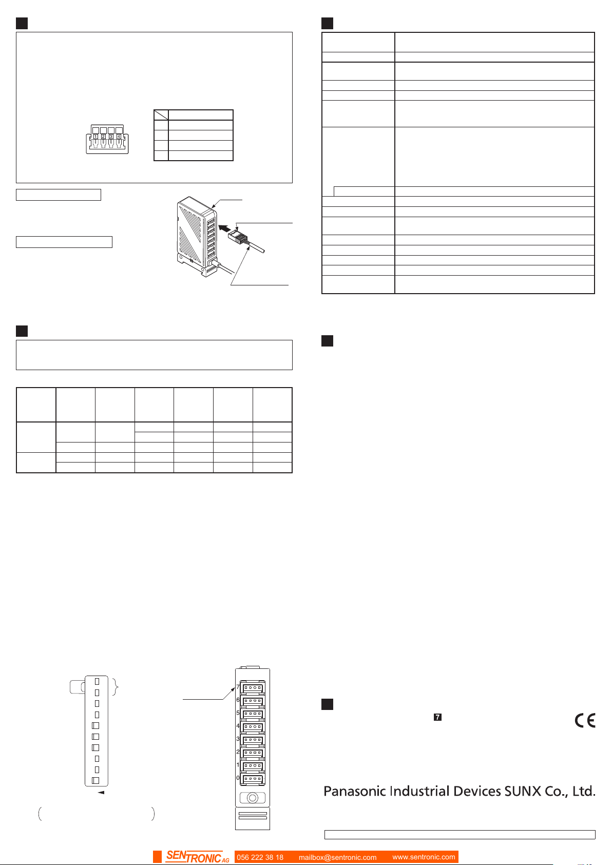
CONNECTION
5
●PNP output type sensor (including leak detection sensor)cannot be
connected.
●Make sure to connect or disconnect the snap male connector (SL-CP1)
in the power supply off condition.
●Take care that wrong wiring will damage the product.
●The terminal No. 4 of the snap male connector (SL-CP1) is not used.
Take care not to connect to the terminal No. 4 by mistake. Further, if
there are unused wires, please insulate them.
123 4
Content
1 +V
2 0V
3 IN
4 No connected
●For details of the hook-up method of the snap male connector (SL-CP1),
refer to the Instruction Manual enclosed with SL-CP1.
Connection method
1. By holding the SL-CP1 with the cable
connected, insert it into the connector
of the EX-FC1 reliably till it stops.
Note: Do not pull out by holding the cable, as this
can result in cable disconnection.
7
6
5
4
3
2
1
0
SL-CP1
Sensor cable
Disconnection method
2. By holding SL-CP1, pull it from the
EX-FC1 horizontally.
CONNECTION SETTING SWITCH
6
The connection setting should be carried out in the power supply off condi-
tion after removing any electrostatic charge which may be present on your
body.
●Operation matrix for each indicator
Operation
Connection
state of the
leak detec-
tion sensor
State of the
connection
setting
switch
Leak
detected
condition
Normal
indicator
(Green)
Error
indicator
(Red)
Output
indicator
(Orange)
Normal
Connected
ON
Not leaked
Lights up Turns off Lights up
Leaked Turns off Lights up Turns off
Unconnected
OFF
-
Turns off Turns off Lights up
Error
Connected
OFF
Not leaked
Lights up Lights up Turns off
Unconnected
ON
-
Turns off Lights up Turns off
●For the channel that the unit sensor is connected to and the connection
setting switch is set to “ON” side, the error indicator (red) lights up for a
moment when the power is turned on. This is not a malfunction for the
unit because it is caused by characteristic of the sensor.
●Make sure to set the connection setting switch with the connector No. to
which the leak detection sensor is connected, to “ON” side.
●In case both the normal indicator (green) and the error indicator (red)
light up, the connection setting switch with the connector No. to which
the leak detection sensor is connected, is not set to “ON” side. Set the
connection setting switch with the connector No. to which the leak detec-
tion sensor is connected, to “ON” side.
●In case the error indicator (red) lights up, the leak detection sensor de-
tects leak or the connection setting switch is set to “ON” side without
connecting the leak detection sensor. If the connection setting switch is
set to “ON” side without connecting the leak detection sensor, set the
connection setting switch to “OFF” side.
●If the leak detection sensor detects leak or the connection setting switch
is set to “OFF” side in the state that the leak detection sensor is improp-
erly mounted to the mounting bracket, the sensor judges as the output is
ON. Be careful when setting.
NOT
USED
7
6
5
4
3
2
1
0
ON
These are not used.
“ON” side
“ON” side
“ON” side
“ON” side
Connection setting switch setting example
In case the input of 0, 3, 4 and 5 are set
to effective.
Connector No.
https://panasonic.net/id/pidsx/global
Overseas Sales Division (Head Ofce)
2431-1 Ushiyama-cho, Kasugai-shi, Aichi, 486-0901, Japan
Phone: +81-568-33-7861 FAX: +81-568-33-8591
For sales network, please visit our website.
PRINTED IN JAPAN © Panasonic Industrial Devices SUNX Co., Ltd. 2018
056 222 38 18 mailbox@sentronic.com www.sentronic.com
SENTRONIC AG


 User manual")


 User manual")


