4. Removetheswitchcoverandcongurethe
communication settings. For the detailed
setting procedure, refer to " 6COMMUNI-
CATION SETTINGS".
Switch cover
After configuring the " 6COMMUNICATION SETTINGS", attach end plates
MS-DIN-E (optional).
5. Reattachtheswitchcoverafterconguring
the communication settings, and attach the
endplates(optional)withtheatsidefacing
in so as to enclose the connected units at
the ends.
6. Tighten the screws to fasten the end plates.
End plate (Option)
End plate (Option)
Note: Be sure to keep the connector cover you removed from the controller.
Removal procedure
1. Loosen the screws on the end plates and
remove the end plates.
2. Slide and remove the product and controllers.
Slide
6COMMUNICATION SETTINGS
●After changing the settings, always turn the power OFF and then ON.
●For the communication conditions and commands, refer to the "SC-HG1-CEF
User's Manual".
● Followtheprocedurebelowtoconguresettings.
Procedure
1. Connect this product to the controller. [Do not attach end plates MS-DIN-E (op-
tional).]
2. With the power OFF, set the mode switch to Network No. setting
mode.
3. Turn ON the power. When the unit starts, the STS1 indicator
(Green) blinks.
4. Set the network number with the Station No. / Network No. setting
switch. The setting range for network numbers is 1 to 239 (decimal).
(0 and 240 or higher will result in an error)
Set the network number in hexadecimal.
●The "×1" switch sets the 1st digit of the station number. 0 to F
(hex) are valid.
●The "×16" switch sets the 2nd and following digits of the sta-
tion number. 0 to E (hex) are valid.
Example: To set to "239" (decimal), set to "EF" (hex).
5. Switch the mode switch to OFF. The network number is written
to the product. When the number is saved in the product, the
STS1 indicator (green) changes from blinking to solidly lit
.
6. Turn OFF the power.
7. Set the mode switch to normal mode.
8. Set the station number with the Station No. / Network No. setting
switch. The setting range for the station number is 1 to 120 (dec-
imal). (0 and 121 or higher: Error)
Set the station number in decimal.
●The "×1" switch sets the 1st digit of the station number. 0 to 9
(decimal) are valid.
●The "×10" switch sets the 2nd and following digits of the sta-
tion number. 0 to C are valid. (A = 10, B = 11, C = 12.)
Example: To set to "119" (decimal), set to "B9".
7CONNECTING AN EXTERNAL DEVICE
Ethernet cable connection
●Make sure that the power supply is OFF while performing wiring work.
●For the Ethernet cable, use a cable recommended by CC-Link Partners Associa-
tion.
● Thecommunicationdistancemustbewithinthespeciedrange.
●Make there is no duplication when setting station numbers.
●Always run the Ethernet cable through a conduit or secure the cable with clamps.
If not secured as indicated above, looseness or movement of the cable or unex-
pected tension on the cable may damage the CC-Link IE Field host device, this
product, or the cable, and cable connection failure may cause malfunctioning.
●Fordetailedconnectionspecications,checktheCable Wiring Manualthatis
published by the CC-Link Partner Association.
How to connect
1. Grasp the Ethernet cable connector and align the
lock release lever with the slot in Port1 or Port2.
2. Insert the connector until you hear a "click"
sound..
This product
Lock release lever
Slot
Removal procedure
1. Press on the lock release lever on the Ethernet
cable and pull out.
Note: Attempting to pull out the connector without pressing the lock re-
lease lever may cause the lock release lever to break.
Do not use
an Ethernet cable if the lock release lever is broken Do not grasp
the cable to pull, as this may cause wire breakage in the cable.
Lock release lever
Network wiring example
CC-Link IE Field
Host device
Station
No. 1
Station
No. 2
Station
No. 3
<Line type>
CC-Link IE Field
Host device
Station
No. 1
Station
No. 2
HUB
Station
No. 3
<Star type>
CC-Link IE Field
Host device
Station No. 1
Station No. 2
Station No. 3
<Ring type>
Note: Mixing of line and star types is possible.
8SPECIFICATIONS
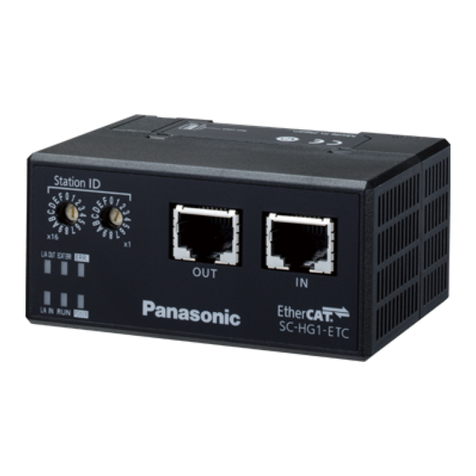
Product name CC-Link IE Field Communication Unit for HG Series
Model SC-HG1-CEF
Compatible sensor units HG-SC□
Number of units connectable Maximum of 15 sensor units (one master, 14 slaves) per SC-HG1-CEF unit
Supply voltage (Note 1) 24V DC ±10%, including 0.5V ripple (P-P)
Current consumption 200mA or less
Communication method CC-Link IE Field
Station type Remote device station
Transmission line types Line, star (mixing of line and star types is possible), ring
Network No. setting 1 to 239 (decimal) [1 to EF (hex)] (0 and 240 or higher result in an error) (Note 2)
Station No. setting 1 to 120 (decimal) (0 and 121 or higher result in an error)
Communication speed 1Gbps
Maximum overall cable
distance 100m
Ambient temperature -10 to +45°C (No condensation or icing), Storage: -20 to +60°C
Ambient humidity 35 to 85% RH, Storage: 35 to 85% RH
Material Unit case: Polycarbonate
Weight Approx. 100g
Notes: 1) Power is supplied from a connected controller / master controller.
2) For the Network No. setting of this product, set a value converted to hexadecimal.
9Cautions
●This product has been developed / manufactured for industrial use only.
●
Verifythatuctuationsofpowerinputsupplyvoltagedonotexceedtherating,in-
cluding controllers.
●
When noise generating equipment (switching regulator, inverter motor, etc.) is
used in the vicinity of this product, ground each frame ground (F.G.) terminal on
the equipment individually.
●Make sure that the power is OFF while performing wiring or connection work.
●Risk of damage and burning if the load is incorrectly wired or short-circuiting occurs.
●Do not wire in parallel with a high-voltage line or power line, or run through the
same conduit. Risk of malfunctioning due to induction.
●This product is suitable for indoor use only.
●Avoid dust, dirt, and steam.
●Do not use in locations where there are corrosive or other harmful gases.
●Ensure that the product does not come into contact with organic solvents such as thinner.
●Ensure that the product does not come into contact with strong acid or alkaline.
●Ensure that the product does not come into contact with oil or grease.
● Thisproductcannotbeusedinanenvironmentthatcontainsammableorexplo-
sive gases.
● Performancemaynotbesatisfactoryinastrongelectromagneticeld.
●Do not drop or otherwise subject to shock. Risk of product damage.
●Do not apply stress such as excessive bending or pulling to an Ethernet cable and
connector base. Risk of damage and malfunctioning due to connection failure.
●Never attempt to disassemble, repair, or modify the product.
●When the product becomes unusable or unneeded, dispose of the product appro-
priately as industrial waste.
●Design the system to allow the addition of external safety circuits and other
means of protection against system trouble.
http://panasonic.net/id/pidsx/global
Overseas Sales Division (Head Ofce)
2431-1 Ushiyama-cho, Kasugai-shi, Aichi, 486-0901, Japan
Phone: +81-568-33-7861 FAX: +81-568-33-8591
For sales network, please visit our website.
PRINTED IN JAPAN © Panasonic Industrial Devices SUNX Co., Ltd. 2017
