manuals.online logo
Brands
  1. Home
  2. •
  3. Brands
  4. •
  5. Panasonic
  6. •
  7. Control Unit
  8. •
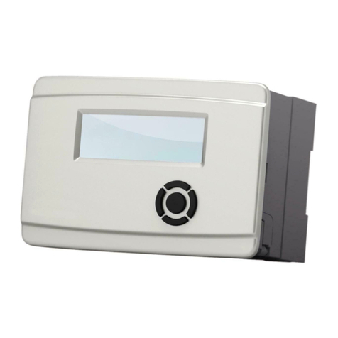
  9. Panasonic SF4D Series User manual

Panasonic SF4D Series User manual

QUICK INSTRUCTION MANUAL
Communication Module for the SF4D Series SF4D-TM1
CME-SF4DTM1 No.0070-83V
Thank you very much for purchasing this Panasonic product.
Please read this Instruction Manual carefully and thoroughly for the correct and opti-
mum use of this product.
Kindly keep this manual in a convenient place for quick reference.
●This document is a quick reference guide to the functions and connections of the
device. The device can be used with a PC (computer) to set the various functions
of a light curtain.
For detailed information, visit “our website (https://panasonic.net/id/pidsx/global)”.
●Manuals are available in the following languages on our website.
Japanese, English, Chinese, Korean, French, German, Spanish, Polish, Italian
1SAFETY CAUTIONS Always observe
●This section explains important rules that must be observed to prevent human in-
jury and property damage.
■The hazards that may occur if the product is used incorrectly are described and
classied by level of harm.
WARNING Risk of death or serious injury.
CAUTION
Risk of minor injury or property damage.
● Use this device as per its specications. Do not modify this device since its func-
tions and capabilities may not be maintained and it may malfunction.
●This device has been developed / produced for industrial use only.
●This product is suitable for indoor use only.
●Use of this device under the following conditions or environments is not presup-
posed. Please consult us if there is no other choice but to use this device in such
an environment.
1) Operating this device under conditions or environments not described in this
manual.
2) Using this device in the following elds: nuclear power control, railroad, aircraft,
auto mobiles, combustion facilities, medical systems, aerospace development,
etc.
●Note that this device may be damaged if it is subject to a strong shock (if it is
dropped onto the oor, for example).
●In case of disposal, dispose this device as an industrial waste.
WARNING
♦Machine designer, installer, employer and operator
• The machine designer, installer, employer and operator are solely responsible
to ensure that all applicable legal requirements relating to the installation and
the use in any application are satised and all instructions for installation and
maintenance contained in the instruction manual are followed.
• Whether this device functions as intended to and systems including this de-
vice comply with safety regulations depends on the appropriateness of the ap-
plication, installation, maintenance and operation. The machine designer, in-
staller, employer and operator are solely responsible for these items.
♦Engineer
• The engineer would be a person who is appropriately educated, has wide-
spread knowledge and experience, and can solve various problems which
may arise during work, such as a machine designer, installer or employer etc.
♦Operator
• The operator should read this instruction manual thoroughly, understand its
contents, and perform operations following the procedures described in this
manual for the correct operation of this device.
• In case this device does not perform properly, the operator should report this
to the employer and stop the machine operation immediately. The machine
must not be operated until correct performance of this device has been con-
rmed.
♦Environment
• Do not use a mobile phone or a radio phone near this device.
• Do not install this device in the following places:
1) A location exposed to direct sunlight
2) A location where condensation may form due to sudden changes of tem-
perature
3) A location where there are corrosive or combustible gases
4) A location with signicant dirt, metal powder, or salt
5) A location where organic solvents such as benzene, paint thinner or alco-
hol, or strong alkaline substances such as ammonia or caustic soda, may
come in contact with the device or are present in the air.
6) A location with signicant steam or dust, a location subject to vibration or
shock, or a location where water droplets may come into contact with the
device.
7) A location near high-voltage lines, high-voltage equipment, power lines,
power equipment, equipment with an amateur radio transmitter, or equip-
ment that generates large switching surges (minimum 100mm)
♦Other matters
• Never modify this device. Risk of impaired device functionality and death or
serious injury.
CAUTION
The device cannot be used in a continuous connection with the light curtain.
2STANDARDS / REGULATIONS
●This product complies with the standards / regulations below.
<European Directives>
EMC Directive
3CONTENTS OF PACKAGE
Controller 1 pc.
Quick Instruction Guide (Japanese, English, Chinese) 1 pc. each.
General Information for Safety, Compliance, and Instructions (23 languages) 1 pc.
4OVERVIEW
●This device is a communication module that is used to copy function settings in a
light curtain and to initialize the device.
●This device can be used with a computer to set various functions of a light curtain.
You can also check and change the settings of various functions (muting, blank-
ing, etc.), and monitor the intensity of received light.
5DESCRIPTION OF PARTS
1
2
3
4
5
6
11
12
10
9
7
8
Name Function
1Power indicator (Green) Lights when the device is connected to a light curtain. Blinks when the de-
vice is only connected to a PC.
2Data indicator (Orange) Lights when data is saved if copy protect is invalid.
Blinks when data is saved if copy protect is valid.
3READ indicator (Orange) Lights when the READ key is pressed. Blinks during communication to read
data.
4READ key Press to read data.
5ENTER key Press to execute a setting or function.
6Strap holder Use this holder when using a strap (purchase separately).
7Mini USB connector For connection to a PC.
8Version Version information of this product.
9WRITE key Press to write data.
10 WRITE indicator (Orange) Lights when the WRITE key is pressed. Blinks during communication to write
data.
11 ERROR indicator (Yellow) Lights when an error occurs.
12 Connection cable (1.5m) For connection to a light curtain.
6CONNECTION
●The device can be connected to the light curtain even when the light curtain pow-
er is ON. To prevent short-circuiting caused by tools or refuse, it is recommended
that the work be performed with the power OFF.
Connecting to a light curtain
1. Make sure that the light curtain power is OFF, and remove the indicator cover.
Indicator cover
Light curtain
2. Connect the device's connection cable to the connector inside the light curtain.
Connection cable
Connector
3. Turn ON the light curtain power.
4. The device starts up.
Disconnecting from the light curtain
1. Turn OFF the light curtain power.
2. Remove the device's connection cable from the connector inside the light curtain.
3. All indicators on the device turn OFF.
4. Attach the indicator cover on the light curtain.
Tighten to a torque of 0.3N·m or less.
CAUTION
There is packing on the indicator cover. If the packing is not tted on the cover
properly, t as shown below before attaching to the device.
Connecting to a PC
1.
Connect the device to a PC with a USB 2.0 cable (A: miniB) (purchase separately).
USB 2.0 cable (A: miniB)
(Purchase separately)
The device
2. The device starts up.
Disconnecting from a PC
1. Disconnect the USB cable at the device or at the PC.
2. All indicators on the device turn OFF.
Connecting to a light curtain and a PC
1. Make sure that the light curtain power is OFF, and remove the indicator cover.
Indicator cover
Light curtain
2. Connect the device's connection cable to the connector inside the light curtain.
Connection cable
Connector
3.
Connect the device to a PC with a USB 2.0 cable (A: miniB) (purchase separately).
USB 2.0 cable (A: miniB)
(purchase separately)
The device
4. The device starts up.
5. Turn ON the light curtain power.
Disconnecting from the light curtain and the PC
1. Turn OFF the light curtain power.
2. Remove the device's connection cable from the connector inside the light curtain.
3. Disconnect the USB cable at the device or at the PC.
4. All indicators on the device turn OFF.
5. Attach the indicator cover on the light curtain.
Tighten to a torque of 0.3N·m or less.
CAUTION
There is packing on the indicator cover. If the packing is not tted on the cover
properly, t as shown below before attaching to the device.
7FUNCTIONS
●The device is equipped with the functions described below.
Copy function
●This function “reads” the settings in one light curtain and “writes” the settings to
another light curtain.
<READ>
• This function reads the settings and log information in a light curtain and saves
the information in the device’s memory.
<WRITE>
• This function writes settings saved in the device to a light curtain.
Saved data initialization function
●This function initializes the settings and log information saved in the device.
I/F communication function
●This function converts the RS-485 communication of the light curtain to the USB
communication of the PC (and vice-versa).
8OPERATION
Copy function / read function (READ)
Procedure
State Description
1
Connect the device's connection cable to the connec-
tor inside the light curtain.
All indicators light for about one second.
2
Indicators other than the power indicator (green) turn
OFF.
[If data is saved in the device, the data indicator (or-
ange) also remains ON.]
3Press the READ key for at least 2 seconds.
4The READ indicator (orange) lights up.
5
Press the ENTER key within 5 seconds.
To cancel “READ”, press any key other than the EN-
TER key.
6
The READ indicator (orange) blinks and reading starts.
The control output (OSSD1 / 2) of the light curtain
turns OFF.
7
The READ indicator (orange) turns OFF and the data
indicator (orange) lights up.
The settings and log information of the connected light
curtain are copied to the device.
8Remove the device's connection cable from the con-
nector inside the light curtain.
Copy function / Write function (WRITE)
Procedure
State Description
1
Connect the device's connection cable to the connec-
tor inside the light curtain.
All indicators light for about 1 second.
2Indicators other than the power indicator (green) and
data indicator (orange) turn OFF.
3Press the WRITE key for at least 2 seconds.
4The WRITE indicator (orange) lights up.
5
Press the ENTER key within 5 seconds.
To cancel “WRITE”, press any key other than the EN-
TER key.
6
The WRITE indicator (orange) blinks and writing starts.
The control output (OSSD1 / 2) of the light curtain
turns OFF.
7
The WRITE indicator (orange) turns OFF.
The settings saved in the device are written to the light
curtain.
8Remove the device's connection cable from the con-
nector inside the light curtain.
Note: Data written with the copy function may be lost due to external causes. After copying settings, check the opera-
tion of the light curtain before use.
Saved data initialization function
Procedure
State Description
1
Connect the device's connection cable to the connec-
tor inside the light curtain.
All indicators light for about 1 second.
2Indicators other than the power indicator (green) and
data indicator (orange) turn OFF.
3Press the READ key and WRITE key at the same time
for at least 2 seconds.
4The READ indicator (orange) and WRITE indicator
(orange) light up.
5
Press the ENTER key within 5 seconds.
To cancel “INITIALIZE”, press any key other than the
ENTER key.
6
The data indicator (orange) turns OFF.
The settings and logs saved in the device are erased
and initialized.
7Remove the device's connection cable from the con-
nector inside the light curtain.
9TROUBLESHOOTING
Problem Cause Solution
All indicators are turns OFF Connector not connected se-
curely. Connect the connector rmly.
The ERROR indicator (yel-
low) blinks and data cannot
be read.
Sensor communication error.
(Noise or communication cir-
cuit failure)
Check the ambient noise conditions near the device.
The ERROR indicator (yel-
low) and data cannot be writ-
ten.
Data is not saved. The data was not saved, so read the data from the
source and write to the device again.
You used the write function in
a different light curtain con-
guration.
Make sure the data conguration matches the con-
guration of the connected light curtain.
Copy protection is in e󰀨ect.
If the data indicator (orange) is blinking, writing is
prohibited (copy protection).
Use the Congurator Light Curtain software to can-
cel copy protection.
Sensor communication error.
(Noise or communication cir-
cuit failure)
Check the ambient noise conditions near the device.
The ERROR indicator (yel-
low) is lit.
The saved data is corrupted.
The saved data is corrupted, so initialize the device.
Read the data from the source and write to the de-
vice again.
Internal failure. If the ERROR indicator (yellow) does not turn OFF
after you initialize the device, replace the device.
The data indicator (orange)
does not turn OFF and data
cannot be initialized.
Internal failure. Replace the device.
I wrote settings to the light
curtain but the settings are
not applied.
Turn the power ON again. Turn ON the light curtain power again.
Power supply break, wire
break, etc. Repeat the write.
During optical synchroniza-
tion, only the emitter or only
the receiver wrote data.
If the light curtain is congured by optical synchroni-
zation, perform read/write to both the emitter and re-
ceiver.
10
SPECIFICATIONS
Product name Communication module for SF4D Series
Model No. SF4D-TM1
Communication method Light curtain: RS-485 bidirectional communication (dedicated protocol)
PC (computer): USB
Protective structure IP40 (IEC)
Ambient temperature -10 to +55°C (No condensation or icing), Storage: -25 to +60°C
Ambient humidity 30 to 85% RH, Storage: 30 to 95% RH
Elevation 2,000m or less (Note:1)
Connection method USB: Mini B male, cable with connector (1.5m)
Weight (main unit only) Approx. 75g
Notes: 1) Do not use or store in an environment that has been pressurized to an air pressure higher than the atmo-
spheric pressure at 0m.
2) If the SF4D Ver3.0 product is used with this product, restrictions will apply to the version of this product.
When using the SF4D Ver. 3.0 product with this product, use this product of Ver.2.0 or later.
11
DIMENSIONS (Units: mm)
20.4 7
37.2
96.3
46
(0.6)
15.4
ø3.7 cable
Panasonic Industrial Devices SUNX Co., Ltd.
https://panasonic.net/id/pidsx/global
Please visit our website for inquiries and about our sales network.
PRINTED IN JAPAN © Panasonic Industrial Devices SUNX Co., Ltd. 2020

Other manuals for SF4D Series

2

This manual suits for next models

1

Other Panasonic Control Unit manuals

Panasonic SL-PC104 User manual

Panasonic

Panasonic SL-PC104 User manual

Panasonic AKHCU200 User manual

Panasonic

Panasonic AKHCU200 User manual

Panasonic CF-BAT0256U User manual

Panasonic

Panasonic CF-BAT0256U User manual

Panasonic PAN4620 Quick setup guide

Panasonic

Panasonic PAN4620 Quick setup guide

Panasonic PAN1326C Owner's manual

Panasonic

Panasonic PAN1326C Owner's manual

Panasonic PAN1326C2 User manual

Panasonic

Panasonic PAN1326C2 User manual

Panasonic CF-BAD02GU User manual

Panasonic

Panasonic CF-BAD02GU User manual

Panasonic CZ-280PAH1 User manual

Panasonic

Panasonic CZ-280PAH1 User manual

Panasonic AK-UCU500P User manual

Panasonic

Panasonic AK-UCU500P User manual

Panasonic KX-T7603X User manual

Panasonic

Panasonic KX-T7603X User manual

Panasonic ELC500 User manual

Panasonic

Panasonic ELC500 User manual

Panasonic GPKS822H - COLOR CAMERA HEAD User manual

Panasonic

Panasonic GPKS822H - COLOR CAMERA HEAD User manual

Panasonic CF-BAD04GU User manual

Panasonic

Panasonic CF-BAD04GU User manual

Panasonic YEP0PTA184 User manual

Panasonic

Panasonic YEP0PTA184 User manual

Panasonic WVPS154 - CAMERA DRIVE UNIT User manual

Panasonic

Panasonic WVPS154 - CAMERA DRIVE UNIT User manual

Panasonic CF-BAS04GU User manual

Panasonic

Panasonic CF-BAS04GU User manual

Panasonic GP-KS162CUDE User manual

Panasonic

Panasonic GP-KS162CUDE User manual

Panasonic CF-BAP0256U User manual

Panasonic

Panasonic CF-BAP0256U User manual

Panasonic INDUSTRY PAN9028 User manual

Panasonic

Panasonic INDUSTRY PAN9028 User manual

Panasonic FP-XH M8N16PD User manual

Panasonic

Panasonic FP-XH M8N16PD User manual

Panasonic WX-CC412BP User manual

Panasonic

Panasonic WX-CC412BP User manual

Panasonic GP-KH232CUE User manual

Panasonic

Panasonic GP-KH232CUE User manual

Panasonic WVPS11B - CAMERA DRIVE UNIT User manual

Panasonic

Panasonic WVPS11B - CAMERA DRIVE UNIT User manual

Panasonic eUniStone Guide

Panasonic

Panasonic eUniStone Guide

Popular Control Unit manuals by other brands

Keba Kemro MM 240/A Project engineering manual

Keba

Keba Kemro MM 240/A Project engineering manual

ProSoft Technology ControlLogix MVI56E-SMGC user manual

ProSoft Technology

ProSoft Technology ControlLogix MVI56E-SMGC user manual

DHI MIKE 3 Flow Model FM user guide

DHI

DHI MIKE 3 Flow Model FM user guide

Dataforth PWRM10-01 quick start guide

Dataforth

Dataforth PWRM10-01 quick start guide

Behringer MIX-SEQUENCER MODULE 1050 quick start guide

Behringer

Behringer MIX-SEQUENCER MODULE 1050 quick start guide

ASAHI YUKIZAI Dymatrix AVHPRS user manual

ASAHI YUKIZAI

ASAHI YUKIZAI Dymatrix AVHPRS user manual

Click Lighthouse ClickSmart user manual

Click Lighthouse

Click Lighthouse ClickSmart user manual

Texas Instruments TPS61020EVM user guide

Texas Instruments

Texas Instruments TPS61020EVM user guide

Cabletron Systems SmartSwitch 6000 Installation & user guide

Cabletron Systems

Cabletron Systems SmartSwitch 6000 Installation & user guide

Hilti SI-AT-A22 Original operating instructions

Hilti

Hilti SI-AT-A22 Original operating instructions

Valon 5009a Operation manual

Valon

Valon 5009a Operation manual

LOGIC RAIL Grade Crossing Pro/2 instructions

LOGIC RAIL

LOGIC RAIL Grade Crossing Pro/2 instructions

Shenzhen TOPWAY LMB162ABC user manual

Shenzhen TOPWAY

Shenzhen TOPWAY LMB162ABC user manual

Johnson Controls Tyco TJPX0500003 manual

Johnson Controls

Johnson Controls Tyco TJPX0500003 manual

Pioneer SCU-2456ZRN Service manual

Pioneer

Pioneer SCU-2456ZRN Service manual

SMC Networks VP4 Series Operation manual

SMC Networks

SMC Networks VP4 Series Operation manual

Stanley 70501 Instruction and service manual

Stanley

Stanley 70501 Instruction and service manual

Innogy DC operating manual

Innogy

Innogy DC operating manual

manuals.online logo
manuals.online logoBrands
  • About & Mission
  • Contact us
  • Privacy Policy
  • Terms and Conditions

Copyright 2025 Manuals.Online. All Rights Reserved.