manuals.online logo
Brands
  1. Home
  2. •
  3. Brands
  4. •
  5. Panasonic
  6. •
  7. Controllers
  8. •
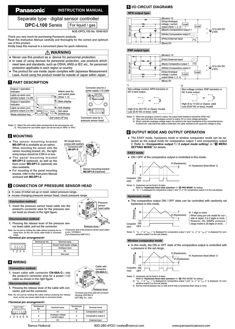
  9. Panasonic KT4R Use and care manual

Panasonic KT4R Use and care manual

COMMUNICATION INSTRUCTION MANUAL Temperature Controller KT4R
No. KT4RCE1 2015.06
This manual contains instructions for communication functions of the KT4R.
To prevent accidents arising from the misuse of this controller, please ensure the operator receives this manual.
For model number and basic operation, please read the User’s Manual for the KT4R.
Warning
Turn the power supply to the instrument off before wiring or checking.
Working on or touching the terminal with the power switched on may result in severe injury or death
due to electric shock.
1. System Configuration
1.1 When Using Communication Converter (sold separately)
(Fig. 1.1-1)
1.2 When Using a PLC
(Fig. 1.2-1)
Communication converter
(sold separately)
RS-232C RS-485
No. 1
No. 2
No. 31
KT4R
Host computer
No. 1
No. 2
No.
31
KT4R
PLC
RS
-
485
Phone: 800.894.0412 - Fax: 888.723.4773 - Web: www.clrwtr.com - Email: [email protected]
2. Wiring
2.1 When Using Communication Converter (sold separately)
(Fig. 2.1-1)
2.2 When Using a PLC (RS-485)
(Fig. 2.2-1)
FG
FG
FG
⑯YA(-)
⑰YB(+)
⑱SG
⑯YA(-)
⑰YB(+)
⑱SG
⑯YA(-)
⑰YB(+)
⑱SG
(-)
(+)
PLC KT4R
Shield wire
Shield wire
Shield wire
RXD
TXD
DCD
DTR
DSR
RTS
CTS
2
3
5
1
4
6
7
8
GND
RI 9
FG
FG
FG
FG
YA(-)
YB(+)
COM
RX
TX
COM
⑯YA(-)
⑰YB(+)
⑱SG
⑯YA(-)
⑰YB(+)
⑱SG
⑯YA(-)
⑰YB(+)
⑱SG
KT4R
Shield wire Shield wire
Shield wire
Shield wire
D-sub 9-pin connector
RS-232C RS-485
Host computer Communication converter
(sold separately)
Phone: 800.894.0412 - Fax: 888.723.4773 - Web: www.clrwtr.com - Email: [email protected]
Shield wire
Connect only one end of the shield wire to the FG terminal so that current cannot flow to the shield wire.
If both ends of the shield wire are connected to the FG terminal, the circuit will be closed between the
shield wire and the ground. As a result, current will run through the shield wire, and this may cause noise.
Be sure to ground the FG terminal.
Recommended cable: OTSC-VB 2PX0.5SQ (made by Onamba Co., Ltd.) or equivalent (Use a twisted pair
cable).
Terminator (Terminal resistor)
The terminator is mounted at the end of the wire when connecting a personal computer to multiple peripheral
devices. The terminator prevents signal reflection and disturbance.
It is not necessary to connect a terminator to the communication line because the KT4R has built-in pull-up
and pull-down resistors.
For communication between the PLC and KT4R, terminators are not necessary. However, to reduce the risk
of reflection, connect a terminator to the PLC side.
Use a terminator of 120 or more.
Phone: 800.894.0412 - Fax: 888.723.4773 - Web: www.clrwtr.com - Email: [email protected]
3. Setting Communication Parameters
Set communication parameters in Engineering mode.
To enter Engineering mode, press and hold the and keys (in thatorder) for approx. 3secondsin RUNmode.
Use the or key for settings (or selections).
To register the set data, use the key.
The following outlines the procedure for communication parameter setting.
RUN mode
PV/SV Display
+ (3 sec)
Engineering mode
Set value lock
(Several times)
Communication protocol
Characters,
Factory Default Setting Item, Function, Setting Range
Communication protocol
• Selects the communication protocol.
• Selection item:
MEWTOCOL
Modbus ASCII
Modbus RTU
Modbus ASCII (KT4 command allocation)
Modbus RTU (KT4 command allocation)
Instrument number
• Sets the instrument number.
The instrument numbers should be set one by one when multiple instruments are
connected in Serial communication, otherwise communication is not possible.
• Setting range: 1 to 95 [Do not use 0 (zero) – 0 cannot be used as an instrument number.]
Communication speed
• Selects a communication speed equal to that of the host computer.
• Selection item:
9600 bps
19200 bps
38400 bps
Data bit/Parity
• Selects the data bit and parity.
• Selection item:
8 bits/No parity
7 bits/No parity
8 bits/Even
7 bits/Even
8 bits/Odd
7 bits/Odd
Phone: 800.894.0412 - Fax: 888.723.4773 - Web: www.clrwtr.com - Email: [email protected]
Characters,
Factory Default Setting Item, Function, Setting Range
Stop bit
• Selects the stop bit.
• Selection item:
1 bit
2 bits
Response delay time
• Response from the controller can be delayed after receiving command from the host
computer.
• Setting range: 0 to 1000 ms
(Many times)
RUN mode
PV/SV Display
Now, settings are complete.
Phone: 800.894.0412 - Fax: 888.723.4773 - Web: www.clrwtr.com - Email: [email protected]
4. MEWTOCOL
4.1 Communication Procedure
Communication starts with command transmission from the host computer, and ends with the response
of the KT4R (controller).
4.1.1 Response with Data
When the host computer sends the Read command,
the KT4R responds with the corresponding set value
or current status.
(Fig. 4.1.1-1)
4.1.2 Acknowledgement
When the host computer sends the Write command,
the KT4R responds by sending acknowledgement
after processing is terminated.
(Fig. 4.1.2-1)
4.1.3 Negative Acknowledgement
When the host computer sends a non-existent
command or value out of the setting range, the KT4R
returns a negative acknowledgement.
(Fig. 4.1.3-1)
4.2 Communication Timing of the RS-485
Master side (Take note while programming)
When the master starts transmission through the RS-485 communication line, the master is arranged so
as to provide an idle status (mark status) transmission period of 1 character or more before sending the
command to ensure synchronization on the receiving side.
Set the program so that the master can disconnect the transmitter from the communication line within a
1 character transmission period after sending the command in preparation for reception of the response
from the slave.
To avoid collision of transmissions between the master and the slave, send the next command after
carefully checking that the master has received the response.
If a response to the command is not returned due to communication errors, set the Retry Processing to
send the command again. (It is recommended to execute Retry twice or more.)
Slave side
When the slave starts transmission through the RS-485 communication line, the slave is arranged so as
to provide an idle status (mark status) transmission period of 1 ms or more (*) before sending a response
to ensure synchronization on the receiving side.
The slave is arranged so as to disconnect the transmitter from the communication line within a 1 character
transmission period, after sending the response.
(*) Can be set in [Response delay time (p.5.)] within a range of 0 to 1000 ms.
Read command
Response data
Host computer KT4R
Write command
Acknowledgement
Host computer KT4R
Non-existent command or
data out of the setting range
Negative acknowledgement
Host computer KT4R
Phone: 800.894.0412 - Fax: 888.723.4773 - Web: www.clrwtr.com - Email: [email protected]
4.3 Data Format
Data format is shown below.
Start bit B1 B2 B3 B4 B5 B6 B7 B8 Parity Stop bit
Start bit 1 bit
Data bit 7 bits/8 bits
Parity Even parity/Odd parity/No parity
Stop bit 1 bit/2 bits
4.4 Command Structure
All commands are composed of ASCII, and have the following structures.
Numerals written above the command represent the number of characters.
4.4.1 RCP Command Structure
Contact Area Read
Reads ON/OFF status of multiple contacts (R only).
8 points to 1 command can be specified.
Command
1 2 1 3 1 1 4
% # RCP R
25H Address
(Decimal) 23H 52H 43H 50H
Number of
contacts n
(1 to 8) 52H Contact No.
(1)
101100103102101160
1 4 2 1
R CR
52H Contact No.
(n) BCC 0DH
103102101160161160
Acknowledgement
1 2 1 2 1 1 2 1
% $ RC CR
25H Address
(Decimal) 24H 52H 43H Contact data
(1) Contact data
(n) BCC 0DH
101100161160
Negative acknowledgement
1 2 1 2 2 1
% ! CR
25H Address
(Decimal) 21H Error code
(Hexadecimal) BCC 0DH
101100161160161160
Phone: 800.894.0412 - Fax: 888.723.4773 - Web: www.clrwtr.com - Email: [email protected]
4.4.2 WCP Command Structure
Contact Area Write
Multiple contacts (R only) are set to ON/OFF.
8 points to 1 command can be specified.
Command
1 2 1 3 1 1 4 1
% # WCP R
25H Address
(Decimal) 23H 57H 43H 50H
Number of
contacts n
(1 to 8) 52H Contact No.
(1) Contact data
(1)
101100103102101160
1 4 1 2 1
R CR
52H Contact No.
(n) Contact data
(n) BCC 0DH
103102101160161160
Acknowledgement
1 2 1 2 2 1 ・・・Number of characters
% $ WC CR
25H Address
(Decimal) 24H 57H 43H BCC 0DH
101100161160
Negative acknowledgement
1 2 1 2 2 1 ・・・Number of characters
% ! CR
25H Address
(Decimal) 21H Error code
(Hexadecimal) BCC 0DH
101100161160161160
Phone: 800.894.0412 - Fax: 888.723.4773 - Web: www.clrwtr.com - Email: [email protected]
4.4.3 RD Command Structure
Data Area Read
Reads contents of data area (DT area only).
16 pieces of data to 1 command can be specified.
Command
1 2 1 2 1 5
% # RD D
25H Address
(Decimal) 23H 52H 44H 44H Starting data No.
( Decimal)
101100104103102101100
5 2 1
CR
Ending data No.
(Decimal) BCC 0DH
104103102101100161160
Acknowledgement
1 2 1 2 4 4
% $ RD
25H Address
(Decimal) 24H 52H 44H Starting data
(Hexadecimal) Ending data
(Hexadecimal)
101100161160163162161160163162
Low High Low High 2 1
CR
BCC 0DH
161160
Negative acknowledgement
1 2 1 2 2 1
% ! CR
25H Address
(Decimal) 21H Error code
(Hexadecimal) BCC 0DH
101100161160161160
Phone: 800.894.0412 - Fax: 888.723.4773 - Web: www.clrwtr.com - Email: [email protected]
4.4.4 WD Command Structure
Data Area Write
Writes data to data area (DT area only).
16 pieces of data to 1 command can be specified.
Command
1 2 1 2 1 5 5
% # WD D
25H Address
(Decimal) 23H 57H 44H 44H Starting data No.
(Decimal) Ending data No.
(Decimal)
101100104103102101100104103102101100
4 4 2 1
CR
Write Starting data
(Hexadecimal) Write Ending data
(Hexadecimal) BCC 0DH
161160163162161160163162161160
Low High Low High
Acknowledgement
1 2 1 2 2 1
% $ WD CR
25H Address
(Decimal) 24H 57H 44H BCC 0DH
101100161160
Negative acknowledgement
1 2 1 2 2 1
% ! CR
25H Address
(Decimal) 21H Error code
(Hexadecimal) BCC 0DH
101100161160161160
Phone: 800.894.0412 - Fax: 888.723.4773 - Web: www.clrwtr.com - Email: [email protected]
4.4.5 MC Command Structure
Monitor Contact Register/Reset
Registers contact (R only) to be monitored.
Up to 16 contacts can be registered.
Command
1 2 1 2 1 4
% # MC R
25H Address
(Decimal) 23H 4DH 43H 52H Contact No.
(1)
101100103102101160
1 4 2 1
R CR
52H Contact No.
(n) BCC 0DH
103102101160161160
Reset1 2 1 2 5 2 1
% # MC FFFFF CR
25H Address
(Decimal) 23H 4DH 43H 46H 46H 46H 46H 46H BCC 0DH
101100161160
Acknowledgement
1 2 1 2 2 1
% $ MC CR
25H Address
(Decimal) 24H 4DH 43H BCC 0DH
101100161160
Negative acknowledgement
1 2 1 2 2 1
% ! CR
25H Address
(Decimal) 21H Error code
(Hexadecimal) BCC 0DH
101100161160161160
Phone: 800.894.0412 - Fax: 888.723.4773 - Web: www.clrwtr.com - Email: [email protected]
4.4.6 MD Command Structure
Monitor Data Register/Reset
Registers data (DT only) to be monitored.
Up to 16 pieces of data can be registered.
Command
1 2 1 2 1 5
% # MD D
25H Address
(Decimal) 23H 4DH 44H 44H Specified data No.
(1)( Decimal)
101100104103102101100
1 5 2 1
D CR
44H Specified data No.
(n)(Decimal) BCC 0DH
104103102101100161160
Reset1 2 1 2 6 2 1
% # MD FFFFFF CR
25H Address
(Decimal) 23H 4DH 44H 46H 46H 46H 46H 46H 46H BCC 0DH
101100161160
Acknowledgement
1 2 1 2 2 1
% $ MD CR
25H Address
(Decimal) 24H 4DH 44H BCC 0DH
101100161160
Negative acknowledgement
1 2 1 2 2 1
% ! CR
25H Address
(Decimal) 21H Error code
(Hexadecimal) BCC 0DH
101100161160161160
Phone: 800.894.0412 - Fax: 888.723.4773 - Web: www.clrwtr.com - Email: [email protected]
4.4.7 MG Command Structure
Monitor Data Execute
Monitors registered contacts or data.
Command
1 2 1 2 2 1
% # MG CR
25H Address
(Decimal) 23H 4DH 47H BCC 0DH
101100161160
Acknowledgement
1 2 1 2 1 2 2
% $ MG
25H Address
(Decimal) 24H 4DH 47H Pace
Counter
Contact data:
Number of
characters (mx
2)
Contact data
(1)
101100161160161160
2 2 4 4 2 1
CR
Contact data
(m)
Data:
Number of
characters (nx4)
Data
(1) Data
(n) BCC 0DH
161160161160161160163162161160163162161160
Low High Low High
Negative acknowledgement
1 2 1 2 2 1
% ! CR
25H Address
(Decimal) 21H Error code
(Hexadecimal) BCC 0DH
101100161160161160
Notice
To execute Monitor data with the MG command, register the Monitor contact and Monitor data using
the MC command (Monitor contact register) and the MD command (Monitor data register)
beforehand.
If Monitor data is not registered and is executed with the MG command, it will result in negative
acknowledgement, and Error code 62H will be returned.
Phone: 800.894.0412 - Fax: 888.723.4773 - Web: www.clrwtr.com - Email: [email protected]
Header: Represents the beginning of the command and the response.
ASCII % (25H) is used.
Address (Instrument number): Numbers by which the master discerns each slave.
Instrument numbers 1 to 95 (2-digit decimal) and Global addresses EE and FF are used.
By using the Global address, the same command can be sent to all connected slaves.
For the Global address EE, EE is appended to the address of response command.
For the Global address FF, a response is not returned.
Command: Codes to discern message are described below.
ASCII Name Description
#(23H) Command Represents command message.
$(24H) Response (normal) Represents normal response message.
!(21H) Response (error) Represents response message when an error has
occurred.
Command code: 4 types of command code are listed below.
Command
Code Contents Description
RCP Contact Area Read
(multiple points) Reads ON/OFF status of multiple contacts
(R only).
Up to 8 points to 1 command can be
specified.
WCP Contact Area Write
(multiple points) Multiple contacts (R only) are set to
ON/OFF.
Up to 8 points to 1 command can be
specified.
RD Data Area Read Reads the contents of data area (DT area
only).
Up to 16 pieces of data to 1 command can
be specified.
WD Data Area Write Writes data to data area (DT area only).
Up to 16 pieces of data to 1 command can
be specified.
MC Monitor Contact
Register/Reset Registers contact (R only) to be monitored.
Up to 16 contacts can be registered.
MD Monitor Data Register/Reset Registers data (DT only) to be monitored.
Up to 16 pieces of data can be registered.
MG Monitor Data Execute Monitors registered contact or data.
Data code: Specifies data register DT.
ASCII D (44H) is used.
Phone: 800.894.0412 - Fax: 888.723.4773 - Web: www.clrwtr.com - Email: [email protected]
Data: Composed of 5-digit decimal, 4-digit hexadecimal, or ‘3-digit decimal+1-digit hexadecimal’,
expressed using ASCII.
Negative numbers are represented in 2's complement.
Decimal data
(e.g.) Starting data No. of Data area Read (RD) command
Starting data No.
(Decimal)
104103102101100
0 0 1 0 7 107 (Actual data)
Hexadecimal data
(e.g.) Starting data of Data area Read (RD) acknowledgement
Starting data
(Hexadecimal)
161160163162
Low High
1 0 2 7 2710H (Actual data)
Decimal + Hexadecimal data
For the Contact No. of the contact (R), the least significant digit is expressed
in hexadecimal, and other higher digits are expressed in decimal.
(e.g.) Specifying Contact No. of Contact area Read (RCP) command
R
52H Contact No.
(1)
103102101160
0 0 2 F R002F (Actual designation)
BCC: BCC (Block check code) is a code to detect transmission errors.
Using horizontal parity, XOR is calculated from the header through the last text
character, and is expressed in ASCII.
Terminator: Represents the end of command.
ASCII CR(0DH) is used.
Error code: Represents an error type using ASCII.
Error code Description
40H BCC error
41H Format error, #, non-existent data item
42H Not-support command
43H Procedure error, Delimiter (&) error
60H Any data code except D, Any contact except R
61H Data error (data item is not correct)
62H Registration error
63H Mode error
Phone: 800.894.0412 - Fax: 888.723.4773 - Web: www.clrwtr.com - Email: [email protected]
4.5 Example of BCC (Block Check Code) Calculation
(e.g.) % 01 # RD D 00101 00107
% 25H
0 30H
1 31H
# 23H
R 52H
D 44H
D 44H
0 30H
0 30H
1 31H
0 30H
1 31H
0 30H
0 30H
1 31H
0 30H
7 37H
53H (Exclusive OR)
Converts to ASCII. BCC (H) = 5 (35H), BCC (L) = 3 (33H)
% 01 # RD D 00101 00107 53 CR
Phone: 800.894.0412 - Fax: 888.723.4773 - Web: www.clrwtr.com - Email: [email protected]
4.6 Command Example
Numerals written above the command represent the number of characters.
4.6.1 Read (Address 1, PV, OUT1 MV, OUT2 MV, Current SV)
•Read command from the master
1 2 1 2 1 5
% Address # RD D Starting data No.
25H 30H 31H 23H 52H 44H 44H 30H 30H 33H 35H 36H
01 003565 2 1
Ending data No. BCC CR
30H 30H 33H 35H 39H 35H 41H 0DH
00359 5A
•A response from the slave in normal status [PV: 600 (0258H), OUT1 MV: 30.0% (012CH),
OUT2 MV: 0.0% (0000H), Current SV: 600 (0258H)]
1 2 1 2 4 4
% Address $ RD Starting data Starting data +1
25H 30H 31H 24H 52H 44H 35H 38H 30H 32H 32H 43H 30H 31H
01 5802 2C01
4 4 2 1
Starting data +2 Ending data BCC CR
30H 30H 30H 30H 35H 38H 30H 32H 36H 36H 0DH
0000 5802 66
4.6.2 Write (Address 1, Input type, Scaling high limit, Scaling low limit, Decimal point place)
•Write command from the master [Input type: 4 to 20 mADC (001EH), Scaling high limit: 1000 (03E8H),
Scaling low limit: 0 (0000H), Decimal point place: 1 digit after decimal point (0001H)]
1 2 1 2 1 5 5
% Address # WD D Starting data No. Ending data No.
25H 30H 31H 23H 57H 44H 44H 30H 30H 31H 30H 32H 30H 30H 31H 30H 35H
01 00102 00105
4 4 2 1
Write
Starting data Write
Starting data + 1 Write
Starting data + 2 Write
Ending data BCC CR
31H 45H 30H 30H 45H 38H 30H 33H 30H 30H 30H 30H 30H 31H 30H 30H 35H 43H 0DH
1 E 0 0 E 8 0 3 0 0 0 0 0 1 0 0 5 C
• Aresponse from the slave in normal status
1 2 1 2 2 1
% Address $ WD BCC CR
25H 30H 31H 24H 57H 44H 31H 33H 0DH
0 1 1 3
Phone: 800.894.0412 - Fax: 888.723.4773 - Web: www.clrwtr.com - Email: [email protected]
Program control RUN
1:00 2:00
200
0
0:30 1:00 2:00
300
4.6.3 Write (Address 1, Program pattern data)
Program pattern setting example
Step 1 2 3 4 5
SV ( ) 200 200 300 300 0
Time 1:00 2:00 0:30 1:00 2:00
Wait value ( ) 10 0 10 0 0
(Fig. 4.6.3-1)
When writing the above program pattern, command data section converts to the following.
Data: Data in the following table is converted to Hexadecimal.
MEWTOCOL Data Item Data Data (Converted to Hexadecimal)
DT01000 1000H Step 1 SV 200 00C8H
DT01001 1001H Step 1 time 60 minutes (1:00) 003CH
DT01002 1002H Step 1 wait value 10 000AH
DT01003 1003H Step 2 SV 200 00C8H
DT01004 1004H Step 2 time 120 minutes (2:00) 0078H
DT01005 1005H Step 2 wait value 0 0000H
DT01006 1006H Step 3 SV 300 012CH
DT01007 1007H Step 3 time 30 minutes (0:30) 001EH
DT01008 1008H Step 3 wait value 10 000AH
DT01009 1009H Step 4 SV 300 012CH
DT01010 100AH Step 4 time 60 minutes (1:00) 003CH
DT01011 100BH Step 4 wait value 0 0000H
DT01012 100CH Step 5 SV 0 0000H
DT01013 100DH Step 5 time 120 minutes (2:00) 0078H
DT01014 100EH Step 5 wait value 0 0000H
•Write command from the master (When writing the above program pattern data)
1 2 1 2 1 5 5
% Address # WD D Starting data No. Ending data No.
25H 30H 31H 23H 57H 44H 44H 30H 31H 30H 30H 30H 30H 31H 30H 31H 34H
01 01000 01014
4 4 2 1
Write
Starting data Write
Starting data + 1 Write
Starting data + 2 Write
Ending data BCC CR
43H 38H 30H 30H 33H 43H 30H 30H 30H 41H 30H 30H 30H 30H 30H 30H 32H 31H 0DH
C 8 0 0 3 C 0 0 0 A 0 0 0 0 0 0 2 1
•Response from the slave in normal status
1 2 1 2 2 1
% Address $ WD BCC CR
25H 30H 31H 24H 57H 44H 31H 33H 0DH
0 1 1 3
Phone: 800.894.0412 - Fax: 888.723.4773 - Web: www.clrwtr.com - Email: [email protected]
4.6.4 Read (Address 1, program pattern data)
•Read command from the master (when reading the previous program pattern data)
1 2 1 2 1 5
% Address # RD D Starting data No.
25H 30H 31H 23H 52H 44H 44H 30H 31H 30H 30H 30H
01 010005 2 1
Ending data No. BCC CR
30H 31H 30H 31H 34H 35H 30H 0DH
01014 50
•Response from the slave in normal status
1 2 1 2 4 4
% Address $ RD Starting data Starting data + 1
25H 30H 31H 24H 52H 44H 43H 38H 30H 30H 33H 43H 30H 30H
0 1 C 8 0 0 3 C 0 0
4 4 2 1
Starting data + 2 Ending data BCC CR
30H 41H 30H 30H 30H 30H 30H 30H 36H 32H 0DH
0 A 0 0 0 0 0 0 6 2
Response data section converts to the following.
MEWTOCOL Data Item Data Data (Converted to Hexadecimal)
DT01000 1000H Step 1 SV 200 00C8H
DT01001 1001H Step 1 time 60 minutes (1:00) 003CH
DT01002 1002H Step 1 wait value 10 000AH
DT01003 1003H Step 2 SV 200 00C8H
DT01004 1004H Step 2 time 120 minutes (2:00) 0078H
DT01005 1005H Step 2 wait value 0 0000H
DT01006 1006H Step 3 SV 300 012CH
DT01007 1007H Step 3 time 30 minutes (0:30) 001EH
DT01008 1008H Step 3 wait value 10 000AH
DT01009 1009H Step 4 SV 300 012CH
DT01010 100AH Step 4 time 60 minutes (1:00) 003CH
DT01011 100BH Step 4 wait value 0 0000H
DT01012 100CH Step 5 SV 0 0000H
DT01013 100DH Step 5 time 120 minutes (2:00) 0078H
DT01014 100EH Step 5 wait value 0 0000H
Phone: 800.894.0412 - Fax: 888.723.4773 - Web: www.clrwtr.com - Email: [email protected]
5. Modbus Protocol
5.1 Communication Procedure
Communication starts with command transmission from the host computer (master), and ends with the
response of the KT4R (slave).
5.1.1 Response with Data
When the master sends the Read command, the slave
responds with the corresponding set value or current
status.
(Fig. 5.1.1-1)
5.1.2 Acknowledgement
When the master sends the Write command, the
slave responds by sending acknowledgement
after processing is terminated.
(Fig. 5.1.2-1)
5.1.3 Negative Acknowledgement
When the master sends a non-existent command or
value out of the setting range, the slave returns
negative acknowledgement.
(Fig. 5.1.3-1)
5.1.4 No Response
The slave will not respond to the master in the following
cases:
• Broadcast address
• Communication error (framing error, parity error)
• LRC discrepancy (Modbus ASCII mode)
• CRC-16 discrepancy (Modbus RTU mode)
(Fig. 5.1.4-1)
Read command
Response data
Master Slave
Write command
Acknowledgement
Master Slave
Non-existent command or
data out of the setting range
Negative acknowledgement
Master Slave
Broadcast address,
Communication error
(framing error, parity error)
LRC discrepancy,
CRC-16 discrepancy
No response
Master Slave
Phone: 800.894.0412 - Fax: 888.723.4773 - Web: www.clrwtr.com - Email: [email protected]

Other manuals for KT4R

1

Other Panasonic Controllers manuals

Panasonic EF-S1C User manual

Panasonic

Panasonic EF-S1C User manual

Panasonic MINAS S-series User manual

Panasonic

Panasonic MINAS S-series User manual

Panasonic SQ4-C11 User manual

Panasonic

Panasonic SQ4-C11 User manual

Panasonic AWLK30 - LENS CONTROLLER User manual

Panasonic

Panasonic AWLK30 - LENS CONTROLLER User manual

Panasonic FP-X0 L14R User manual

Panasonic

Panasonic FP-X0 L14R User manual

Panasonic FP-I4C User manual

Panasonic

Panasonic FP-I4C User manual

Panasonic DPC-100 Series User manual

Panasonic

Panasonic DPC-100 Series User manual

Panasonic FP-I4C User manual

Panasonic

Panasonic FP-I4C User manual

Panasonic CZ-64ESMC3 User manual

Panasonic

Panasonic CZ-64ESMC3 User manual

Panasonic AG-A850 User manual

Panasonic

Panasonic AG-A850 User manual

Panasonic WVCU950 - CONTROLLER - ADDENDUM User manual

Panasonic

Panasonic WVCU950 - CONTROLLER - ADDENDUM User manual

Panasonic MGSD Installation guide

Panasonic

Panasonic MGSD Installation guide

Panasonic FP7 Series User manual

Panasonic

Panasonic FP7 Series User manual

Panasonic FP7 Series User manual

Panasonic

Panasonic FP7 Series User manual

Panasonic Minas A4 Series User manual

Panasonic

Panasonic Minas A4 Series User manual

Panasonic FP-M Hardware User manual

Panasonic

Panasonic FP-M Hardware User manual
Panasonic CZ-256ESMC2U User manual

Panasonic

Panasonic CZ-256ESMC2U User manual

Panasonic FP7 Series Installation manual

Panasonic

Panasonic FP7 Series Installation manual

Panasonic CZ-RELC2 User manual

Panasonic

Panasonic CZ-RELC2 User manual

Panasonic FP7 Series User manual

Panasonic

Panasonic FP7 Series User manual

Panasonic AFPXHEAD4 User manual

Panasonic

Panasonic AFPXHEAD4 User manual

Panasonic PAW-HPM 1 User manual

Panasonic

Panasonic PAW-HPM 1 User manual

Panasonic FV-SW20VEC1 User manual

Panasonic

Panasonic FV-SW20VEC1 User manual

Panasonic FP-XH Series User manual

Panasonic

Panasonic FP-XH Series User manual

Popular Controllers manuals by other brands

Master WiSlide 750 KG User and installation manual

Master

Master WiSlide 750 KG User and installation manual

Adaptec ICP 5045BL install guide

Adaptec

Adaptec ICP 5045BL install guide

SWARCO McCain Omni eX quick start guide

SWARCO

SWARCO McCain Omni eX quick start guide

Isimet DLA Series Style 2 Installation, Operations, Start-up and Maintenance Instructions

Isimet

Isimet DLA Series Style 2 Installation, Operations, Start-up and Maintenance Instructions

3M MicroTouch EX113 reference guide

3M

3M MicroTouch EX113 reference guide

S&C PMH Instructions for operation

S&C

S&C PMH Instructions for operation

Fuelab 72001 Operating and installation instructions

Fuelab

Fuelab 72001 Operating and installation instructions

Rotork Fairchild PAX1 user manual

Rotork Fairchild

Rotork Fairchild PAX1 user manual

LMI LIQUITRON 7000 Series Installation & operation manual

LMI

LMI LIQUITRON 7000 Series Installation & operation manual

Emerson Fisher L2e instruction manual

Emerson

Emerson Fisher L2e instruction manual

Holtek HT46R62 Handbook

Holtek

Holtek HT46R62 Handbook

MidNite Solar Classic 150 owner's manual

MidNite Solar

MidNite Solar Classic 150 owner's manual

ZIMO MX31FU instruction manual

ZIMO

ZIMO MX31FU instruction manual

Prolon C1050 Series Hardware guide

Prolon

Prolon C1050 Series Hardware guide

elero InDrive M30/1.6 RH Operating and assembly instructions

elero

elero InDrive M30/1.6 RH Operating and assembly instructions

Extron electronics MLC 206 Backlight Replacement Guide

Extron electronics

Extron electronics MLC 206 Backlight Replacement Guide

EisSound KBSOUND 60201 user manual

EisSound

EisSound KBSOUND 60201 user manual

Newport Electronics INFINITY Series manual

Newport Electronics

Newport Electronics INFINITY Series manual

manuals.online logo
manuals.online logoBrands
  • About & Mission
  • Contact us
  • Privacy Policy
  • Terms and Conditions

Copyright 2025 Manuals.Online. All Rights Reserved.