Table of Contents
Page Page
1. Safety Precautions............................................................5
1.1. For Service Technicians.......................................................5
1.2. Insulation Resistance Test (by Insulation resistance
tester).............................................................................................5
1.3. Power Caution....................................................................... 5
2. Warning..............................................................................6
2.1. Battery Caution......................................................................6
2.2. About Lead Free Solder (PbF: Pb free)............................... 6
2.2.1. Suggested Pbf Solder.......................................................6
2.3. Discarding of P.C. Board......................................................7
2.4. Note For Repairing................................................................7
2.5. Disposal of old Equipment...................................................7
3. Specifications....................................................................8
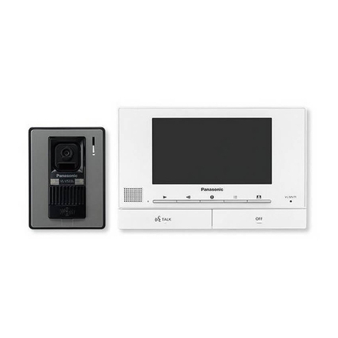
3.1. Main monitor station (VL-MV74)...........................................8
3.2. Door phone (VL-V524L).........................................................8
4. Technical Descriptions.....................................................9
4.1. Block Diagram....................................................................... 9
4.2. IC Operation.........................................................................11
4.2.1. Monitor Station Section...................................................11
4.2.2. Door Station Section.......................................................15
5. Location of Controls and Components........................ 17
6. Installation Instructions................................................. 18
7. Operating Instructions................................................... 19
8. Service Mode...................................................................20
8.1. Things to do after replacing IC...........................................20
8.1.1. Main Monitor Station.......................................................20
9. Troubleshooting Guide.................................................. 21
9.1. Operation Check of the Door Station................................ 21
9.2. Operation Check of the Main Monitor Station.................. 25
9.2.1. Defect of Communication Between the Main Monitor
Station and Extension Monitor..................................................26
9.2.2. Defect of the Extension Monitor Video Recording..........27
9.2.3. Defect of the Main Monitor Station Power Supply.......... 28
9.2.4. Defect of the Main Monitor Station Video Recording......32
9.2.5. Defect of the Communication Between the Main Monitor
Station and the Door Station.....................................................33
9.2.6. Defect of the Communication Between the Extention
Monitor Station and the Door Station........................................34
9.2.7. Defect of the Key board unit........................................... 35
9.3. Signal Route.........................................................................36
10. Disassembly and Assembly Instructions...................42
10.1. Main Monitor Station.........................................................42
10.1.1. How to Remove the AC Cord [No.1].............................42
10.1.2. How to Remove the Cabinet Cover [No.2]....................42
10.1.3. How to Remove the Main Board, Speaker and LCD [No.
3]...............................................................................................43
10.1.4. How to Remove the Power board, Key board [No.4]....44
10.2. Door Station.......................................................................45
10.2.1. How to Remove the Front Panal [No.1]........................45
10.2.2. How to Remove the Door Station [No.2].......................46
10.2.3. How to Remove the Main Board and Camera Unit [No.3]
..................................................................................................47
10.2.4. How to Remove the Mic Board and Speaker [No.4].....48
10.2.5. Installation of the lead wires..........................................50
10.2.6. Item to be checked after completion of assembly
(camera lens angle adjustment)................................................50
11. Measurements and Adjustments.................................51
11.1. Main Monitor Station.........................................................51
11.1.1. Main Board....................................................................51
11.1.2. Factory Mode................................................................53
11.2. Door Station.......................................................................56
12. Miscellaneous............................................................... 57
12.1. How to Replace the Flat Package IC................................57
12.1.1. Preparation................................................................... 57
12.1.2. Flat Package IC Removal Procedure............................57
12.1.3. Flat Package IC Installation Procedure.........................58
12.1.4. Bridge Modification Procedure......................................58
13. Schematic Diagram.......................................................59
13.1. Main Monitor Station.........................................................60
13.1.1. Main Board (1) / External I/F.........................................60
13.1.2. Main Board (2) / BBIC...................................................61
13.1.3. Main Board (3) / DPJP3_KEY.......................................62
13.1.4. Main Board (4) / LCD....................................................63
13.1.5. Main Board (5) / External I/F_Electric lock....................64
13.1.6. Main Board (6) / DCDC.................................................65
13.1.7. Main Board (7) / AM communication_base unit............66
13.1.8. Main Board (8) / AM communication_add base unit.....67
13.1.9. Main Board (9) / KEY....................................................68
13.1.10. Power Board...............................................................69
13.2. Door Station.......................................................................70
13.2.1. Main Board....................................................................70
13.2.2. MIC Board.....................................................................71
14. Printed Circuit Board....................................................72
14.1. Main Monitor Station.........................................................72
14.1.1. Main Board (Component View).....................................72
14.1.2. Main Board (Bottom View)............................................73
14.1.3. Key Board.....................................................................74
14.1.4. Power Board.................................................................75
14.2. Door Station Board............................................................76

