manuals.online logo
Brands
  1. Home
  2. •
  3. Brands
  4. •
  5. Panasonic
  6. •
  7. Intercom System
  8. •
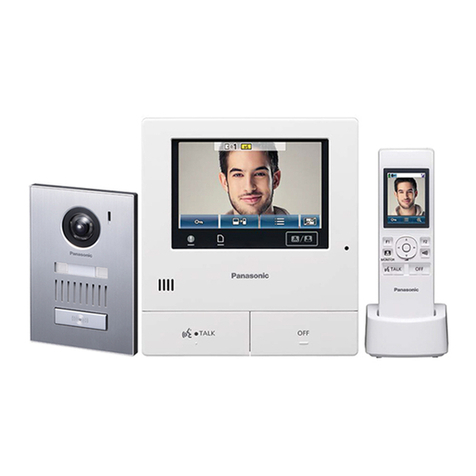
  9. Panasonic VL-SWD501EX User manual

Panasonic VL-SWD501EX User manual

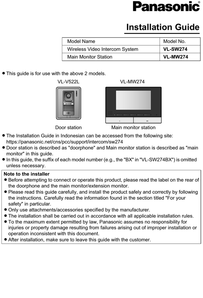
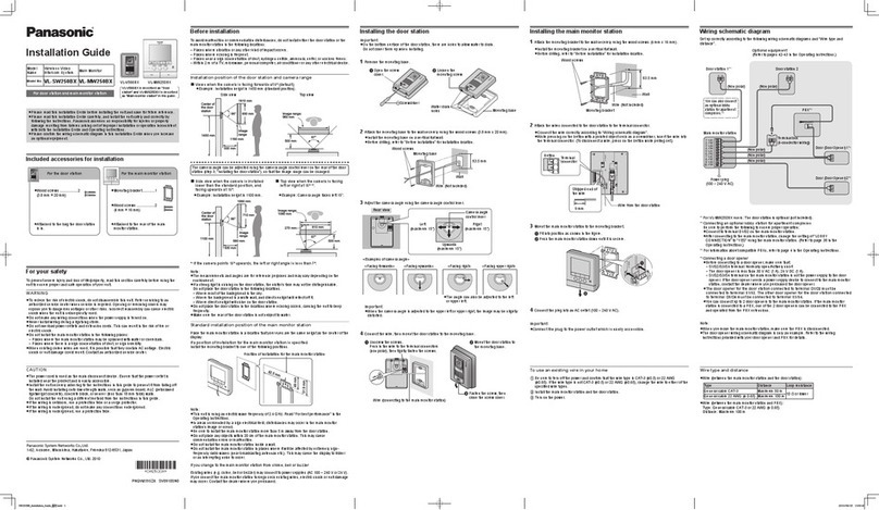
Installation Guide
Note to the installer
■ Beforeattemptingtoconnectoroperatethisproduct,pleasereadthelabelontherearof
themainmonitor.
■
Pleasereadthis
guide
carefully,andinstalltheproductsafelyandcorrectlybyfollowing
theinstructions.Carefullyreadtheinformationfoundinthesectiontitled"Foryoursafety"
inparticular.
■
Onlyuseattachments/accessoriesspecifiedbythemanufacturer.
■
Theinstallationshallbecarriedoutinaccordancewithallapplicableinstallationrules.
■
Panasonicassumesnoresponsibilityforinjuriesorpropertydamageresultingfromfailures
arisingoutofimproperinstallationoroperationinconsistentwiththisguide.Additionally,
anyresultingmalfunctionwillnotbecoveredunderthewarranty.
■ Afterinstallation,makesuretoleavethisguidewiththecustomer.
For the Installation of door station
and main monitor station
•VL-V554EXisasurfacemounttype,VL-V554UEX
isaushmounttype.
For your safety
Topreventsevereinjuryandlossoflife/property,readthissectioncarefullybeforeusingthe
producttoensureproperandsafeoperationofyourproduct.
WARNING
Preventingre,electricshockandshortcircuits
● Leaveinstallationworktothedealer.
Installationworkrequirestechniqueandexperiences.Failuretoobservethismay
causere,electricshock,injury,ordamagetotheproduct.Consultthedealer.
● Electricalconnectionworkshouldbeperformedbycertiedpersonnelonly.Certication
isrequiredforperformingelectricalconnectionwork.Consultyourdealer.
● Useonlythespeciedpowersupplyunit.
● Donotattempttodisassemble ormodify thisproduct. Contactan authorisedservice
centreforrepairs.
● Neverinstallwiringduringalightningstorm.
● Donotconnectnon-specieddevices.
● Donotconnectapowercabletoaterminalthatisnotspeciedinthisguide.
● Whenopening holesinwalls for installationor wiring,or whensecuringthepower
cable,makesureyoudonotdamageexistingwiringandductwork.
● Donotmakeanywiringconnectionswhenthepowersupplyisturnedon.
● Donot usethesuppliedpowersupply unitforoutdoor installations(itis forindooruse
only).
● Donotinstallthemainmonitorandpowersupplyunitinthefollowingplaces:
- Placeswherethemainmonitorandpowersupplyunitmaybesplashedwithwateror
chemicals.
- Placeswherethereisahighconcentrationofdust,orhighhumidity.
● Donot performanyactions(such asfabricating,twisting,stretching, bundling,forcibly
bending,damaging,altering,exposingtoheatsources,orplacingheavyobjectsonthe
powercable)thatmaydamage the power cable. Using the product with a damaged
powercablemaycauseelectricshock,shortcircuits,or fire. Contact an authorised
servicecentreforrepairs.
● W hen e xist ing c hime  wire s are u sed,  it is  poss ible  that  they  cont ain AC v olta ge.
Contactanauthorisedservicecentre.
● Donotinstall oruse theproduct inhealth carefacilities ifany regulationspostedin
the area instruct you not to do so. Hospitals or health care facilities may be using
equipmentthatcouldbesensitivetoexternalRF(radiofrequency)energy.
● D o not  ins tall  or us e th is pr oduc t ne ar au toma tic ally  cont rol led d evic es s uch a s
automaticdoorsandfirealarms. Radio waves emitted from this product may cause
suchdevicestomalfunction,resultinginanaccident.
Preventingaccidentsandinjuries
CAUTION
● Ifthewiringisunderground,donotmakeanyconnectionsunderground.
● Ifthewiringisunderground,useaprotectiontube.
● Ifthewiringisoutdoors,useaprotectiontubeorasurgeprotector.
● Install theproduct securely adheringto theinstructionsin thisguide to prevent it from
fallingoffthewall.Avoidinstalling onto low-strength walls, such as gypsum board,ALC
(autoclavedlightweightconcrete),concreteblock,orveneer(lessthan18mmthick)walls.
Preventingelectricshock
Preventinginjury
1-62,4-chome,Minoshima,Hakata-ku,Fukuoka812-8531,Japan
©PanasonicSystemNetworksCo.,Ltd.2013
PNQW3982ZA PC1113MT0
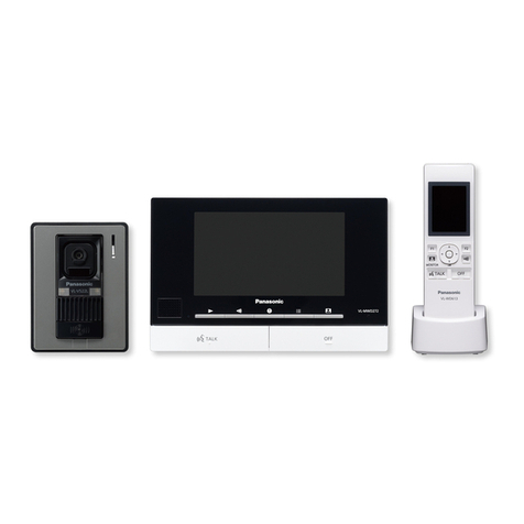
VL-V554EX/
VL-V554UEX
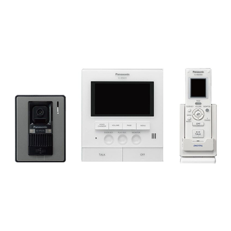
VL-MWD501EX
Doorstation Mainmonitorstation
Doorstationisdescribedas"doorphone"
andMainmonitorstationisdescribedas
"mainmonitor"inthisguide.
ModelNo. VL-SWD501EX
VL-SWD501UEX
Wireless Video Intercom System
Toavoidmalfunctionorcommunicationdisturbances,donotinstallthedoorphoneorthemain
monitorinthefollowinglocations:
- Placeswherevibrationoranyotherkindofimpactoccurs.
- Placeswhereechoingisfrequent.
- Placesnearahighconcentrationofdust,hydrogensulphide,ammonia,sulphur,ornoxious
fumes.
■
For the doorphone
● Ifastronglightisshining onthedoorphone,the visitor’sfacemaynotbedistinguishable.Do
notplacethedoorphoneinthefollowinglocations:
- Wheremostofthebackgroundisthesky.
- Wherethebackgroundisawhitewall,anddirectsunlightwillreectoffit.
- Wheredirectsunlightwillshineonthedoorphone.
● Donot place thedoorphone in locationswhere echoingoccurs, as thiswill cause the
doorphonetobeepfrequently.
● Dustprotection/waterprotectionisIP54.
Onlywheninstallationworkspeciedinthisguideisproperlyperformedandappropriatewater
protectiontreatmentisperformed.
● Makesuretherearofthedoorphoneisnotsubjecttowater.
● Dependingontheinstallationlocation,condensationmayformonthedoorphone’slenscover.
Thismaycauseimagestobecomeobscured.Condensationwilldissipateasthetemperature
rises.
■
For the main monitor
● Installthe main monitoraway fromelectronic appliancessuch asTVs, radios, personal
computers,airconditioners,boilercontrolpanelswithintercom, home security equipment,
wirelessdevices,ordigitalcordlessphones.
● Donotinstallthemainmonitorinplaceswhereitwillbeaffectedbyextremelyhigh-frequency
radio waves (near broadcasting antennasetc.). Thismay cause thedisplay toicker oran
interruptingnoisetooccur.
● Leaveat least 20cm ofspace above,below, andto theleft and rightsides ofthe main
monitor.Donotinstallonawallthatisdeeplyrecessed.
● Donotinstallthemainmonitorinsideawall.
● Besuretoinstallthemainmonitormorethan5mawayfromthedoorphone.
● Theproduct operates inthe frequency rangeof 1.88 GHzto 1.90 GHz,and the RF
transmission power is 250 mW (max.). Refer to the "For bestperformance"section in the
OperatingInstructions.
● Inareassurrounded bya highelectrical eld,disturbances mayoccur inthe mainmonitor’s
imageorsound.
Supplied accessories for installation
■ For the doorphone
(EXonly)
Mounting
base×1
(UEXonly)
Flush
mounting
box×1
Screw×4(Usedwhen
installingthedoorphone)
(EX

:4mmx12mm)
(UEX:4mmx25mm)
Nameplate×2
(incl.1spare) Hexwrench×1
■ For the main monitor

Mounting
bracket×1 Cablebinder×1
■ Power supply unit and related items

Powersupply
unit×1
(PartNo.VL-PS240) Cablebinder×2
Important:
●You will need the following additional items to install and congure the doorphone
and the main monitor.
[Locally procured]
- Screws(formountingbase:×2,formountingbracket:×2):
Preparethescrews( thedrawingontheright)accordingto
thematerial,structure,strengthandotherfactorsofthemounting
areaandthetotalweightofobjectstobemounted.
- Powercables(AC/DCcables),wires(fordoorphoneandotherconnections):
Preparecablesandwiresoftheappropriatespecication.( "Wiretypeandlength")
Note:
● Theillustrationsinthesuppliedmanual(s)mayvaryslightlyfromtheactualproduct.
4mm
Precautions for installation
Wiring schematic diagram
Setupcorrectlyaccordingtothefollowingwiringschematicdiagramand"Wiretypeandlength".
● Forinformation,suchasordernumbers,aboutoptionaldevicesthatcanbeconnectedto,refertothe"Additional/replacementaccessories"sectionintheOperatingInstructions.
ブ
プ
MAIN MONITOR
DOORPHONE 1
DOORPHONE 2
POWER SUPPLY UNIT
220-240VAC
Connectiondeviceforoptionoutput(Acontact)
*1MakesuretoonlyconnectelectricvehiclegatelockstotheS3/S4terminalsofthe
doorphones.
*2MakesuretoonlyconnectelectricdoorlockstotheS1/S2terminalsofthedoorphones.
NP: Non-polarised
Power
supply
Power
supply
Power
supply
Power
supply
12VAC/DC
12VAC/DC
12VAC/DC
12VAC/DC
Electriclock
(Electricvehicle
gatelock)*1
Electriclock
(Electricdoor
lock)*2
Electriclock
(Electricdoor
lock)*2
Electriclock
(Electricvehicle
gatelock)*1
24VDC
Wire type and length
Wiringrun
Wiretype*1
Diameter Length(Max.)
Mainmonitor–
Doorphone A
φ0.65mm 22AWG 100m
φ1.0mm 18AWG 130m
φ0.5mm CAT5 50m
Mainmonitor–
Powersupplyunit B
φ0.65mm 22AWG 10m
φ1.0mm 18AWG 20m
Powersupplyunit–
ACpowersource Cφ1.2mm-φ2.0mm
(17AWG-12AWG) Norequirement
Doorphone–
Electriclock*2 Dφ0.5mm-φ1.2mm
(24AWG-17AWG)
Accordingtospeci-
cationofconnected
device.
Mainmonitor–
Connectiondeviceforoption
output(Acontact)*2
Eφ0.5mm-φ1.2mm
(24AWG-17AWG)
Accordingtospeci-
cationofconnected
device.
*1Type:Single-paircablewithoutersheath(jacket)
Conductor:Coppersolid
*2Whenusinganelectriclockoraconnectiondeviceforoptionoutput(Acontact),selectadevice
thatmeetsthefollowingguidelines:
● Electriclockconnectionterminal(S1/S2,S3/S4):
- N/Odryclosurecontact
- 12VAC/DC,lessthan1A
● Connectiondeviceforoptionoutput(Acontact)terminal(OUT1/OUT2):
- 24VAC/DC,lessthan0.3A(minimumcontact:5VDC1mA)
A D
D
E
B
C
NP
NP
NP
NP
NP
NP
NP
NP
ScrewA
Youcanusethe[Wide/Zoomsettings]settingonthemainmonitortoselecttheareathat
isvisiblewhenavisitorcalls;availablesettingsare[Wide],[Zoom],and[All](entireimage
display).(Defaultsetting:[Wide])
● Thefollowingvaluesareforwhenthedoorphoneisinstalledinthestandardposition(thecentre
of the doorphone’s height isapproximately1,450mm) and at adistance ofapproximately
500mmfromthecameralens.
■ Installation height and area visible by the camera lens
When set to zoom
Displaysaportionofthewideimageat2timesthesize.
● Be cau se a d igit al z oom i s use d, th e im age q uali ty o f zoo m
displayislowerthanthatofwidedisplayorentireimagedisplay.
Imagedisplayedon
mainmonitor:
● You canuse themain monitor’s[Zoom positionsettings] setting toselect thedesiredarea
visiblewhenzooming.
Refertothefollowingandcongurethemainmonitor.
Entire image display
Theareaaboveandbelowthewideimageisvisible.
Important:
● Onthe bottomsurfaceof thedoorphoneandthe mountingbase,there areholestoallow water
todrain.Donotcoverthemupwheninstalling.
● Whenexistingwiring(suchaschimewires)isused:
- ItmaycontainACvoltagethatmaycauseelectricshockand/ordamagetheproduct.
- Neverusethefollowingtypesofwiring.Consultaqualiedtechnician/dealer.
VL-V554EX VL-V554UEX
1 Attachthemountingbasetothewallsecurely.
Mountingbase
(accessory)
Wire(locallyprocured)
Wall
83.5mm
Screws(locallyprocured)×2
● Installthemountingbaseonaverticalatwall.
1 Installtheflushmountingboxinthe
wall.
Flushmountingbox(accessory)
100mm
Knockouthole*1
151mm
37mm
*1Onlyopentheknockoutholesas
requiredforthewiring.
2 Useahexwrench(accessory)toloosenscrewAandremovethefrontpanelofthedoor-
phone.

ScrewA
Frontpanel
2mmhexwrench
(accessory)
3 Connectthewires.
Terminalforthe
mainmonitor
<Rear
view>
Terminalsfortheelectriclocks
● Recommendedtorque:
0.5N·m{5.1kgf·cm}
● Maximumtorque:
0.7N·m{7.1kgf·cm}
3-1Loosenthescrews.
3-2Pushinthewirestotheterminalconnectors(non-polar),thentightenthescrews.
4 Attachthedoorphonetothemounting
base.
Screws(accessory)×4
4 Attachthedoorphonetotheflushmounting
box.

Screws(accessory)×4
5 AttachthenameplatetothedoorphoneandusescrewAtosecurethefrontpanel.
● Writethenameonthenameplateasneeded.
Nameplate
(accessory)
ScrewA ● Recommendedtorque:
0.35N·m{3.6kgf·cm}
Approx.500
Approx.170°
Approx.2,250
Imagerange
Approx.115°
Approx.500
Imagedisplayedon
mainmonitor:
Approx.1,600
Approx.650
Approx.1,450
Upanddown
Leftandright(whenlookingfromabove)
Up Imagerange
Approx.2,050
Approx.500
Centreof
doorphone
Approx.45°
Centre (default)
Approx.45°
Approx.500
Imagerange
Approx.1,650
Down
Approx.45°
Approx.500
Approx.1,400
Imagerange
Left
Approx.1,500
Approx.1,450
Approx.550
Approx.1,450 Approx.1,250
Approx.400
Installing the doorphone
■ About the installation location
● Thedevicemustbeinstalledinsideanelectricalpanelorcabinet.
● Areadilyaccessibledisconnectdeviceshallbeincorporatedexternaltotheequipment.
■ Precautions for wiring
● Makesureyouturnoffthepoweratthebreakerbeforeperforminganywiringwork.
● Alwaysconnect ACor DC cablesto theappropriate connection terminals.Incorrectly
connectingtheACorDCcablesmaydamagethepowersupplyunit.
● To prevent thepower cablesfrom disconnectingand toprevent electricshock, securethe
powercablesusingthecablebinders(accessory)andattachthecablecovers.
How to connect the power cable (AC/DC)
1 StriptheAC/DCcablesasfollows:
7mm
45mm
<ACcable>
<DCcable>
25mm
7mm
2 Removethescrews(B)andthenremove
thecablecovers(A).
3 ConnecttheAC/DCcabletotheACIN
terminal/DCOUTterminalonthetopand
bottomofthepowersupplyunit,andthen
securethewiresbytighteningthescrews.
● Recommendedtorque:
- ACterminal:0.4N·m{4.1kgf·cm}
- DCterminal:0.45N·m{4.6kgf·cm}
<Frontview>
ACcable
*1
DCcable
Screws
*1
Cablebinders(accessory)
4 Usethecablebinders(accessory)to
securetheAC/DCcables(double-coated
area)tothepowersupplyunit.
5 Makesuretoreplacethecablecovers(A).
Connectthepowersupplyunit(accessory)andAC/DCcables(locallyprocured).
CAUTION
Insertthecablesfirmlyalltheway
intotheterminals.
Ifthecablesarenotinsertedall
theway,heatmaybegenerated.
*1Makesurethattherearenobarewires
exposedoutsidetheproduct.
Screws(B)
Cablecovers(A)
DCOUTterminal
ACcable
binderhole
ACINterminal
<Topview>
<Bottomview>
DCcable
binderhole
Power supply unit (with cable covers
removed)
Attach to the DIN rail
Attachintheorderdescribedbelowsothathook(b)ispositionedatthebottom.
1 Hanghook(a)ontheDINrail(A).
2 Pullandholdtheleverdown(B).
3 Securehook(b)totheDINrail(C).
Hook(a)
A
B
C
Hook(b)
Main monitor installation position
Installing the main monitor
Mainmonitor
installationposition
82.5mm
82.7mm
2 ConnecttheDCcableandwires.
● Connectthewires correctlyaccording to"Wiring schematic
diagram".
3 Mountthemainmonitortothemountingbracket.
3-1 Lineupthetabonthebottomofthebracketwiththegrooveonthemainmonitor(A).
3-2 Lineupthetabonthetopofthebracketwiththegrooveonthemainmonitor,and
pushthemainmonitordownuntilitissecure(B).
Wall
1 Attachthemountingbrackettothewall
securely.
● Installthemountingbracketon avertical
atwall.
ARemovescrewAandthenremovethe
terminalcover.
B LoosenscrewBandpushinthewiresof
theDCcabletotheterminalconnectors
(non-polar),thentightenthescrews.
● Recommendedtorque:
0.8N·m{8.2kgf·cm}
CUsethecablebinder(accessory)to
securetheDCcable(double-coated
area)tothemainmonitor.
D Makesuretoreplacetheterminalcover.
How to connect the DC cable:
Whilepressingonthebuttonwithapoint-
edobjectsuchasascrewdriver,insert
thewireintotheterminalconnector.(To
disconnectawire,whilepressingonthe
button,pulloutthewire.)
Barewireattip
9mm
Terminal
Button
Wiringfrom
doorphone
Important:
Donotconnectthepowercable.
(Damagemayoccur.)
How to make wiring connections:
Resetbutton
SDcard
slot
20cm
20cm
20cm
20cm
Cablebinder
(accessory)
12mm
Barewireattip ScrewB
● Forthefollowingreasons,leaveatleast20cmofspace
above,below,and totheleft andrightsides ofthemain
monitor:
-Topreventmalfunctionandsoundcuttingout
-ToensureSDcardscanbeinsertedandremoved,
andtomakesuretheresetbuttoncanbeused
(theSDcardslotisonthesideofthemainmonitor;
theresetbuttonisonthebottom)
■ About the installation position of the main monitor and mounting bracket
● Placethemainmonitor inalocationthatyoureyesare thesameheightas thecentre
ofthedisplay.
● Afterdecidingwheretoinstallthemainmonitor,attach
the m ount ing b racke t in t he loc atio n show n on t he
right.
Doorphone installation position Installing the power supply unit
Imagerange:
Approx.900
Approx.500
Approx.85°
Approx.170°
Centre (default)
Imagerange:
Approx.900
Approx.85°
Right
Imagerange:
Approx.900
Approx.500
Approx.170°
Approx.85°
Approx.500
Approx.850
Approx.1,450
Approx.550
32mm
When set to wide (default)
Centreof
doorphone
Centreof
doorphone
Centreof
doorphone
Approx.95°
Centreof
doorphone
Approx.1,450
Approx.500
Approx.900
Approx.170°
Approx.500
Approx.1,100
Approx.2,000
Imagerange
Imagedisplayedon
mainmonitor:
Viewwhenlooking
fromabove
Viewwhenlooking
fromabove
(Units:mm)
Notes about electrical wiring
Makesurenottopinchthewires(asshowntothe
right)onthemountingbracketwheninstalling.
● Donotforciblyattachtothemountingbracket.
Vertical,flatwall
Screws
(locallyprocured)
Holeinwall
83.5
60
7
50
Mountingbracket
(Units:mm)
(Units:mm)
(Units:mm)
(Units:mm)

Other manuals for VL-SWD501EX

2

This manual suits for next models

1

Other Panasonic Intercom System manuals

Panasonic VL-SWD272 User manual

Panasonic

Panasonic VL-SWD272 User manual

Panasonic VL-SV74 User manual

Panasonic

Panasonic VL-SV74 User manual

Panasonic VL-MWD275 User manual

Panasonic

Panasonic VL-MWD275 User manual

Panasonic VL-SW102BX User manual

Panasonic

Panasonic VL-SW102BX User manual

Panasonic VL-MV75 User manual

Panasonic

Panasonic VL-MV75 User manual

Panasonic Windea VGDT18143W User manual

Panasonic

Panasonic Windea VGDT18143W User manual

Panasonic VL-SV72 User manual

Panasonic

Panasonic VL-SV72 User manual

Panasonic VL-SV74 User manual

Panasonic

Panasonic VL-SV74 User manual

Panasonic KX-T206JT User manual

Panasonic

Panasonic KX-T206JT User manual

Panasonic VL-SV71 User manual

Panasonic

Panasonic VL-SV71 User manual

Panasonic VL-V700 User manual

Panasonic

Panasonic VL-V700 User manual

Panasonic VL-SV71 User manual

Panasonic

Panasonic VL-SV71 User manual

Panasonic VL-SWD273 Operating manual

Panasonic

Panasonic VL-SWD273 Operating manual

Panasonic VL-SWD501EX User manual

Panasonic

Panasonic VL-SWD501EX User manual

Panasonic VL-SV30 User manual

Panasonic

Panasonic VL-SV30 User manual

Panasonic VL-SWD272 User manual

Panasonic

Panasonic VL-SWD272 User manual

Panasonic KX-NTV150 Operating manual

Panasonic

Panasonic KX-NTV150 Operating manual

Panasonic VL-MV26 User manual

Panasonic

Panasonic VL-MV26 User manual

Panasonic VL-SWD501AZ User manual

Panasonic

Panasonic VL-SWD501AZ User manual

Panasonic KX-T30865 User manual

Panasonic

Panasonic KX-T30865 User manual

Panasonic VL-MWD501 User manual

Panasonic

Panasonic VL-MWD501 User manual

Panasonic VF540-V User manual

Panasonic

Panasonic VF540-V User manual

Panasonic VL-GC3700BX Technical manual

Panasonic

Panasonic VL-GC3700BX Technical manual

Panasonic VL-MW250BX User manual

Panasonic

Panasonic VL-MW250BX User manual

Popular Intercom System manuals by other brands

Fermax CITYMAX BASIC DUOX user manual

Fermax

Fermax CITYMAX BASIC DUOX user manual

Alcad USOA installation manual

Alcad

Alcad USOA installation manual

HIK VISION DS-KB8113-IME1(B) Series user manual

HIK VISION

HIK VISION DS-KB8113-IME1(B) Series user manual

V-Tec DJ4A Product information

V-Tec

V-Tec DJ4A Product information

golmar 2PLUS installation manual

golmar

golmar 2PLUS installation manual

Aiphone JF Specifications

Aiphone

Aiphone JF Specifications

LeeLen 15 Series user manual

LeeLen

LeeLen 15 Series user manual

AES global StyluscomV2 Series Installation & user manual

AES global

AES global StyluscomV2 Series Installation & user manual

RTS RVON-I user manual

RTS

RTS RVON-I user manual

Comelit UT9260M Technical manual

Comelit

Comelit UT9260M Technical manual

Lab-T MCS-2.4G user manual

Lab-T

Lab-T MCS-2.4G user manual

Forematic i 460 iPSO installation manual

Forematic

Forematic i 460 iPSO installation manual

Automatic Solutions 603 installation instructions

Automatic Solutions

Automatic Solutions 603 installation instructions

Rosslare AY-E20 instruction manual

Rosslare

Rosslare AY-E20 instruction manual

Fermax DUOX PLUS 1L VEO-XS WIFI quick start guide

Fermax

Fermax DUOX PLUS 1L VEO-XS WIFI quick start guide

Vimar ELVOX K40505.R Installer manual

Vimar

Vimar ELVOX K40505.R Installer manual

GEV CVS manual

GEV

GEV CVS manual

ProVisual AC-930P installation manual

ProVisual

ProVisual AC-930P installation manual

manuals.online logo
manuals.online logoBrands
  • About & Mission
  • Contact us
  • Privacy Policy
  • Terms and Conditions

Copyright 2025 Manuals.Online. All Rights Reserved.