manuals.online logo
Brands
  1. Home
  2. •
  3. Brands
  4. •
  5. Panasonic
  6. •
  7. Network Hardware
  8. •
  9. Panasonic KX-TDA0187 User manual

Panasonic KX-TDA0187 User manual

ORDERNO. KMS0308824C1
F19
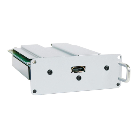
T-1 Trunk Card
KX-TDA0187
(for U.S.A.)
2003 PanasonicCommunications Co., Ltd. All rights reserved.
Unauthorized copying and distribution isaviolation of law.
1
IMPORTANT INFORMATION ABOUT LEAD FREE, (PbF),
SOLDERING
If leadfree solderwas usedinthe manufacture of this product the printedcircuit boards will be
markedPbF, Standardladed, (Pb), soldercanbe usedas usual on boards without the PbF mark.
Whenthis mark does appearplease readand followthe special instructions describedinthis
manual on the use of PbF and howit might be permissible touse Pbsolderduring service and
repairwork.
1. ABOUT LEAD FREE SOLDER (PbF: Pb Free)
Note:
Inthe information below, Pb, the symbol forleadinthe periodic table of elements, will referto
standardsolderorsolderthat contains lead.
2
We will use PbF solderwhendiscussing the leadfree solderusedinourmanufacturing process
whichis made fromTin, (Sn), Silver, (Ag), and Copper, (Cu).
This model, and others like it, manufacturedusing leadfree solderwill have PbF stampedon
the PCB. Forservice and repairwork we suggest using the same type of solderalthough, with
some precautions, standardPbsoldercanalsobe used.
Caution
-PbF solder has amelting point that is50° ~ 70° F, (30° ~ 40°C)
higher than Pb solder. Please use asoldering iron with
temperature control and adjust itto 700° ± 20° F, (370° ± 10°C). In
case of using high temperature soldering iron, please be careful
not to heat too long.
-PbF solder will tend to splash ifitisheated much higher than its
melting point, approximately1100°F, (600°C).
-Ifyou must use Pb solder on aPCB manufactured using PbF
solder, remove as much of the original PbF solder as possibleand
be sure that anyremaining ismelted prior to applying the Pb
solder.
-When applying PbF solder to doublelayered boards, please check
the component side for excess which mayflow onto the opposite
side (See figure, below).
1.1. SUGGESTEDPBFSOLDER
There are several types of PbF solderavailable commercially. While this product is
manufacturedusing Tin, Silver, and Copper,(Sn+Ag+Cu), you canalsouse Tinand Copper, (Sn+
Cu), orTin, Zinc, and Bismuth, (Sn+Zn+Bi). Please check the manufacturer’s specific
instructions forthe melting points of theirproducts and anyprecautions forusing theirproduct
withothermaterials. The following leadfree (PbF) solderwire gauge are recommendedfor
service of this product: 0.3mm, 0.6mm and 1.0mm.
3
1.2. HOWTO RECOGNIZE THATPb FREE SOLDERISUSED
2. FOR SERVICE TECHNICIANS
ICs and LSIs are vulnerable tostatic electricity.
Whenrepairing, the following precautions will helpprevent recurring malfunctions.
1. Cover the plasticpart's boxes with aluminum foil.
2. Ground the soldering irons.
3. Use aconductive mat on the worktable.
4. Donot touch the ICor LSI pins with bare fingers.
3. SPECIFICATIONS
4
4. NAMES AND LOCATIONS
Overview
Inside View
5
Note:
*Null slot is not available foranyoptional service cards.
4.1. INSTALLING/REMOVING THEOPTIONALSERVICECARDS
Slot Condition
CardType Slot Type
KX-TDA100:Free Slots 1 to5
KX-TDA200:Free Slots 1 to10 Option Slot MPR Slot
MPR Card No No Yes
CO Line Cards Yes No No
Extension Cards Yes No No
OPB3 Card Yes Yes No
CTI-LINK Card Yes Yes No
Caution:
To protect the back boardfromstatic electricity, do not touchparts on the back boardinthe
mainunit and on the optional service cards. To discharge static, touchground orwearan
earthing strap.
Function
1-port T1 CO line card. EIA/TIA standardcompliant.
6
Accessoryand User-suppliedItems
Accessory(included): ferrite core x 1
User-supplied(not included): RJ45 connector
Notes
-Connect thisoptional service card to the CO line through NT1; do
not connect to the CO line directly.
-T1 Card must be installed behind an FCC registered and ULor CSA-
NRTL listed CSU.
-When connecting the RJ45 connector, attach the included ferrite
core. Refer to "Attaching aFerrite Core to the RJ45 Cable".
-To confirm the CO line connection, refer to "Confirming the CO
Line Connection" in"Starting the HybridIP-PBX".
CAUTION
T1 ports are SELV ports and shouldonlybe connected to SELV
services.
SwitchSettings
Switch Type Usage and Status Definition
A/B Slide Keepthe switchat default A position.
Donot change the position of this switch.
PinAssignments
RJ45 Connector
7
No. Signal Name Level [V] Function
1RX+ (+) Receive data (+)
2 RX- (-) Receive data (-)
3 Reserved - -
4TX- (-) Transmit data (-)
5TX+ (+) Transmit data (+)
6-8 Reserved - -
LED Indications
Indication Color Description
CARD STATUS Green/Red OFF: PowerOff
GreenON: Normal (all ports are idle)
GreenFlash(60 times perminute): Normal (a port is inuse)
RedON: Fault (includes reset)
RedFlash(60 times perminute): Out of Service
SYNC-ERR Red OFF: Normal
ON: Alarm
RAI Red OFF: Normal
ON: Alarm (Clock Slave)
Flash(60 times perminute): Alarm (Clock Master)
AIS Red OFF: Normal
ON: Alarm
SYNC Green OFF: Alarm
ON: Normal
Flash(60 times perminute): Normal (Clock Master)
Starting the HybridIP-PBX
CAUTION
-SDMemoryCard must be inserted inthe SDMemoryCard slot of
the MPRcard before start up.
-Before touching the System Clear Switch and the Reset Button,
discharge staticbytouching ground or wearing agrounding strap.
-Once you have started the HybridIP-PBXand ifyou unplug the
HybridIP-PBX, do not perform the following procedures to start
the HybridIP-PBXagain. Otherwise, your programmed data is
cleared. To restart the HybridIP-PBX, refer to "Using the Reset
Button".
8
-The HybridIP-PBXwill continue to be powered even ifthe power
switch isturned "OFF".
-The power supplycord isused as the maindisconnect device,
ensure that the socket-outlet islocated/installed near the
equipment and iseasilyaccessible.
1. Set the System Clear Switch to the "SYSTEM INITIALIZE" position.
2. Plug the AC power cord into the HybridIP-PBXand an AC outlet,
and turn on the HybridIP-PBX.
Note:
For safetyreasons, do not stretch, bend, or pinch the AC power
cord.
3. Press the Reset Button with apointed tool. (The RUN indicator
will flash.)
4. Whilethe RUN indicator isflashing (withinabout 10 s), return the
System Clear Switch to the "NORMAL" position. Depending on
the configuration, initialization takes about 1minto 3min. If
successfullyexecuted, the RUN indicator will stop flashing and be
kept lit.
All data will be clearedand the HybridIP-PBX will be initializedtothe default values. The DPTs
shouldshowthe time as 00:00.
Note:
Use the AC power cord attached to the PSUonly.
9
LED Indications
Indication Color Description
RUN Green OFF: PowerOff (includes normal reset)
ON: PowerOnand running (on-line)
Flash(60 times perminute): PowerOnand starting
Flash(120 times perminute): PowerOnand resetting before system
clear
ALARM Red OFF: Normal
ON: Alarm (CPU stop, alarm foreachcard)
Flash: Alarm (MPR file errorinrestarting)
Confirming the CO Line Connection
Afterinitialization, programthe HybridIP-PBX and establishCO line connection, and thenuse a
PTtoconfirm it.
To confirm, dial [ ] [3] [7] + CO line number(3 digits) orpress S-CO button (CO01 toCO64).
You will heara dial tone if CO line is available and connected.
Using the Reset Button
If the HybridIP-PBX does not operate properly, use the Reset Button. Before using the Reset
Button, trythe systemfeature againtoconfirm whetherthere definitelyis a problemornot.
Note:
1. When the System Clear Switch isset to "NORMAL", pressing the
Reset Button causes the following:
-Camp-on iscleared.
-Callson holdare terminated.
-Callson exclusive holdare terminated.
-Callsinprogress are terminated.
-Call park iscleared.
Other data stored inmemory, except the above, are not cleared.
2. When the System Clear Switch isset to the "SYSTEM INITIALIZE"
position, you must press the Reset Button with caution, because
all data stored inmemorywill be cleared bythe following
operation: (1) pressing the Reset Button and then, (2) setting the
System Clear Switch to the "NORMAL" position whilethe RUN
indicator isflashing (withinapproximately10 s).
10
Operation
1. Ifthe HybridIP-PBXdoes not operate properly:
A. Make sure that the System Clear Switch isset to the
"NORMAL" position.
B. Press the Reset Button.
2. Ifthe HybridIP-PBXstill does not operate properly:
A. Set the System Clear Switch to the "SYSTEM INITIALIZE"
position.
B. Press the Reset Button.
C. Return the System Clear Switch to the "NORMAL" position
whilethe RUN indicator isflashing (withinapproximately10 s).
Note:
Asaresultof Step 2, all the programmed data will be cleared.
3. Ifthe HybridIP-PBXstill does not work, unplug the HybridIP-PBX
and plug itinagainafter 5minutes.
4. Ifthe HybridIP-PBXstill does not work:
A. Unplug the HybridIP-PBX.
B. Set the System Clear Switch to the "SYSTEM INITIALIZE"
position.
C. Plug inthe HybridIP-PBX.
D. Press the Reset Button.
E. Set the System Clear Switch to the "NORMAL" position while
the RUN indicator isflashing (withinapproximately10 s).
Installing Optional Service Cards
11
1. Insert the card along the guide rails.
2. Holding the card as follows, push the release lever inthe direction
of the arrow so that the card ismade to engage with the
connector on the back board securely.
3. Turn the 2screwsclockwise to fixthe card.
12
5. TROUBLESHOOTING GUIDE
13
14
15
16
6. BLOCK DIAGRAM
7. CIRCUIT OPERATION
7.1. CPUPERIPHERALFUNCTION
The CPU (IC1) is a single chipmicrocomputerof RISC architecture.
This itemdescribes a memoryinterface (program& work) and peripheral functions.
7.1.1. Memory(Program & Work)
Table.5.1 List of the memory(program& work)
Part Name Size Purpose Remarks
Flash
(IC5) 4Mbit
(256K x 16) Program
Area Flashmemoryis employedforthe software
downloading byon-board.
SRAM
(IC3) 4Mbit
(256K x 16) Work Area
17
7.1.2. ChipSelect Logic
Table.5.2 Table of ChipSelect Terminals
Terminals Function
used Wait Function
(Numeral is no. of
clocks.)
Remarks
CS
Terminals Individual
Output (1) Individual
Output (2)
nCS0 (area
0) - - nCS0 1+Programable or1+
Programable+WAIT
Terminals
UsedforFlash
memory
nCS1 (area
1) nCASH
(DRAM) -nCS1 Read1/Write 2 or2+
WAITTerminals UsedforASIC (
IC2)
nCS2 (area
2) - - nCS2 1+Programable or1+
Programable+WAIT
Terminals
UsedforSRAM (
Basic)
Work Area
nCS3 (area
3) nCASL
(DRAM) -nCS3 Read1/Write 2 or2+
WAITTerminals CS Reserve
nCS4 (area
4) PA0 (I/O) TIOCA0
(Timer) nCS4 Read1/Write 2 or2+
WAITTerminals CS Reserve
nCS5 (area
5) PA1 (I/O) nRAS (DRAM) nCS5 Read1/Write 2 or2+
WAITTerminals CS Reserve
nCS6 (area
6) PA2 (I/O) TIOCB0
(Timer) nCS6 1+Programable or1+
Programable+WAIT
Terminals
Usedfor
peripheral
Usedforframer
IC,
CS.
nCS7 (area
7) PA3 (I/O) nWAIT nWAIT Read1/Write 2 or2+
WAITTerminals UsedforInput
Wait
Terminals.
Table.5.3 Table of ChipSelect Port allocation
ChipSelect Address Device Bit
Wide Assignment
Device Bus Cycle Remarks
nCS0 0000000h
l
0FFFFFFh
16bit Flash
(IC5) 2 Clock (1+Long
Wait1) Port allocation of word
by
static bus sizing Bus
cycle
has same setting as
Area
(nCS2).
nCS1 1000000h
l
1FFFFFFh
8bit ASIC
(IC2) 2+WAITTerminals Port allocation of byte
by
static bus sizing.
nCS2 A000000h
l
AFFFFFFh
16bit SRAM
(IC3) 2 Clock (1+Long
Wait1) Port allocation of word
by
static bus sizing Bus
cycle
has same setting as
Area
(nCS0).
nCS6 6000000h
l
6FFFFFFh
8bit T1_IC
(IC302) 3 Clock (1+Long
Wait2) Port allocation of byte
by
static bus sizing.
18
7.1.3. Interrupt
Fig.5.1 External interrupt image
Note:
-nHALT signal isconsistent with the existing PBXand performs
polling byI/O port.
However, when the CPU(IC1) goes to Sleep Mode at HALT, the
CPU(IC1) isenabled for interruption on release nHALT and return
from Sleep Mode.
-The nIRQ[0] interrupt of ASIC(IC2) isset to output and the
interrupt output isto the CPU(IC1) (Mainly, DPRAM
communication interrupts).
-The LOSsignal of the T1-IC(IC302) isalevel output which goes "H
level"at the line reference lost. Thus, edge interruption is
availableat the line reference lost byinputting the inversion signal
of the LOSto the CPU(IC1). The polling operation isalso possible
bysetting the nIRQ4terminal of the CPU(IC1) to i/oport.
19
(The configuration with the interruption processing isto give a
consistencywith the existing PBX.)
-Since the nRxMF signal of the T1-IC(IC302) occurs inperiodic
frame timing, the polling byi/oport isimpossible.
7.2. LINEINTERFACEFUNCTION
7.2.1. Line Interface Outline
T1 carduses the T1-IC (IC302)(Mitel) as the IC forthe line interface. Fig. 5.2 shows the outline
block diagramof the T1-IC (IC302) and Fig. 5.2 shows the characteristics of the T1-IC (IC302).
Also, see the T1-IC (IC302) Data Sheet forthe detailedspecifications.
Fig.5.2 Outline block diagramof the T1-IC (IC302)
Table.5.4 Characteristics of the T1-IC (IC302)
Item Contents Remarks
Line Extraction Clock 1.544MHz
DPLL LowJitterDPLL forclk generation
Elastic Buffer Two-frame elastic buffer(Rx & Tx)
Signaling Controller -HDLC0:ESF Data Link
(4kbps)
-HDLC1:DS1Channel24
(56 or 64kbps)
Built-intwopieces
FIFO (HDLC0) 128Byte x 2 TX/RX Variable inthe range from16
Byte
to128Byte inincrements of 16Byte.
FIFO (HDLC1) 128Byte x 2 TX/RX Variable inthe range from16
Byte
to128Byte inincrements of 16Byte.
PCM HighwayInterface ST-BUS Interface (2.048Mbps)
P-Interface 8bit parallel Bus (Intel/Motorola) UsedIntel Mode forT1 Card.
20

Other Panasonic Network Hardware manuals
Panasonic Schottky Barrier Diodes MA2SE01 User manual

Panasonic

Panasonic Schottky Barrier Diodes MA2SE01 User manual

Panasonic PIN diodes MA27P110G User manual

Panasonic

Panasonic PIN diodes MA27P110G User manual

Panasonic LJ-SK56A User manual

Panasonic

Panasonic LJ-SK56A User manual

Panasonic Switching Diodes MA2Z001 User manual

Panasonic

Panasonic Switching Diodes MA2Z001 User manual

Panasonic E series User manual

Panasonic

Panasonic E series User manual

Panasonic PIN Diodes MA2SP060G User manual

Panasonic

Panasonic PIN Diodes MA2SP060G User manual

Panasonic GA-ML Series User manual

Panasonic

Panasonic GA-ML Series User manual

Panasonic TY-FB7HM User manual

Panasonic

Panasonic TY-FB7HM User manual

Panasonic Transistors 2SC3936G User manual

Panasonic

Panasonic Transistors 2SC3936G User manual

Panasonic Photo IC PNA4601M User manual

Panasonic

Panasonic Photo IC PNA4601M User manual

Panasonic Schottky Barrier Diodes MA3Z792DG User manual

Panasonic

Panasonic Schottky Barrier Diodes MA3Z792DG User manual

Panasonic WJ-NT104 User manual

Panasonic

Panasonic WJ-NT104 User manual

Panasonic Phototransistors PNZ154NC User manual

Panasonic

Panasonic Phototransistors PNZ154NC User manual

Panasonic Circuit Protector Elements UNHZ203 User manual

Panasonic

Panasonic Circuit Protector Elements UNHZ203 User manual

Panasonic K-NL304K/G User manual

Panasonic

Panasonic K-NL304K/G User manual

Panasonic TY-FB8HM User manual

Panasonic

Panasonic TY-FB8HM User manual

Panasonic WJPB65M16 - VIDEO OUTPUT BOARD-WJSX650... User manual

Panasonic

Panasonic WJPB65M16 - VIDEO OUTPUT BOARD-WJSX650... User manual

Panasonic Schottky Barrier Diodes MA3J745EG User manual

Panasonic

Panasonic Schottky Barrier Diodes MA3J745EG User manual

Panasonic Transistors 2SC4562G User manual

Panasonic

Panasonic Transistors 2SC4562G User manual

Panasonic BB-HCS301A - Network Camera Server Operating instructions

Panasonic

Panasonic BB-HCS301A - Network Camera Server Operating instructions

Panasonic Transistors 2SA2084 User manual

Panasonic

Panasonic Transistors 2SA2084 User manual

Panasonic Transistors 2SC3938G User manual

Panasonic

Panasonic Transistors 2SC3938G User manual

Panasonic i-pro WJ-NT304 User manual

Panasonic

Panasonic i-pro WJ-NT304 User manual

Panasonic Schottky Barrier Diodes MA27D270G User manual

Panasonic

Panasonic Schottky Barrier Diodes MA27D270G User manual

Popular Network Hardware manuals by other brands

LG-Nortel ipLDK-60 installation manual

LG-Nortel

LG-Nortel ipLDK-60 installation manual

Crestron 2 Channel Inductor Module CLX-2IND Specification sheet

Crestron

Crestron 2 Channel Inductor Module CLX-2IND Specification sheet

EnGenius ECB350 user manual

EnGenius

EnGenius ECB350 user manual

Advantech PCLD-8751 user manual

Advantech

Advantech PCLD-8751 user manual

Waveshare RS232/485 TO WIFI POE ETH (B) user manual

Waveshare

Waveshare RS232/485 TO WIFI POE ETH (B) user manual

HP Ethernet Network Interface Card hn230e quick start guide

HP

HP Ethernet Network Interface Card hn230e quick start guide

Cabletron Systems CBUPRI/E1 user manual

Cabletron Systems

Cabletron Systems CBUPRI/E1 user manual

DEOS OPEN 600 EMS datasheet

DEOS

DEOS OPEN 600 EMS datasheet

Anviz EasyStore Quick guides

Anviz

Anviz EasyStore Quick guides

Bosch PHANTOM EDGE installation manual

Bosch

Bosch PHANTOM EDGE installation manual

ADTRAN NetVanta T1/FT1 + DSX-1 quick start guide

ADTRAN

ADTRAN NetVanta T1/FT1 + DSX-1 quick start guide

A&D AD-4411 instruction manual

A&D

A&D AD-4411 instruction manual

SIGMA TEK FDD Power Installation Guide

SIGMA TEK

SIGMA TEK FDD Power Installation Guide

8e6 Technologies Enterprise Filter Authentication R3000 quick start guide

8e6 Technologies

8e6 Technologies Enterprise Filter Authentication R3000 quick start guide

KT&C KNR-p16Px16 Quick installation guide

KT&C

KT&C KNR-p16Px16 Quick installation guide

Juniper CTP2000 Series Hardware guide

Juniper

Juniper CTP2000 Series Hardware guide

NETWEEN NVR Quick installation guide

NETWEEN

NETWEEN NVR Quick installation guide

GeoVision GV-NVR System Lite user manual

GeoVision

GeoVision GV-NVR System Lite user manual

manuals.online logo
manuals.online logoBrands
  • About & Mission
  • Contact us
  • Privacy Policy
  • Terms and Conditions

Copyright 2025 Manuals.Online. All Rights Reserved.