manuals.online logo
Brands
  1. Home
  2. •
  3. Brands
  4. •
  5. Panasonic
  6. •
  7. Projector Accessories
  8. •
  9. Panasonic PressIT TY-WPSC1 User manual

Panasonic PressIT TY-WPSC1 User manual

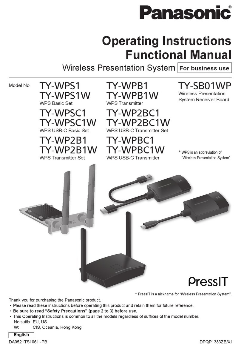
Operating Instructions
Basic Guide
Wireless Presentation System
For business use
Model No. TY-WPS1
WPS Basic Set
TY-WP2B1
WPS Transmitter Set
TY-WP2BC1
WPS USB-C Transmitter Set
TY-WPSC1
WPS USB-C Basic Set
TY-WPB1
WPS Transmitter
TY-WPBC1
WPS USB-C Transmitter
* WPS is an abbreviation of “Wireless
Presentation System”.
Thank you for purchasing the Panasonic product.
• Please read these instructions before operating this product and retain
them for future reference.
•Be sure to read “Safety Precautions ” (page 2 to 4) before use.
• These Operating Instructions are shared by TY-WPS1, TY-WPSC1,
TY-WP2B1, TY-WPB1, TY-WP2BC1 and TY-WPBC1.
DPQX1530ZD/X1DA0920TS3051 -PB
Accessories 5
Safety Precautions 2
Part Names 6
Fixing the Transmitter Connection 12
Connection 8
Basic Use 10
Transmitter Extension Method (Pairing)
13
Installing the Receiver 15
Notes on Using Wireless LAN 17
Request Regarding Security 19
Specifications 21
English
2 English
Safety Precautions
WARNING:
Stop using the product immediately when an
abnormality or malfunction occurs.
Remove the power plug in the case of an
abnormality.
• Smoke is emitted, or abnormal smell or sound occurs.
• Video or audio is not reproduced in some cases.
• Liquid such as water or a foreign object has entered
inside the product.
• The product is deformed or damaged.
Using the product in such states may cause a fire or
electric shock.
• Remove the power plug from the outlet and request
repair to the dealer where you purchased the product.
• It is necessary to remove the power plug to completely
turn off the power of this product.
• Do not repair the product by the customer since it is
dangerous.
• Use an outlet located at a position where the hand can
reach easily so that the power plug can be removed
quickly.
Do not insert foreign objects into the product.
Do not insert or drop metals or flammable items into the
inside the product from the vent hole, etc.
Smoke is emitted, or abnormal smell or sound occurs.
• Keep an eye on children in particular.
■About AC adaptor
Do not use an AC adaptor or AC adaptor cable other
than those supplied with this product.
Using an AC adaptor or AC adaptor cable other than
those supplied may cause an electric shock or fire due to
short circuit or heat generation.
Clean the power plug periodically to prevent dust
from accumulating.
Failure to do so may cause a fire or electric shock due
to moisture.
• Remove the power plug and wipe it with dry cloth.
Do not insert or remove the power plug with wet
hand.
Doing so may cause an electric shock.
Do not use the outlet or wiring devices exceeding
rated values or with currents other than 100 ‒ 240 V
AC.
Using them exceeding rated values by connecting too
many plugs in one outlet may cause a fire due to heat
generation.
Insert the power plug securely to the end.
Insufficient insertion may cause a fire due to an electric
shock or heat generation.
• Do not use the product with a damaged plug or loose
outlet.
3English
Do not damage the AC adaptor and power plug.
by damaging, modifying, forcibly bending, twisting,
pulling or bundling them, bringing them close to heat
appliances, placing heavy items on them, etc.
Doing so may cause a fire or electric shock due to short
circuit or disconnection.
• Request the dealer for repair of the AC adaptor or
power plug.
Use the product 15 cm or more away from a location
where a cardiac pacemaker is embedded.
Radio waves may affect the operation of the pacemaker.
Do not use the product in an airplane.
The operational safety may be impaired.
Do not use the product near an automatic door, fire
alarm or other automatic control devices.
Radio waves from this product may affect automatic
control devices, which may cause an operational error,
resulting in an accident.
Do not use the product in hospital or a location with
medical equipment.
Radio waves from this product may affect medical
equipment, which may cause an operational error,
resulting in an accident.
Do not use the product while touching it for a long
time.
Touching the hot parts of the product and AC adaptor for
a long time may cause a low-temperature burn*.
* Persons with poor bloodstream (due to vascular
impairment, poor blood circulation, diabetes or strong
compression) or poor skin sensitivity (elderly persons)
tend to get a low-temperature burn.
Do not touch the product and AC adaptor if it begins
to thunder.
Doing so may cause an electric shock.
Do not wet the product.
Doing so may cause a fire or electric shock.
Do not place the product on unstable locations.
Placing the product on a shaky table or an inclined location
may cause an injury due to falling over or dropping.
Do not remove or modify the back cover (cabinet).
Keep the screws supplied with the receiver out of
reach of infants.
The screws may be accidentally swallowed.
• In the event this occurs, consult a doctor immediately.
For installation, please ask a qualified technician or
a dealer.
If installation is not carried out and secured correctly, it
can cause falling accidents.
Do not touch the bottom surface of the transmitter
during use.
The bottom surface of the transmitter may be hot during
and after use for a while, resulting in a burn injury.
Also, do not place it on an object sensitive to heat. Doing
so may cause deformation or discoloration.
4 English
Safety Precautions Continued
CAUTION:
Do not block the vent hole of this product.
Do not push the product into a narrow and poorly
ventilated space.
Doing so may cause heat to accumulate inside, resulting
in a fire or malfunction.
Do not place a heavy item on the product.
Doing so may cause a fire or malfunction.
Do not place the product at a high-temperature
location, humid or dusty location, or location subject
to oil smoke or steam (such as a cooking table and
humidifier).
Doing so may cause a fire or electric shock.
When removing the connection cables, be sure to
hold the connector and pull it.
Pulling the cord may damage the cord, resulting in a fire
due to an electric shock or short circuit.
When transferring the product, remove the
connection cables of equipment beforehand.
Failure to do so may damage the cord or product,
resulting in a fire or electric shock.
When not using the product for a prolonged period,
remove the power plug from the outlet.
Dust may accumulate in the power plug, resulting in a
fire or electric shock.
Do not pull or hang the connection cables.
Doing so may cause the product to fall over or drop,
resulting in an injury.
• Keep an eye on children in particular.
■Maintenance
For maintenance, remove the power plug from the
outlet for safety.
Failure to do so may cause an electric shock.
5English
Accessories
Check that you have the accessories and items shown.
WPS Basic Set TY-WPS1
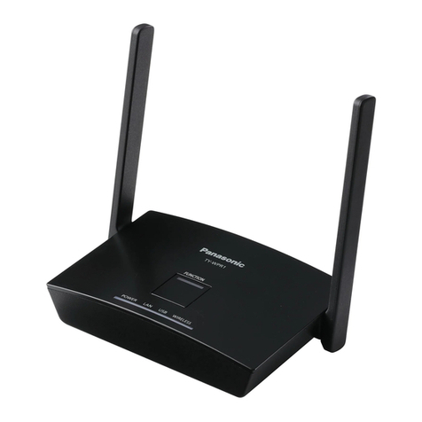
WPS Receiver
(TY-WPR1) ........... 1
WPS Transmitter
(TY-WPB1) ........... 2
Transmitter case
(TY-WPC1) ........... 1
AC adaptor
(DPVF3514ZA/X1)
...1
(including 3
conversion plugs)
AC adaptor cable
(DPVF3515ZA/X1)
...1
HDMI cable
(DPVF3512ZA/X1)
...1
USB extension cable
(DPVF3513ZA/X1)
...2
Receiver mounting
bracket
(see page 15) .......1
WPS USB-C Basic Set TY-WPSC1
WPS Receiver
(TY-WPR1) ........... 1
WPS USB-C Transmitter
(TY-WPBC1) .........2
Transmitter case
(TY-WPC1) ........... 1
AC adaptor
(DPVF3699ZA/X1)
...1
(including 4
conversion plugs)
AC adaptor cable
(DPVF3515ZA/X1)
...1
HDMI cable
(DPVF3512ZA/X1)
...1
Conversion adaptor
for pairing
(DPVF3516ZA/X1)
...1
Receiver mounting
bracket
(see page 15) .......1
WPS Transmitter Set TY-WP2B1
WPS Transmitter
(TY-WPB1) ........... 2
Transmitter case
(TY-WPC1) ........... 1
USB extension cable
(DPVF3513ZA/X1)
...2
WPS Transmitter TY-WPB1
WPS Transmitter
(TY-WPB1) ........... 1
USB extension cable
(DPVF3513ZA/X1)
...1
WPS USB-C Transmitter Set TY-WP2BC1
WPS USB-C
Transmitter
(TY-WPBC1) .........2
Transmitter case
(TY-WPC1) ........... 1
Conversion adaptor
for pairing
(DPVF3516ZA/X1)
...1
WPS USB-C Transmitter TY-WPBC1
WPS USB-C
Transmitter
(TY-WPBC1) .........1
Conversion adaptor
for pairing
(DPVF3516ZA/X1)
...1
Attention
• Store small parts in an appropriate manner, and keep
them away from young children.
• The part numbers of accessories are subject to
change without notice.
(The actual part number may differ from the ones
shown above.)
• In case you lost accessories, please purchase them
from your dealer. (Available from the customer service)
• Dispose the packaging materials appropriately after
taking out the items.
6 English
1
3
2
4
5 6 7 8 109 11
Part Names
1Antenna
2FUNCTION button / LED
Used to save a pairing file to the USB memory.
3Indicator
Displays the power supply status, and connection
statuses of LAN and USB.
4
Screw holes for mounting bracket (page 15)
Used to attach the receiver to the mounting bracket.
▼Connectionterminals/Controls
5Security Slot
This security slot is compatible with a Noble Wedge
slot.
6Power input terminal
7Power button
Turns ON/OFF the power of the receiver.
8Reset button
Restores the product to the factory default state.
9USB terminal (Type-A)
Connects the transmitter or USB memory when
pairing devices.
10 LAN terminal (RJ45)
Connects to the network to change the settings of the
product.
11 HDMI output terminal
Connects an imaging device equipped with HDMI input.
▼Connectionterminals/Controls
■Receiver (TY-WPR1)
7English
24
1
3
7
3 4
65
5 6
1HDMI input terminal
Connect to an imaging device equipped with HDMI
output.
2USB terminal (Type-A)
Connect to a USB power supply device.
3Main button / LED
Switches between on and off of image display.
4Sub button / LED
Switches to the multi-screen mode.
5Mode switch
It is used when pairing.
6USB terminal (Type-A)
Connects a USB memory when pairing with the
receiver.
7USB terminal (Type- C)
Connect to an imaging device with USB Type-C
output.
■Transmitterr (TY-WPB1)
■USB-C transmitterr (TY-WPBC1)
■Transmitter case
2 transmitters and the USB extension
cable can be stored.
8 English
Connection
Before connection, carefully read the operation manual
of the device to be connected to this system.
Turn off the power of each device before connecting
cables.
Connecting the receiver
1Connect the AC adaptor and AC adaptor
cable to the receiver for power supply.
Use an AC adaptor conversion plug that fits the
shape of outlet.
<How to remove>
1
Press the button
2
Remove the plug
2
1
Note
• Do not remove the AC adaptor conversion plug
while it is connected to the outlet.
2Connect a display device such as a display
and projector to the receiver with HDMI
cable.
HDMI cable
Display or projector
AC adaptor
AC adaptor cable
Note
• For power supply to the receiver, use the supplied
AC adaptor or a USB power supply device with
5 V/2 A.
9English
3Press the power button of the receiver.
When a standby screen is displayed on the
display device, the receiver has completed
preparation.
Standby screen
Connecting the transmitter
1Connect the USB terminal and HDMI input
terminal of the transmitter to the image
output device.
• For power supply to the transmitter, 5 V/0.9 A
power supply is necessary.
HDMI input
terminal
TY-WPBC1
USB terminal
TY-WPB1
For the USB-C transmitter, connect the USB terminal
(Type-C) to the image output device.
2
Main LED changes from red blinking
(connecting) to white illumination (standby).
Red blinking (connecting) White illumination
(standby)
10 English
Basic Use
Single connection
This section describes how to display an image using
one transmitter.
1Press the main button of the transmitter
while the standby screen is displayed.
The image is displayed.
Standby screen Full screen display
White illumination
(standby)
Green illumination
(display)
Pressing the main button again changes the main
LED to white and returns to standby state.
(The screen returns to the standby screen as well.)
• When using multiple transmitters, the image is
switched to the image of the transmitter of which
the main button is pressed.
Multi connection
This section describes how to display images
simultaneously using multiple transmitters.
Images of up to 4 transmitters can be displayed
simultaneously.
1Press and hold the sub button of the
transmitter for 1 seconds or more during
full screen display.
The sub LED changes to green illumination, and the
multi-screen mode is enabled.
Full screen display
11
1 11 1
Sub LED
OFF
Sub LED
Green illumination
(Multi-screen mode)
11English
2Press the main button of the transmitter of
which the image is to be added.
The image is added.
Full screen display
11
Multi-screen display
1122
2 22 2
White
illumination
(standby)
Green
illumination
Sub LED
Green
illumination
Sub LED
Green
illumination
Multi-screen mode cancellation
Press and hold the sub button of the transmitter
for 1 seconds or more.
• The sub LED changes from green illumination to
OFF state, and the multi-screen mode is canceled.
Details of usage
For details of usage, read “Operating Instructions -
Functional Manual”.
Download the “Operating Instructions - Functional
Manual” from the following URL.
https://panasonic.net/cns/prodisplays/wps2/
12 English
Fixing the Transmitter Connection
While multiple transmitters are paired and used, you can
connect only one transmitter to the receiver and disable
switching to another transmitter.
This setting prevents accidental transmitter-switching
operation.
Setting the fixed mode
Press and hold the main button of the
transmitter for 1 seconds or more while an
image of one transmitter is displayed.
The main LED changes from green illumination to blue
illumination, and the fixed mode is enabled.
1111
1 11 1
Green illumination Blue illumination (fixed mode)
Other transmitters
2 22 2
White illumination
(standby)
Red illumination
(operation disabled)
Canceling the fixed mode
Press and hold the main button of the
transmitter for 1 seconds or more.
The main LED changes from blue illumination to green
illumination, and the fixed mode is canceled.
1 11 1
Blue illumination
(fixed mode)
Green illumination
(fixed mode canceled)
13English
Transmitter Extension Method (Pairing)
Pairing settings have been made for transmitter and
receiver of TY-WPS1 Basic Set / TY-WPSC1 Basic Set.
Pairing by connecting the receiver and
transmitter
1Slide the mode switch to the STD side.
2
Connect the USB terminal of the transmitter
to the USB terminal of the receiver.
TY-WPBC1TY-WPB1
To connect the TY-WPBC1,
use the conversion adaptor for
pairing supplied with the
TY-WPSC1/TY-WP2BC1/
TY-WPBC1.
Wait for a while until the LED of the receiver blinks in
white. Then, pairing starts automatically.
“Pairing…” (pairing in progress) is displayed on the
standby screen.
3Pairing is complete.
“Pairing OK” is displayed and the LED of the receiver
lights up in white.
Pairing... Pairing OK
4Remove the USB cable of the transmitter
from the receiver.
14 English
Pairing by saving a file to the USB memory
Supported device
●Commercially available USB memory devices are
supported. (Those with security functions are not
supported.)
●USB memory devices other than those formatted in
FAT16 or FAT32 cannot be used.
●Up to 32 GB of USB memory in size are supported.
●Only single partition configuration is supported.
1Connect the USB memory to the USB
terminal of the receiver.
1
2
2Press the FUNCTION button.
The LED lights up in white and the pairing file is
saved to the USB memory.
3Remove the USB memory.
4Slide the mode switch to the EXT side.
5Supply power to the transmitter.
6
5
6
5
TY-WPB1
TY-WPBC1
5 V/0.9 A
Power supply
5 V/0.9 A
Power supply
6Connect the USB memory to the USB
terminal of the transmitter.
7Pairing is complete.
The main LED of the transmitter lights up in white.
8Remove the USB memory from the
transmitter.
Transmitter Extension Method (Pairing) Continued
15English
Installing the Receiver
Components for receiver mounting bracket
Check the following parts are included.
Base bracket (A-1).................1
(DPVF3503ZA/X1)
Connecting bracket A (A-2) ..1
(DPVF3505ZA/X1)
Used to install on the display.
Connecting bracket B (A-3)
….1
(DPVF3504ZA/X1)
Used to install on the display.
Connecting bracket C (A-4)
....1
(DPVF3506ZA/X1)
Used to install on the projector.
Sheet A (B-1) ..........................1
(DPVF3507ZA/X1)
(30 × 12 mm)
Sheet B (B-2)..........................3
(DPVF3508ZA/X1)
(24 × 20 mm)
Knurled screw (C-1)...............2
(DPVF3509ZA/X1)
(M4 × 5)
Screw (C-2) ............................6
(DPVF3510ZA/X1)
(M4 × 5)
Screw (C-3) ............................2
(DPVF3511ZA/X1)
(M3 × 8)
Installing on the ceiling or wall
1Place the base bracket (A-1) aligning it with
the 4 screw holes on the bottom surface of
the receiver.
2Fix the base bracket (A-1) with 4 screws
(C-2).
C-2
A-1
The base bracket can be mounted in either vertical or
horizontal direction.
16 English
3Fix the receiver to the ceiling or wall with
2 screws.
Use screws (commercially available) of the
appropriate type and length according to the ceiling
or wall to be installed. (Recommended size: M4)
Other installation method
The receiver can be installed on the display or projector.
●Installing on the display
●Installing on the projector
For details of installation method, read “Operating
Instructions - Functional Manual”.
Download the “Operating Instructions - Functional
Manual” from the following URL.
https://panasonic.net/cns/prodisplays/wps2/
Installing the Receiver Continued
17English
Notes on Using Wireless LAN
Wireless LAN uses radio waves in the 5 GHz bands.
Be sure to read and fully understand the following items
before use.
Use this product indoors.
●Using the 5 GHz-band wireless device outdoors is
prohibited by the Radio Act.
If at all possible, avoid the use of cellular phones, TV
sets or radios near the product.
●Cellular phones, TV sets, radios and similar devices
use different radio bands from the product, so
there is no effect on wireless communication or the
transmission and reception of these devices. However,
radio waves from the product may produce audio or
video noise.
Wireless communication radio waves cannot
penetrate steel reinforcements, metal, concrete, etc.
●Communication is possible through walls and floors
made from materials such as wood and glass (except
glass containing wire mesh), but not through walls
and floors made from steel reinforcements, metal,
concrete, etc.
The product may not work properly due to strong
radio wave from the broadcast station or the radio.
●If there is any facility or equipment, which outputs
strong radio wave, near the installation location, set up
the product at a location sufficiently far from the source
of the radio wave.
Using the product outside the country
●It is forbidden to take the product outside the country
or region where you purchased it, so use it only in
the said country or region. Also, note that depending
on countries or regions there are restrictions on the
channels and frequencies at which you can use the
wireless LAN.
18 English
Declaration of Conformity (DoC)
“Hereby, Panasonic Corporation declares that this
product is in compliance with the essential requirements
and other relevant provisions of the Directive 2014/53/
EU.”
If you want to get a copy of the original DoC of this
product, please visit the following website:
http://www.ptc.panasonic.de
Authorized Representative:
Panasonic Testing Centre
Panasonic Service Europe, a division of Panasonic
Marketing Europe GmbH
Winsbergring 15, 22525 Hamburg, Germany
Indoor use restrictions are to be followed for the following
countries if using 5 GHz frequency band.
Austria, Belgium, Bulgaria, Croatia, Cyprus, Czech
Republic, Denmark, Estonia, Finland, France,
Germany, Greece, Hungary, Iceland, Ireland, Italy,
Latvia, Liechtenstein, Lithuania, Luxembourg, Malta,
Netherlands, Norway, Poland, Portugal, Romania,
Slovakia, Slovenia, Spain, Sweden, Switzerland, Turkey,
United Kingdom
WLAN: Maximum Power
23 dBm (5.180 GHz - 5.240 GHz)
Directive: 2014/53/EU
Notes on Using Wireless LAN Continued
19English
Request Regarding Security
When using this product, take safety measures
against the following incidents.
●Personal information being leaked via this product
●Unauthorized operation of this product by a malicious
third party
●Interfering or stopping of this product by a malicious
third party
Take sufficient security measures.
Precautions on security when
using wireless LAN products
●The advantage of a wireless LAN is that information
can be exchanged between a PC or other such
equipment and an access point using radio waves as
long as you are within range for radio transmissions.
On the other hand, because the radio waves can
travel through obstacles (such as walls) and are
available everywhere within a given range, problems
of the type listed below may occur if security-related
settings are not made.
• A malicious third-party may intentionally intercept
and monitor transmitted data including the content
of e-mail and personal information such as your
ID, password, and/or credit card numbers.
• A malicious third-party may access your personal
or corporate network without authorization and
engage in the following types of behaviour.
Retrieve personal and/or secret information
(information leak)
Spread false information by impersonating a
particular person (spoofing)
Overwrite intercepted communications and issue
false data (tampering)
Spread harmful software such as a computer
virus and crash your data and/or system (system
crash)
●Since most wireless LAN adaptors or access points
are equipped with security features to take care of
these problems, you can reduce the possibility of
these problems occurring when using this product
by making the appropriate security settings for the
wireless LAN device.
●Some wireless LAN devices may not be set for
security immediately after purchase. To decrease the
possibility of occurrence of security problems, before
using any wireless LAN devices, be absolutely sure
to make all security-related settings according to the
instructions given in the operation manuals supplied
with them.
20 English
Depending on the specifications of the wireless
LAN, a malicious third-party may be able to break
security settings by special means.
Please contact Panasonic if you need help taking
care of security settings or other such.
If you cannot perform security settings for your
wireless LAN by yourself, please contact the
Panasonic Support Center.
●Panasonic asks customers to thoroughly understand
the risk of using this product without making security
settings, and recommends that the customer
make security settings at their own discretion and
responsibility.
Request Regarding Security Continued

This manual suits for next models

5

Other Panasonic Projector Accessories manuals

Panasonic ET-PKB50 Installation instructions

Panasonic

Panasonic ET-PKB50 Installation instructions

Panasonic ET-LAL510 User manual

Panasonic

Panasonic ET-LAL510 User manual

Panasonic PressIT TY-WPS1 User manual

Panasonic

Panasonic PressIT TY-WPS1 User manual

Panasonic TY-FB10WPE User manual

Panasonic

Panasonic TY-FB10WPE User manual

Panasonic ET-RFL100 User manual

Panasonic

Panasonic ET-RFL100 User manual

Panasonic PressIT TY-WP2B1W Operating instructions

Panasonic

Panasonic PressIT TY-WP2B1W Operating instructions

Panasonic ET-D3LEW60C User manual

Panasonic

Panasonic ET-D3LEW60C User manual

Panasonic PressIT TY-WP2B1 User manual

Panasonic

Panasonic PressIT TY-WP2B1 User manual

Panasonic ET-EMF510 User manual

Panasonic

Panasonic ET-EMF510 User manual

Panasonic ET-PKD130B User manual

Panasonic

Panasonic ET-PKD130B User manual

Panasonic ET-D75LE6 User manual

Panasonic

Panasonic ET-D75LE6 User manual

Panasonic ET-LAA410 User manual

Panasonic

Panasonic ET-LAA410 User manual

Panasonic PressIT TY-WPS1 User manual

Panasonic

Panasonic PressIT TY-WPS1 User manual

Panasonic ET-SFD320C User manual

Panasonic

Panasonic ET-SFD320C User manual

Panasonic ET-DLE030 User manual

Panasonic

Panasonic ET-DLE030 User manual

Panasonic ET-ELW21 User manual

Panasonic

Panasonic ET-ELW21 User manual

Panasonic ET-UW100 User manual

Panasonic

Panasonic ET-UW100 User manual

Panasonic ET-LAV200 User manual

Panasonic

Panasonic ET-LAV200 User manual

Panasonic ET-LAV100 User manual

Panasonic

Panasonic ET-LAV100 User manual

Panasonic ET-ELT20 User manual

Panasonic

Panasonic ET-ELT20 User manual

Panasonic ET-D3LEU100 User manual

Panasonic

Panasonic ET-D3LEU100 User manual

Panasonic ET-PKE200H User manual

Panasonic

Panasonic ET-PKE200H User manual

Panasonic Panaboard KX-BP535 User manual

Panasonic

Panasonic Panaboard KX-BP535 User manual

Panasonic ET-LAL330 User manual

Panasonic

Panasonic ET-LAL330 User manual

Popular Projector Accessories manuals by other brands

Adeo ALUMAX installation manual

Adeo

Adeo ALUMAX installation manual

Realfiction Dreamoc XL2 Assembly guide

Realfiction

Realfiction Dreamoc XL2 Assembly guide

LP Morgan Resi-Lift manual

LP Morgan

LP Morgan Resi-Lift manual

ScreenBeam 3100 quick start guide

ScreenBeam

ScreenBeam 3100 quick start guide

Sharp AN-PH60EZ Operation manual

Sharp

Sharp AN-PH60EZ Operation manual

Ergo RPA Elite Series installation instructions

Ergo

Ergo RPA Elite Series installation instructions

BenQ 0.4 Wall Mount-WM04G3 user manual

BenQ

BenQ 0.4 Wall Mount-WM04G3 user manual

Sharp AN-PH814EZ Operation manual

Sharp

Sharp AN-PH814EZ Operation manual

Epson ELPLX03 user guide

Epson

Epson ELPLX03 user guide

Marantz VP-10S1 user guide

Marantz

Marantz VP-10S1 user guide

Premier Mounts PDS-LAT installation instructions

Premier Mounts

Premier Mounts PDS-LAT installation instructions

Kingpin BIG SIZE SCREEN A Operation guide

Kingpin

Kingpin BIG SIZE SCREEN A Operation guide

New Star Neomounts BEAMER-C80WHITE instruction manual

New Star

New Star Neomounts BEAMER-C80WHITE instruction manual

Screen Int T-MEDIUM installation manual

Screen Int

Screen Int T-MEDIUM installation manual

B-Tech Mountlogic BT881/B Installation guide & parts list

B-Tech

B-Tech Mountlogic BT881/B Installation guide & parts list

Digitus DS-55319 Quick installation guide

Digitus

Digitus DS-55319 Quick installation guide

Elite Screens ezFrame 2 Series Product White Paper

Elite Screens

Elite Screens ezFrame 2 Series Product White Paper

ClearClick Present+Share Mini Users manual & quick start guide

ClearClick

ClearClick Present+Share Mini Users manual & quick start guide

manuals.online logo
manuals.online logoBrands
  • About & Mission
  • Contact us
  • Privacy Policy
  • Terms and Conditions

Copyright 2025 Manuals.Online. All Rights Reserved.