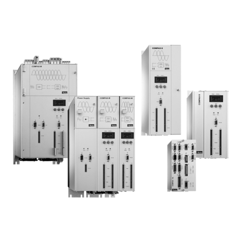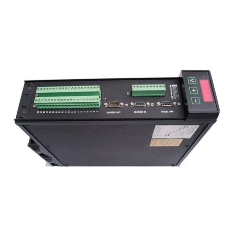
46K Hardware Installation Guide
6K Series General Specifications
Parameter Specification
Power (DC input)................................................... 24 VDC ±10%, 2A max. (current requirements depend on type/amount of I/O used)
Environmental
Operating temperature........................................ 32 to 122°F (0 to 50°C)
Storage temperature........................................... -22 to 185°F (-30 to 85°C)
Humidity.............................................................. 0 to 95% non-condensing
Performance
Command output ................................................ ±10V or Step & Direction
Servo update ...................................................... As fast as 62.5 µs per axis
Stepping accuracy .............................................. ±0 counts from preset total
Position range..................................................... ±2,147,483,648 counts
Velocity range ..................................................... Stepper axes: 1 to 2,000,000 counts/sec; Servo axes: 1 to 12,000,000 counts/sec;
Acceleration range.............................................. 1 to 50,000,000 counts/sec/sec
Communication Interface
Serial
Connection .................................................. RS-232: 3-wire connections (Rx, Tx and GND) on “RS-232” or “RS-232/485”
connectors. The “RS-232/485” connector’s default configuration is for RS-232 and set
for use with an RP240 (see page 32).
RS-485: 2- and 4-wire connections to “RS-232/485” connector. Requires DIP switch
changes (see page 5).
Maximum units in daisy chain ..................... 99 (use ADDR command to set individual addresses for each unit).
Communication parameters ........................ 8 data bits; No parity; Baud: 9600 (set with BAUD command; range: 1200-38400).
Ethernet .............................................................. 10Base-T (10Mbps twisted pair); TCP/IP protocol. RJ-45 connector. Default IP
address is 192.168.10.30 (use NTADDR on RS-232 port to change address).
Onboard Inputs
Encoder inputs.................................................... Differential comparator accepts two-phase quadrature incremental encoders with
differential or single-ended outputs. To use single-ended encoders, jumper pin 8 to
pin 9 (not available on Master Encoder connector). The “Master Encoder” connector
may not be used for servo feedback or stepper stall detect.
Maximum voltage = 5VDC. Switching levels (TTL): Low ≤0.4V, High ≥2.4V.
Maximum frequency = 12.0 MHz post quadrature.
Limit inputs (“LIMITS/HOME” connectors)................ Voltage range = 0-24 VDC. Factory default is sourcing current, voltage reference is
24 VDC*. To make all limit inputs sink current, connect the “LIM-P” terminal to the
“GND” terminal (see connector on top of 6K chassis).
Trigger inputs (“TRIGGERS/OUTPUTS” connectors).. Voltage range = 0-24 VDC. Factory default is sourcing current, voltage reference is
24 VDC*. To make all trigger inputs sink current, connect the “TRIG-P” terminal to the
“GND” terminal (see connector on top of 6K chassis).
Master trigger input (“MASTER TRIG”) .................... (same specification as the rest of the trigger inputs)
Drive Fault input (pin 5 on “DRIVE” connectors) ... Voltage range = 0-24 VDC. Factory default is sourcing current, voltage reference is
24 VDC*. To make all drive fault inputs sink current, connect the “CNTRL-P” terminal
to the “GND” terminal (see connector on top of 6K chassis).
“ENABLE” input .................................................. Voltage range = 0-24 VDC. Voltage reference is 24 VDC*. Internal 6.8 KΩpull-up to
24 VDC. If this input is opened, motion is killed and the program in progress is
terminated. If ENABLE is not grounded when motion is commanded, motion will not
occur, and the error message “WARNING: ENABLE INPUT ACTIVE” will be
displayed to the terminal emulator. (see connector on top of 6K chassis).
Onboard Outputs
Digital outputs (“TRIGGERS/OUTPUTS” connectors). Open-collector outputs; will sink up to 300 mA.
+5VDC output (pin 1 on “ENCODER”) .................... Internally supplied +5VDC. Provides up to 250 mA per encoder.
Servo drive command out (pin 3 on “DRIVE”) ....... Command signal output to the drive. ±10VDC analog output. 12-bit DAC. Load should
be > 2 KΩimpedance.
Servo drive shutdown (pins 7 & OUT DIODE”)8 on “DRIVE”) Shutdown relay output. Max rating: 175VDC, 0.25A, 3W.
Step, Direction, Shutdown (pins 1,2,11 on “DRIVE”) Differential line drive output. Signal high > 3.5VDC @ +30 mA,
signal low < 1.0VDC @ -30 mA. +output for each driver is active high, -output is
active low. Step pulse width is 0.3-20 µs (depending on PULSE command — default is
0.5 µs).
Flyback diode output (“OUT DIODE”) ...................... Connected to 24 VDC power with external jumper — allows you to use internal
flyback diode for onboard outputs that are driving inductive loads.
DISCONNECT the jumper if the onboard outputs are not driving inductive loads.
* The voltage reference (VINref) is +24 VDC, unless you connect an external 5-24 VDC supply to the “VINref” terminal (see connector on
top of 6K chassis). Switching levels: Low ≤1/3 VINref, High ≥2/3 VINref.
www.comoso.com
