Parker Karrykrimp 2 User manual

Karr
y
krimp 2
B
ulletin 44
80
-T7-
US
T
ec
hni
ca
l M
a
n
ua
l
C
rimpin
g
Machine
E
ff
ective: Au
g
ust 2006
S
upersedes: Jul
y
2005

Bulletin 4480-T7-U
S
K
arr
y
krimp
2
P
arker Hanni
fi
n
C
orporation
Hose
Pr
oduc
t
s
Divi
s
i
o
n
W
ickli
ff
e,
OH
2
•
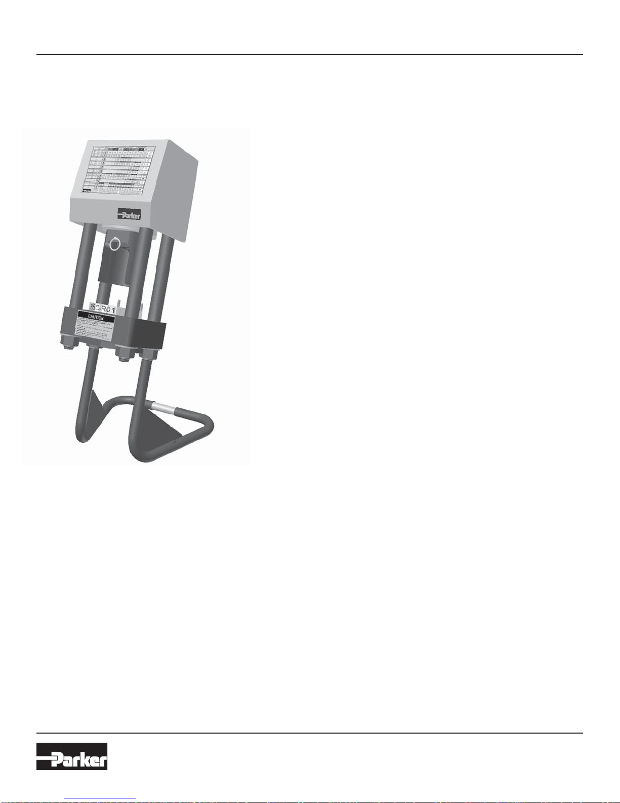
Read the entire Technical Manual prior to mountin
g
and operatin
g
this crimper.
•
View the enclosed video or CD prior to operatin
g
this crimper
.
W
ARNIN
G
- When usin
g
this machine, alwa
y
s exercise basic sa
f
et
y
precautions, includin
g
, but not
limited to the
f
ollowin
g
:
1. Use this machine onl
y
f
or its intended purpose: to
f
abricate Parker hose assemblies.
2. Parker Hanni
fi
n will not accept responsibilit
y
f
or an
y
incidental, consequential or special
dama
g
es o
f
an
y
kind or nature whatsoever that result
f
rom an
y
subsequent alterations to an
y
Parkrimp machine. Parker Hanni
fi
n disclaims an
y
warranties on items altered a
f
ter leavin
g
the
Parker Hanni
fi
n
f
acilit
y
.
3. This machine must be properl
y
installed and located in accordance with the installation
in
s
tr
uc
ti
o
n
s
befo
r
e
it i
s
used
.
To minimize the possibilit
y
o
f
in
j
ur
y
:
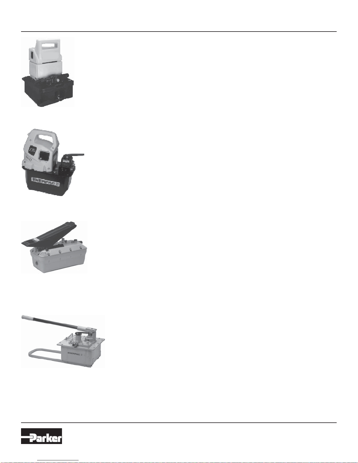
1. The power unit must be connected to a
g
rounded, properl
y
rated, protected and sized
power-supp
ly
c
i
rcu
i
t to prevent e
l
ectr
i
ca
l
s
h
oc
k
an
d
to avo
id
e
l
ectr
i
ca
l
over
l
oa
d
;
2. D
O
N
O
T
O
PERATE
O
VER MAXIMUM RATED W
O
RKIN
G
PRE
SS
URE; AND
3
.
C
HE
C
K F
O
R
S
AFE
S
Y
S
TEM
S
ET
U
P
S.
Make sure that the valve, connectin
g
hoses, etc. are protected
f
rom an
y
external source o
f
dama
g
e, such as: excessive heat,
fl
ame, movin
g
machine parts, sharp ed
g
es,
f
allin
g
ob
j
ects,
corros
i
ve c
h
em
i
ca
l
s, etc.
IMP
O
RTANT
S
AFETY N
O
TI
CE
THI
S
INF
O
RMATI
O
N I
S
INTENDED F
O
R U
S
E BY INDIVIDUAL
S
P
OSS
E
SS
IN
G
ADE
Q
UATE BA
C
K
G
R
O
UND
S
O
F
ELECTRICAL, ELECTR
O
NIC AND MECHANICAL EXPERIENCE. ANY ATTEMPT T
O
REPAIR THIS MACHINE MA
Y
R
ESULT IN PERS
O
NAL INJURYAND PR
O
PERTY DAMAGE
.
THE MAN
U
FA
C
T
U
RER
O
R
S
ELLER
C
ANN
O
T BE RE
S
P
O
N
S
IBLE F
O
R THE INTERPRETATI
O
N
O
F THI
S
I
NF
O
RMATI
O
N, N
O
R CAN ITASSUME ANY LIABILITY IN C
O
NNECTI
O
N WITH ITS USE
.
DI
SCO
NNE
C
TANY P
O
WER
CO
RD BEF
O
RE
S
ERVI
C
IN
G
IMP
O
RTANT - RE
CO
NNE
C
T ALL
G
R
OU
NDIN
G
DEVI
C
E
S
© Cop
y
ri
g
ht 2005, Parker Hannifin Corporation, All Ri
g
hts Reserve
d
Parker
S
a
f
et
y
G
uide
f
or
S
electin
g
and Usin
g
Hose, Tubin
g
, Fittin
g
s and Related Accessories
Parker Publication No. 44
00
-B.
1
Revised: Ma
y
, 2002
WARNIN
G:
Failure or improper use o
f
hose, tubin
g
,
fi
ttin
g
s, assemblies or related accessories
(“
Products”
)
can cause death, personal in
j
ur
y
and propert
y
dama
g
e. Pos-
sible conse
q
uences of failure or im
p
ro
p
er selection or im
p
ro
p
er use of these Products include but are not limited to:
B
e
f
ore selectin
g
or usin
g
an
y
o
f
these Products, it is important that
y
ou read and
f
ollow the instructions below.
O
nl
y
Hose
f
rom Parker’s
S
trato
fl
ex Products Division is ap-
p
roved
f
or in
fl
i
g
ht aerospace applications, and no other Hose can be used
f
or such in
fl
i
g
ht applications.
• Fittin
g
s thrown off at hi
g
h spee
d
• Hi
g
h velocit
y
fluid dischar
g
e• Explosion or burnin
g
of conve
y
ed fluid.• Electrocution from hi
g
h volta
g
e electric power lines.• Contact with suddenl
y
movin
g
or fallin
g
ob
j
ects that are controlled b
y
the conve
y
ed fluid.• In
j
ections b
y
hi
g
h-pressure fluid dischar
g
e.
• Dan
g
erousl
y
whippin
g
Hose.
• Contact with conve
y
ed fluids that ma
y
be hot, cold, toxic or otherwise in
j
urious.
• Sparkin
g
or explosion caused b
y
static electricit
y
buildup or other sources of electricit
y.
• Sparkin
g
or explosion while spra
y
in
g
paint or flammable liquids.
• In
j
uries resultin
g
from inhalation, in
g
estion or exposure to fluids.
Off
er o
f
S
al
e
The items in this document are hereb
y
offered for sale b
y
Parker Hannifin Corporation, its subsidiaries or its authorized distributors. This offer and its acceptance are
g
overned b
y
the provisions stated in the "
Off
er o
f
S
ale"
.
S
afet
y
Notices

Bulletin 4480-T7-U
S
K
arr
y
krimp
2
P
arker Hanni
fi
n
C
orporation
Hose
Pr
oduc
t
s
Divi
s
i
o
n
W
ickli
ff
e,
OH
3
Table of
C
ontents
S
afet
y
Notic
e
.........................................................................................................................................
2
Sp
ecifications
........................................................................................................................................
4
A
ccesso
ri
es
........................................................................................................................................
5
-
6
In
s
t
a
ll
a
ti
o
n
.............................................................................................................................................
7
T
oo
l
s
a
n
d
Di
es
.......................................................................................................................................
8
Tool
S
election
C
hart
..............................................................................................................................
9
C
rimpin
g
Instructions
...........................................................................................................................
1
0
Assembl
y
Details and Parts Lists
.........................................................................................................
11
Trouble Shootin
g
............................................................................................................................
12-1
3
Ma
int
e
n
a
n
ce
........................................................................................................................................
14
S
afet
y
Guide
(
Parker Publication 4400-B.1
)
..................................................................................
1
5
-1
7
O
ffer of
S
al
e
........................................................................................................................................
1
9
H
e
l
p us
h
e
l
p
y
ou...
R
ead this
g
uide care
f
ull
y
.
It is desi
g
ned to help
y
ou operate and maintain
y
our Karr
y
krimp 2. I
f
y
ou do not understand somethin
g
or need more help,
ca
ll
:
Technical
S
ervices De
p
artment
P
arker Hanni
fi
n
C
orporation
Hose
P
r
oduc
t
s
Di
v
isio
n
P
hone:
(
440
)
943-5700
Fax:
(
440
)
943-3129
o
r writ
e
us
a
t
:
P
arker Hannifin Corporation
Hose
P
r
oduc
t
s
Di
v
isio
n
30
24
0
Lakeland Blvd..
Wickliffe,
O
H 4409
2
R
E
C
EIVIN
G
IN
S
TRU
C
TI
O
N
S
: UNPA
C
KIN
G
- Remove all documents and components
f
rom shippin
g
containers.
IN
S
PE
C
TI
O
N - Visuall
y
inspect all components
f
or shippin
g
dama
g
e. I
f
an
y
shippin
g
dama
g
e is
f
ound, noti
fy
the carrier
at once.
S
hippin
g
dama
g
e is not covered b
y
the Parker warrant
y
. The carrier is responsible
f
or all repair and replacement
c
osts resultin
g
from such dama
g
e.
Write down the Model and
S
erial Number:
Model
Nu
m
be
r
S
erial Number

Bulletin 4480-T7-U
S
K
arr
y
krimp
2
P
arker Hanni
fi
n
C
orporation
Hose
Pr
oduc
t
s
Divi
s
i
o
n
W
ickli
ff
e,
OH
4
S
pecifications
Dimensions: Hei
g
ht 30
”
Depth 15
”
Wi
d
th 14
”
Wei
g
ht: 100 lbs, without Power Uni
t
C
apabilities: 1-1
/
4”
S
AE 100R1AT maximum
1” DIN 2
0
0
22-1
S
N m
a
xim
u
m
1-1
/
4”
S
AE 100R2AT maximum
1-1
/
4” DIN 20 022-2
S
N maximum
1”
S
AE 100R
3
maximum
1-1
/
4”
S
AE 100R4 maximum
7
/
8”
S
AE 100R5 maximum
7
/
8”
S
AE 100R6 maximum
7
/
8”
S
AE J1402 AI maximum
7
/
8”
S
AE J1402 AII maximum
1-1
/
4”
S
AE 100R9AT maximum
1-1
/
4”
S
AE 100R12 maximum
1”
S
AE 100R1
3
maximum
1”
S
AE 100R16 maximum
1-1
/
4”
S
AE 100R17 maximum
Note: For the latest crimper compatibilit
y
; re
f
erence
C
rimp
S
ource online at www.parkerhose.com or
c
ontact
y
our Parker products supplier.
S
et-up Time: 20
S
econds
Full
Cy
cle Time: 30
S
econds
Note:
Cy
cle times var
y
dependin
g
on hose and
fi
ttin
g
s
t
y
les and sizes.
M
odel
85C
-
06
1 Includes:
•
Base
U
nit
85C
-
080
•
Die Rin
g
Silver 85C-R01
•
Die Rin
g
Black 85C-R02
•
C
onnection Hose
85C
-
00
L
•
S
tand
85C
-
S
TAND
S
pecifications

Bulletin 4480-T7-U
S
K
arr
y
krimp
2
P
arker Hanni
fi
n
C
orporation
Hose
Pr
oduc
t
s
Divi
s
i
o
n
W
ickli
ff
e,
OH
5
El
ectr
i
c
P
ump
Pa
rt N
o
.
8
2
C
-
0
EP
H
eav
y
dut
y
electric pump delivers 10,000 psi.
Len
g
th 12-1/8
”
Width 12-
5/8”
H
ei
g
ht 15
”
P
ort
S
ize
3/8
” NPT
F
115/230 volt, 1 phase, 60 hertz
Electric Pum
p
P
art No.
85C
-
0
EP
H
eav
y
dut
y
electric pump delivers 10,000 psi at a
faster c
y
cle time.
Len
g
th 14-1
/
8
”
Width 9-1
/
2
”
H
ei
g
ht 16-3
/
8
”
P
ort
S
ize
3/
8” NPT
F
115
/
230 volt, 1 phase, 60 hertz
A
ir
/
H
y
draulic Pump
P
art No.
8
2
C
-
0
AP
Li
g
htwei
g
ht pump operates with 80-120 psi shop air
press
u
re
.
Len
g
th 14-3
/
4
”
Width 5-5
/
8
”
H
ei
g
ht 5-3
/
4
”
Intake Port
S
ize 1
/
4” NPT
F
O
utput Port
S
ize 3
/
8” NPT
F
H
and Pum
p
P
art No.
85C
-
0
HP
Ease of operations hand pump delivers 10,000 psi.
Len
g
th 28-15
/
16
”
Width 12-1
/
8
”
H
ei
g
ht 13-1
/
4
”
P
ort
S
ize
3/
8” NPT
F
A
ccesso
ri
es
All pumps shown above are supplied to Parker b
y
Enerpac. For repair or warrant
y
work on an o
f
these pumps, contact
y
our nearest Enerpac
S
ervice
C
enter. For the Enerpac
S
ervice
C
enter nearest
y
ou, call 1-800-558-0530 or visit them on the web at www.enerpac.com.

Bulletin 4480-T7-U
S
K
arr
y
krimp
2
P
arker Hanni
fi
n
C
orporation
Hose
Pr
oduc
t
s
Divi
s
i
o
n
W
ickli
ff
e,
OH
6
ENERPA
C
Warrant
y
Polic
y
For those ENERPA
C
items sold as part o
f
the Parker product o
ff
erin
g
, the
f
ollowin
g
warrant
y
applies.
ENERPA
C
products are warranted to be
f
ree o
f
de
f
ects in
m
aterials and workmanship under normal use
f
or as lon
g
as
t
h
e
y
are owne
d
by
t
h
e or
igi
na
l
purc
h
aser, su
bj
ect to t
he
e
xc
l
us
i
ons an
d
li
m
i
tat
i
ons
d
escr
ib
e
d
b
e
l
ow.
Thi
s warrant
y
d
oes not cover or
di
nar
y
wear an
d
tear, over
l
oa
di
n
g
, a
l
terat
i
ons,
(
includin
g
repairs or attempted repairs b
y
parties other
than ENERPA
C
or its authorized service representatives
)
,
improper
fl
uid, use in a manner
f
or which the
y
are not intended
or use which is contrar
y
to instructions
f
or the products.
THI
S
WARRANTY I
S
LIMITED T
O
NEW PR
O
DU
C
T
S
SO
LD
THR
O
U
G
H ENERPA
C
AUTH
O
RIZED DI
S
TRIBUT
O
R
S
,
O
RI
G
INAL E
Q
UIPMENT MANUFA
C
TURER
S
O
R
O
THE
R
DE
S
I
G
NATED
C
HANNEL
S
O
F DI
S
TRIBUTI
O
N. N
O
A
G
ENT, EMPL
O
YEE,
O
R
O
THER REPRE
S
ENTATIVE
OF
ENERPA
C
HA
S
THE AUTH
O
RITY T
O
IN ANY WAY
C
HAN
G
E
O
R AMEND THI
S
WARRANTY.
El
ectron
i
c pro
d
ucts an
d
components are warrante
d
a
g
a
i
nst
de
f
ects in material and workmanship
f
or a period o
f
two
y
ears
f
rom the date o
f
purchase.
The
f
ollowin
g
items supplied with ENERPA
C
products are
e
xcluded
f
rom this warrant
y
:
•
C
omponents not manu
f
actured b
y
ENERPA
C
, includin
g
a
i
r motors, e
l
ectr
i
c motors,
g
aso
li
ne en
gi
nes, an
d
di
ese
l
en
g
ines.
S
uch items are warranted to the extent o
f
the
warrant
y
provided b
y
the manu
f
acturers o
f
such items.
I
f
the customer believes a product is de
f
ective, the produc
t
m
ust be delivered, or shipped
f
rei
g
ht prepaid, to the nearest
ENERPA
C
Authorized
S
ervice
C
enter. The customer shoul
d
c
ontact ENERPA
C
to locate an Authorized
S
ervice
C
enter in
th
e
cus
t
o
m
e
r’
s
a
r
ea
. Pr
oduc
t
s
th
a
t
do
n
o
t
co
n
fo
rm t
o
thi
s
warrant
y
will be returned b
y
g
round transportation,
f
rei
g
ht
p
re
p
a
id
.
THE F
O
RE
GO
IN
G
WARRANT I
S
EX
C
L
US
IVE AND I
S
I
N
LIEU
O
F ALL
O
THER EXPRE
SS
AND IMPLED WARRANTIE
S
,
IN
C
L
U
DIN
G
B
U
T N
O
T LIMITED T
O
THE IMPLIE
D
WARRANTIE
S
O
F MER
C
HANTABILITY AND FITNE
SS
F
O
R A PARTI
CU
LAR P
U
RP
OS
E.
The remed
y
o
f
repair, replacement or re
f
und is customer’s
e
xclusive remed
y
in the event o
f
breach o
f
this warrant
y
.
S
ELLER
S
HALL N
O
T BE
SU
B
J
E
C
T T
O
AND DI
SC
LAIM
S:
(
a
)
ANY
O
THER
O
BLI
G
ATI
O
N
S
O
R LIABILITIE
S
ARI
S
IN
G
O
UT
O
F BREA
C
H
O
F
CO
NTRA
C
T
O
R
O
F WARRANTY,
(
b
)
ANY
O
BLI
G
ATI
O
N
S
WHAT
SO
EVER ARI
S
IN
G
FR
O
M
T
O
RT
C
LAIM
S
(
IN
C
LUDIN
G
NE
G
LI
G
EN
C
E AND
S
TRI
C
T LIABILITY
)
O
R ARI
S
IN
G
UNDER THE
O
RIE
S
O
F LAW WITH RE
S
PE
C
T T
O
PR
O
D
UC
T
S
SO
LD
OR
S
ERVI
C
E
S
RENDERED BY
S
ELLER
O
RANY UNDERTAKIN
GS,
A
C
T
S
O
R
O
MI
SS
I
O
N
S
RELATIN
G
THERET
O
, AND
(
c
)
ALL
CO
N
S
E
Q
UENTIAL, IN
C
IDENTAL AND
CO
NTIN
G
EN
T
DAMA
G
E
S
WHAT
SO
EVER
.
ENERPA
C
’s liabilit
y
in all cases is limited to, and shall not
e
xcee
d
, t
h
e
p
urc
h
ase
p
r
i
ce
p
a
id
.
For the nearest authorized ENERPA
C
S
ERVI
C
E
C
ENTER
,
p
lease call ENERPA
C
at 800-558-0530 or visit the
ENERPA
C
WEB
S
ITE at www. Ener
p
ac.com.
A
ccesso
ri
es

Bulletin 4480-T7-U
S
K
arr
y
krimp
2
P
arker Hanni
fi
n
C
orporation
Hose
Pr
oduc
t
s
Divi
s
i
o
n
W
ickli
ff
e,
OH
7
1. Remove crimper and all accessories
f
rom shippin
g
crate.
Verif
y
that
y
ou have received the followin
g
items:
• Base Machine 85
C
-080
•
S
ilver Die Rin
g
85
C
-R0
1
• Black Die Rin
g
85
C
-R02
• Hose Assembl
y
85
C
-00L
•
S
tand Assembl
y
85
C
-
S
TD
• Technical Manual 4480-T7-U
S
•
G
reas
e
• Trainin
g
Video
/C
D
2. Assemble crimper base unit to stand as shown in Fi
g
ure 2.
Place machine on sturd
y
bench. It is recommended that the
machine be bolted to the bench. Two 1/2” holes are provided
in the stand
f
or this purpose. Make sure crimper base over-
han
g
s bench to allow access
f
rom below base plate.
3
.
C
onnect hose assembl
y
to power unit and to crimper
c
y
linder. Follow instructions supplied with power unit
f
or
ventin
g
, checkin
g
oil level, or
g
eneral usa
g
e.
4. Place die rin
g
in position on crimper base.
Cy
cle c
y
linder up
and down a
f
ew times to pur
g
e air
f
rom s
y
stem. Recheck
oil level in power units. Make sure c
y
linder is full
y
retracted
before addin
g
an
y
h
y
draulic oil.
5
. Your machine is now read
y
for use. Please read the
remainder o
f
this manual be
f
ore proceedin
g
to crimp an
y
hose assembl
y.
Figure
2
In
s
t
a
ll
a
ti
o
n

Bulletin 4480-T7-U
S
K
arr
y
krimp
2
P
arker Hanni
fi
n
C
orporation
Hose
Pr
oduc
t
s
Divi
s
i
o
n
W
ickli
ff
e,
OH
8
26
S
eries Fittin
g
Dies
(S
ilver
)
8
0C-E04 Size -4
(
3/16”
)
Color Coded Red
8
0C-E05 Size -5
(
1/4”
)
Color Coded Purple
8
0
C
-E06
S
ize -6
(
5
/
16”
)
C
olor
C
oded Yellow
8
0C-E08 Size -8
(
13/32”
)
Color Coded Blue
8
0C-E10 Size -10
(
1/2”
)
Color Coded
O
ran
g
e
8
0
C
-E12
S
ize -12
(
5
/
8”
)
C
olor
C
oded
G
reen
8
0C-E16 Size -16
(
7/8”
)
Color Coded Black
43 Series Fittin
g
Dies
(
Silver
)
80C
-A
0
4
S
ize -4
(
1
/
4”
)
C
olor
C
oded Re
d
80C
-A
05
S
ize -5
(
5
/
16”
)
C
olor
C
oded Purple
80C
-A
06
S
ize -6
(
3/8”
)
Color Coded Yellow
80C
-A
08
S
ize -8
(
1
/
2”
)
C
olor
C
oded Blu
e
80C
-A1
0
S
ize -10
(
5
/
8”
)
C
olor
C
oded
O
ran
g
e
80C
-A1
2
S
ize -12
(
3/4”
)
Color Coded Green
80C
-A1
6
S
ize -16
(
1”
)
C
olor
C
oded Black
80C
-A2
0
S
ize -20
(
1-1
/
4”
)
C
olor
C
oded White
7
0
&
71
S
eries Fittin
g
Dies
(
Black
)
8
3
C
-D06
S
ize -6
(
3
/
8”
)
C
olor
C
oded Yellow
8
3C-D08 Size -8
(
1/2”
)
Color Coded Blue
8
3
C
-D10
S
ize -10
(
5
/
8”
)
C
olor
C
oded
O
ran
g
e
8
3
C
-D12
S
ize -12
(
3
/
4”
)
C
olor
C
oded
G
reen
8
3C-D16 Size -16
(
1”
)
Color Coded Black
8
3
C
-D20
S
ize -20
(
1-1
/
4”
)
C
olor
C
oded White
73 & 78 Series Fittin
g
s Dies
(O
live Drab
)
8
0
C
-L12
S
ize -12
(
3
/
4”
)
C
olor
C
oded
G
ree
n
8
0C-L16 Size -16
(
1”
)
Color Coded Blac
k
8
1 Series Fittin
g
s Dies
(
Silver
)
8
0C-V12 Size -12
(
3/4”
)
Color Coded Gree
n
8
0
C
-V16
S
ize -16
(
1”
)
C
olor
C
oded Blac
k
8
0C-V20 Size -20
(
1-1/4”
)
Color Coded Whit
e
The Karr
y
krimp 2 can be used to crimp some Parfle
x
D
ivision products. Please contact Parker Par
fl
ex Division
f
or
m
o
r
e
inf
o
rm
a
ti
o
n.
The Karr
y
krimp 2 is shipped without dies.
The 43 Series dies are silver and inserts are color coded b
y
size. Re
f
er to the die selection chart, Parker
C
atalo
g
4400 or
C
rimpSource online, at www.parkerhose.com to determine
w
hi
c
h
di
e set an
d
di
e r
i
n
g
to use w
h
en cr
i
mp
i
n
g
a part
i
cu
l
ar
fi
ttin
g
, hose size and t
y
pe.
The followin
g
toolin
g
is used for crimpin
g
:
8
5C-R01 Silver Die Rin
g
To determine when to use, refer to die selection chart in
P
arker
C
atalo
g
4400 or decal on side o
f
crimper.
8
5C-R02 Black Die Rin
g
To determine when to use, re
f
er to die selection chart in
P
arker Catalo
g
4400 or decal on side of crimper.
S
ee above
f
or die set part numbers.
S
ilver
Di
e
Ri
n
g
Bl
ac
k
Di
e
Ri
n
g
Die Se
t
The followin
g
crimpin
g
dies are available for use with the Karr
y
krimp 2 machine:
T
oo
l
s
a
n
d
Di
es
H
Y
S
eries Fittin
g
Dies
f
or AX hose
(S
ilver
)
8
0
C
-H585
S
ize -4
(
1
/
4”
)
C
olor
C
oded Brow
n
8
0C-H735 Size -6
(
3/8”
)
Color Coded Brow
n
8
0C-H840 Size -8
(
1/2”
)
Color Coded Brow
n
8
0
C
-H970
S
ize -10
(
5
/
8”
)
C
olor
C
oded Brow
n
8
0C-H1120 Size -12
(
3/4”
)
Color Coded Brow
n
8
0C-H1365 Size -16
(
1”
)
Color Coded Brow
n
H
Y
S
eries Fittin
g
Dies
f
or BXX hose
(S
ilver
)
8
0
C
-H605
S
ize -4
(
1
/
4”
)
C
olor
C
oded Brow
n
8
0C-H775 Size -6
(
3/8”
)
Color Coded Brow
n
8
0C-H885 Size -8
(
1/2”
)
Color Coded Brow
n
8
0
C
-H1010
S
ize -10
(
5
/
8”
)
C
olor
C
oded Brow
n
8
0C-H1170
S
ize -12
(
3/4”
)
Color Coded Br
o
wn
80C
-H14
65
S
ize -16
(
1”
)
C
olor
C
oded
B
r
o
wn

Bulletin 4480-T7-U
S
K
arr
y
krimp
2
P
arker Hanni
fi
n
C
orporation
Hose
Pr
oduc
t
s
Divi
s
i
o
n
W
ickli
ff
e,
OH
9
For Re
f
erence
O
nl
y
N
o
t
es
:
This chart is displa
y
ed on the
y
ellow cover of the Karr
y
krimp 2 machine.
The 43 Series dies listed are interchan
g
eable between all of the Parkrimp machines. The die rin
g
s are not
interchan
g
eable between machines. Use onl
y
85C-R01 and 85C-R02 die rin
g
s on the Karr
y
krimp 2 machine.
For a complete selection of hose and fittin
g
s, see Parker Catalo
g
4400.
C
aution: To ensure consistant qualit
y
, crimp diameters must be checked:
1. After first assembl
y
2. At re
g
ular intervals durin
g
the production, such as first, last and ever
y
50th assembl
y
.
I
f
y
ou
fi
nd
y
our crimp diameters out o
f
tolerance, inspect each assembl
y
made. Never allow hose assemblies with an
incorrect crimp diameter to be used. Use the appropriate Parker Machine Trouble Shootin
g
Guide to determine the cause.
If
y
ou are unable to determine the cause of the problem, call our Hose Products Division Technical Services
D
epartment at
(
440
)
943-5700,
f
or assistance.
Additional Hose Die Selection Charts are available upon request from
y
our Parker supplier.
Tool Selection Chart

Bulletin 4480-T7-U
S
K
arr
y
krimp
2
P
arker Hanni
fi
n
C
orporation
Hose
Pr
oduc
t
s
Divi
s
i
o
n
W
ickli
ff
e,
OH
10
H
ose
I
nsert
i
on
D
e
p
t
h
Hose by Fitting Series
Dash Size 26 43 70 71 73/78 81
-4 13/16” 13/16”
-5 13/16” 15/16”
-6 13/16” 1-1/8” 1-1/16” 1-1/16”
-8 13/16” 1-5/16” 1-5/16” 1-1/4”
-10 7/8” 1-9/16” 1-3/8” 1-5/16”
-12 7/8” 1-1/2” 1-1/2” 1-7/16” 1-7/8” 1-1/8”
-16 1” 1-3/4” 1-13/16” 1-3/4” 2” 1-1/4”
-20 1-7/8” 1-13/16” 1-5/16
Note:
S
ee Hose Insertion Depth table at the
ri
g
ht.
Important: Hose assemblies must be inspected
f
or cleanliness and
f
ree o
f
all
f
orei
g
n particles.
Note: Parker Hanni
fi
n will not accept
responsibilit
y
f
or the operations o
f
, or provide
warrant
y
covera
g
e for, a crimper that is
o
perated b
y
a power unit other than equipment
supplied b
y
Parker Hanni
fi
n
f
or the expressed
purpose of operatin
g
the desi
g
nated crimper.
C
rimpin
g
Instructions
f
or 26, 43, 70, 71, 73, 78 and 81
S
eries Fittin
g
s
1. The Hose Insertion Depth
fi
xture can
b
e use
d
to mar
k
t
h
e
i
nsert
i
on
d
ept
h
o
n t
he
hose
.
2
. Push the hose all the wa
y
into the
c
oup
li
n
g
to t
h
e
i
nsert
i
on
d
ept
h
mar
k
.
Do
n
o
t
use
lub
r
ica
nt t
o
asse
m
ble
s
piral hose and
fi
ttin
g
s
.
3
. Remove pin
f
rom inside pusher unit
s
o pus
h
er w
ill
sw
i
n
g
b
ac
k
.
L
u
b
r
i
cate
t
h
e
di
e
b
ow
l
cav
i
t
y
to prevent wear
.
4. Place unitized die-train in bowl.
S
ee
decal on crimper
f
or proper die set.
N
ote:
Di
e sets are co
l
or co
d
e
d
by
s
i
ze.
5
. Position the hose and
fi
ttin
g
in dies
f
r
o
m
be
l
o
w.
6
. Rest bottom o
f
couplin
g
on die step
usin
g
PARKALI
GN
®
fea
t
u
r
e
.
7. Place the die rin
g
on top of the dies.
S
ee decal on crimper for proper die
rin
g
; Silver and Black.
8
. Reposition pusher, replace pin,
operate pump until rin
g
bottoms out
on base plate.
9
. Release pump pressure and remove
finished assembl
y.
C
rimpin
g
Instructions
PARKALI
GN
®
Feature
®

Bulletin 4480-T7-U
S
K
arr
y
krimp
2
P
arker Hanni
fi
n
C
orporation
Hose
Pr
oduc
t
s
Divi
s
i
o
n
W
ickli
ff
e,
OH
11
ITEM
Q
TY PART N
O.
D
E
SC
RIPTI
O
N
1
4
TH1
8
-B-
3
1
0
-24 X 1
/
4” BH
CS
2
1
85C
-
0CG
Crimper Guar
d
3
4TH1
8
-B-1
3/8
-1
6
X 1-1
/
2”
S
H
CS
4
*
8
89
2
033
-
1
He
x N
ut
5*
8
8920
33
-
3
Fla
t
Washer
6*
1
8
5
C
-0TP
T
op
Pl
at
e
7
*
1
8
5
C
-RAM
Hy
draulic
Cy
linder
8*
2
8
5
C
-TIR-A
Rea
r
Tie
Rod
9*
2
85C
-TIR-B Fr
o
nt Ti
e
R
od
1
0
1
TH1
8
-P-1 1/2” X 3-1/2” Sprin
g
Pin
11
1
85C
-
0
PB P
us
h
e
r Bl
oc
k
12
5
TH1
8
-L-
1
3/8” Split Lockwasher
1
3
1
TH1
8
-B-2
3/8
-1
6
X 7
/8
”
S
H
CS
14
1
85C
-
00
PP
us
h
e
r
ITEM
Q
TY PART N
O.
DE
SC
RIPTI
ON
1
5
1
85C
-
0
LP Locator
S
peed Pin
1
6
2
TH1
8
-P-2 1
/
4” X 2”
S
prin
g
Pin
1
7
2
83
2001 1
/
8” X 3
/
4”
S
prin
g
Pin
18
*
1
8
5
C
-KBP
Base
Pla
t
e
19
2
7
9206
5
E
xtension
S
prin
g
20
1
8
5
C
-00
S
D
ie
S
eperator
21
1
DE
C
4
3
-7
8
M
aster Crim
p
Decal
22
1
89C
-DE
C
4
3
-7
8
Hose
D
eca
l
2
3
1
DE
C
-
C
A
U
TI
O
N
C
rimp Caution Decal
24
1
88
1
6
2
0
-B
P
arker Lo
g
o Decal
2
5
1
DE
C
-
S
NBR
S
erial Number Decal
2
6
1
85C
-
S
TD
S
tan
d
2
7
1
85C
-R
01
S
ilver Die Rin
g
2
8
1
85C
-R
0
2
B
lack Die Rin
g
Assembl
y
Detail & Parts Lis
t
*
These components are not sold as individual items, contact Technical
S
ervices Department at
(
440
)
943-5700.

Bulletin 4480-T7-U
S
K
arr
y
krimp
2
P
arker Hanni
fi
n
C
orporation
Hose
Pr
oduc
t
s
Divi
s
i
o
n
W
ickli
ff
e,
OH
12
S
YMPT
O
M
S
P
OSS
IBLE
C
A
US
E
S
WHAT T
O
D
O
H
and pump, air/h
y
draulic pump,
e
lectric pump, pump hose
assembl
y
, quick disconnect
p
roblems.
R
efer to Enerpac instructions or
c
all Enerpac at 1-800-558-0530
C
ouplin
g
crimp diameter above
or below speci
fi
cation. Wron
g
fi
ttin
g
st
y
le bein
g
used.
O
nl
y
approved
fi
ttin
g
s can
be used with Karr
y
krimp 2
m
achine. For a complete
se
l
ec
ti
o
n
a
n
d
co
rr
ec
t
co
m
b
in
a
ti
o
n
s
of
h
ose
a
n
d
fi
ttin
g
s, see
C
atalo
g
4400.
Wron
g
hose bein
g
used.
O
nl
y
approved hoses can
be used with Karr
y
krimp 2
m
achine. For a com
p
lete
se
l
ec
ti
o
n
a
n
d
co
rr
ec
t
co
m
b
in
a
ti
o
n
s
o
f h
ose
a
n
d
fi
ttin
g
s, see Catalo
g
4400.
Wron
g
die rin
g
bein
g
used.
Re
f
e
r t
o
d
i
e
se
l
ec
ti
o
n
c
h
a
rt
o
r
C
atalo
g
4400 for correct die
r
in
g
.
P
us
h
er
i
s not
b
e
i
n
g
b
ottome
d
out on
di
e r
i
n
g
an
d
b
ase p
l
ate
c
ompletel
y
(
usuall
y
inconsistant
c
rimp diameters
)
.
Lubricate die cavit
y
with
C
it
g
o
MP
Li
t
h
op
l
ex
li
t
hi
um
g
rease
or equ
i
va
l
ent.
B
ottom out
t
h
e pus
h
er on t
h
e
di
e r
i
n
g
c
ompletel
y
.
C
an also check
f
or
p
roper
b
ottom
i
n
g
by
p
l
ac
i
n
g
a piece o
f
paper between die
r
in
g
and base plate. I
f
properl
y
b
ottome
d
, s
h
ou
ld
not
b
e a
bl
e to
remo
v
e
paper
.
P
ump relief valve set too low.
A
d
j
ust relief valve settin
g
to
10,000 psi.
H
i
g
h or low volta
g
e.
C
all a quali
fi
ed electrician.
L
o
w
o
n
o
il.
R
efill oil reservoir with Ener
p
ac
o
il.
I
f
y
ou have a problem with
y
our Karr
y
krimp 2 machine...
First, check that the proper toolin
g
, hose and
fi
ttin
g
combinations are bein
g
used.
Then check the
f
ollowin
g
recommendations. I
f
a
f
ter the
f
ollowin
g
su
gg
ested remed
y
, the problem
p
ersists, call our Technical
S
ervice Department
(
440
)
943-5700.
Trouble Shootin
g
Guide

Bulletin 4480-T7-U
S
K
arr
y
krimp
2
P
arker Hanni
fi
n
C
orporation
Hose
Pr
oduc
t
s
Divi
s
i
o
n
W
ickli
ff
e,
OH
13
S
YMPT
O
M
S
P
OSS
IBLE
C
A
US
E
S
WHAT T
O
D
O
C
ouplin
g
crimp diameter above
or below speci
fi
cation.
C
rimp dies, die rin
g
s dama
g
ed,
worn, or
f
ault
y.
Vi
sua
lly
i
nspect a
ll
wear
su
r
faces
fo
r r
a
i
sed
m
e
t
a
l
de
nt
s
or
g
ou
g
es.
R
ep
l
ace
d
ama
g
e
d
di
e sets an
d
di
e r
i
n
g
s.
W
orn or
f
ault
y
die sets will crimp above
or below speci
fi
cations b
y
the
sa
m
e
a
m
ou
nt w
i
t
h
a
n
d
w
i
t
hou
t
t
h
e
di
e r
i
n
g
.
R
ep
l
ace worn or
f
ault
y
die sets.
D
ie cavit
y
in base plate worn or
fault
y
.
C
heck crimp diameter of several
d
iff
e
r
e
nt
s
iz
es
o
f
d
i
e
se
t
s
with
bo
th th
e
s
ilv
e
r
a
n
d
b
l
ac
k
d
i
e
r
in
g
s. If all crimp dimeters
are out of specification b
y
the
s
ame amount, the die cavit
y
in
the base plate ma
y
be out of
s
pecification. Contact Technical
S
ervices Department at
(
440
)
943-5700 for repair.
Lubricate the die cavit
y
in base
p
late frequentl
y
to prevent wear.
Trouble Shootin
g
Guide

Bulletin 4480-T7-U
S
K
arr
y
krimp
2
P
arker Hanni
fi
n
C
orporation
Hose
Pr
oduc
t
s
Divi
s
i
o
n
W
ickli
ff
e,
OH
14
Ma
int
e
n
a
n
ce
•
C
heck h
y
draulic oil level ever
y
40 hours o
f
operations.
• I
f
it is necessar
y
to add oil, use Enerpac oil onl
y
.
• Drain and re
fi
ll the reservoir ever
y
1000 hours o
f
operation.
•
C
heck the crimp bowl weekl
y
f
or si
g
ns o
f
wear
.
•
C
lean the crimp bowl o
f
old
g
rease on a weekl
y
basis. Re-
g
rease the crimp bowl a
f
ter the
bo
wl h
as
bee
n
c
l
ea
n
ed
.
• Appl
y
approved
g
rease to the dies and crimp bowl each time the dies are chan
g
ed. I
f
dies
are not chan
g
ed throu
g
h a da
y’
s operation,
g
rease should be applied twice a da
y.
Ma
int
e
n
a
n
ce

Bulletin 4480-T7-U
S
K
arr
y
krimp
2
P
arker Hanni
fi
n
C
orporation
Hose
Pr
oduc
t
s
Divi
s
i
o
n
W
ickli
ff
e,
OH
15
1.0 GENERAL INSTRUCTI
O
N
S
1.1 Scope: This safet
y
g
uide provides instructions for selectin
g
and
u
sin
g
(
includin
g
assemblin
g
, installin
g
, and maintainin
g)
these Products. For
c
onvenience, all rubber and/or thermoplastic products commonl
y
called “hose” or
“
tubin
g
” are called “Hose” in this safet
y
g
uide. All assemblies made with Hose are
c
alled
“
Hose Assemblies”. All products commonl
y
called
“fi
ttin
g
s” or
“
couplin
g
s” are
c
alled “Fittin
g
s”. All related accessories
(
includin
g
crimpin
g
and swa
g
in
g
machines
and toolin
g)
are called “Related Accessories”. This safet
y
g
uide is a supplement to
and is to be used with, the speci
fi
c Parker publications
f
or the speci
fi
c Hose, Fittin
g
s
and Related Accessories that are bein
g
considered for use.
1.2 Fail-Safe: Hose, and HoseAssemblies and Fittin
g
s can and do fail
without warnin
g
f
or man
y
reasons. Desi
g
n all s
y
stems and equipment in a
f
ail-sa
f
e
mode, so that failure of the Hose or Hose Assembl
y
or Fittin
g
will not endan
g
er
persons or propert
y.
1.3 Distribution: Provide a cop
y
o
f
this sa
f
et
y
g
uide to each person that is
r
esponsible for selectin
g
or usin
g
Hose and Fittin
g
products. Do not select or use
Parker Hose or Fittin
g
s without thorou
g
hl
y
readin
g
and understandin
g
this safet
y
g
uide as well as the speci
fi
c Parker publications
f
or the products considered or
se
l
ec
t
ed
.
1.4 User Responsibilit
y
: Due to the wide variet
y
of operatin
g
conditions
and applications
f
or Hose and Fittin
g
s, Parker and its distributors do not represent
o
r warrant that an
y
particular Hose or Fittin
g
is suitable for an
y
specific end use
sy
stem. This safet
y
g
uide does not anal
y
ze all technical parameters that must be
c
onsidered in selectin
g
a product. The user, throu
g
h its own anal
y
sis and testin
g
, is
s
olel
y
responsible for:
• Makin
g
the final selection of the Hose and Fittin
g
.
• Assurin
g
that the user
’
s requirements are met and that the
application presents no health or safet
y
hazards.
• Providin
g
all appropriate health and safet
y
warnin
g
s on the
e
quipment on which the Hose and Fittin
g
s are used.
• Assurin
g
compliance with all applicable
g
overnment and
i
n
d
ustr
y
stan
d
ar
d
s.
1.5 Additional
Q
uestions:
C
all the appropriate Parker technical service
department if
y
ou have an
y
questions or require an
y
additional information. See
the Parker publication for the product bein
g
considered or used, or call 1-800-
C
PARKER, or
g
o to www.parker.com,
f
or telephone numbers o
f
the appropriate
technical service department.
2.
0
H
OS
E AND FITTIN
G
S
ELE
C
TI
O
N IN
S
TR
UC
TI
O
N
S
2.1 Electrical Conductivit
y
: Certain applications require that the Hose be
nonconductive to
p
revent electrical current flow. Other a
pp
lications re
q
uire the
H
ose and the Fittin
g
and the Hose
/
Fittin
g
inter
f
ace to be su
ffi
cientl
y
conductive to
drain off static electricit
y
. Extreme care must be exercised when selectin
g
Hose
and Fittin
g
s for these or an
y
other applications in which electrical conductivit
y
or
nonconductivit
y
is a
f
actor.
The electrical conductivit
y
or nonconductivit
y
of Hose and Fittin
g
s is dependent
u
pon man
y
factors and ma
y
be susceptible to chan
g
e. These factors include but
are not limited to the various materials used to make the Hose and the Fittin
g
s,
Fittin
g
finish
(
some Fittin
g
finishes are electricall
y
conductive while others are
n
onconductive
)
, manu
f
acturin
g
methods
(
includin
g
moisture control
)
, how the Fittin
g
s
c
ontact the Hose, age and amount o
f
deterioration or damage or other changes,
m
oisture content of the Hose at an
y
particular time, and other factors.
The
f
ollowin
g
are considerations
f
or electricall
y
nonconductive and conductive Hose.
For other applications consult the individual catalog pages and the appropriate
i
ndustr
y
or re
g
ulator
y
standards for proper selection.
2.1.1 Electricall
y
Nonconductive Hose:
C
ertain applications require that the
H
ose be nonconductive to prevent electrical current
fl
ow or to maintain electrical
i
so
l
at
i
on.
F
or t
h
ese app
li
cat
i
ons t
h
at requ
i
re
H
ose to
b
e e
l
ectr
i
ca
lly
noncon
d
uct
i
ve,
i
ncludin
g
but not limited to applications near hi
g
h volta
g
e electric lines, onl
y
special
n
onconductive Hose can be used. The manu
f
acturer o
f
the equipment in which the
no
n
co
n
duc
t
i
v
e
Hose
is
t
o
be
used
m
us
t
be
co
n
sul
t
ed
t
o
be
ce
rt
ai
n t
ha
t t
he
Hose
and Fittin
g
s that are selected are proper
f
or the application. Do not use an
y
Parker
H
ose or Fitting
f
or any such application requiring nonconductive Hose, including but
n
ot limited to applications near hi
g
h volta
g
e electric lines, unless
(
i
)
the application is
e
xpressl
y
approved in the Parker technical publication
f
or the product,
(
ii
)
the Hose
i
s marked
“
nonconductive”, and
(
iii
)
the manu
f
acturer o
f
the equipment on which the
H
ose is to be used specificall
y
approves the particular Parker Hose and Fittin
g
for
suc
h
use
.
2.1.2 Electricall
y
Conductive Hose: Parker manufacturers special Hose for
c
ertain applications that require electricall
y
conductive Hose.
Parker manu
f
actures special Hose
f
or conveying paint in airless paint spraying
applications. This Hose is labeled “Electricall
y
Conductive Airless Paint Spra
y
H
ose
”
on its la
y
line and packa
g
in
g
. This Hose must be properl
y
connected to the
appropriate Parker Fittings and properly grounded in order to dissipate dangerous
stat
i
c c
h
ar
g
e
b
u
ild
up, w
hi
c
h
occurs
i
n a
ll
a
i
r
l
ess pa
i
nt spra
yi
n
g
app
li
cat
i
ons.
D
o not
use an
y
other Hose
f
or airless paint spra
y
in
g
, even i
f
electricall
y
conductive. Use
o
f
any other Hose or
f
ailure to properly connect the Hose can cause a
fi
re or an
e
xp
l
os
i
on resu
l
t
i
n
g
i
n
d
eat
h
, persona
l
i
n
j
ur
y
, an
d
propert
y
d
ama
g
e.
Parker manu
f
actures a special Hose
f
or certain compressed natural
g
as
(“C
N
G
”
)
applications where static electricity buildup may occur. Parker
C
N
G
Hose assemblies
c
ompl
y
with AGA Requirements 1-93, “Hoses for Natural Gas Vehicles and Fuel
Dispensers”. This Hose is labeled
“
Electricall
y
C
onductive
f
or
C
N
G
Use” on its
layline and packaging. This Hose must be properly connected to the appropriate
P
ar
k
er
Fi
tt
i
n
g
s an
d
proper
ly
g
roun
d
e
d
i
n or
d
er to
di
ss
i
pate
d
an
g
erous stat
i
c c
h
ar
g
e
buildup, which occurs in,
f
or example, hi
g
h velocit
y
C
N
G
dispensin
g
or trans
f
er. Do
n
ot use any other Hose
f
or
C
N
G
applications where static charge buildup may occur,
e
ven if electricall
y
conductive. Use of other Hoses in CNG applications or failure to
p
roperl
y
connect or
g
round this Hose can cause a
fi
re or an explosion resultin
g
in
death, personal injury, and property damage.
C
are must also be taken to protect
a
g
ainst CNG permeation throu
g
h the Hose wall. See section 2.6, Permeation, for
m
ore in
f
ormation. Parker
C
N
G
Hose is intended
f
or dispenser and vehicle use at a
m
aximum temperature o
f
180
°
F. Parker
C
N
G
Hose should not be used in con
fi
ned
spaces or unventilated areas or areas exceedin
g
180°F. Final assemblies must be
tested
f
or leaks.
C
N
G
Hose Assemblies should be tested on a monthl
y
basis
f
or
c
onductivity per A
G
A 1-93.
Parker Safety Guide for Selecting and Using Hose, Tubing, Fittings and Related Accessories
P
a
rk
e
r P
ub
li
ca
ti
o
n N
o
. 44
00
-B.
1
R
evised: Ma
y
, 200
2
W
ARNIN
G
: Failure or improper selection or improper use o
f
hose, tubin
g
,
fi
ttin
g
s, assemblies or related accessories
(“
Products”
)
can cause death, personal in
j
ur
y
and propert
y
dama
g
e. Possible
c
onsequences o
f
f
ailure or improper selection or improper use o
f
these Products include but are not limited to:
•Fittin
g
s thrown o
ff
at hi
g
h speed.
•Hi
g
h velocit
y
fl
uid dischar
g
e.
•Explosion or burnin
g
o
f
the conve
y
ed
fl
uid.
•Electrocution
f
rom hi
g
h volta
g
e electric powerlines.
•
C
ontact with suddenl
y
movin
g
or
f
allin
g
ob
j
ects that are controlled b
y
the conve
y
ed
fl
uid.
•In
j
ections b
y
hi
g
h-pressure
fl
uid dischar
g
e.
•
D
an
g
erous
ly
w
hi
pp
i
n
g
H
ose.
•
C
ontact with conve
y
ed
fl
uids that ma
y
be hot, cold, toxic or otherwise in
j
urious.
•
S
parkin
g
or explosion caused b
y
static electricit
y
buildup or other sources o
f
electricit
y.
•
S
parkin
g
or explosion while spra
y
in
g
paint or
fl
ammable liquids.
•In
j
uries resultin
g
f
rom inhalation, in
g
estion or exposure to
fl
uids.
Be
f
ore selectin
g
or usin
g
an
y
o
f
these Products, it is important that
y
ou read and
f
ollow the instructions below.
O
nl
y
Hose
f
rom Parker’s
S
trato
fl
ex Products Division is approved
f
or in
fl
i
g
ht
aerospace applications, and no other Hose can be used
f
or such in
fl
i
g
ht applications.
S
afet
y
Guide for Selectin
g
and Usin
g
Hose, Fittin
g
s and Related Accessories

Bulletin 4480-T7-U
S
K
arr
y
krimp
2
P
arker Hanni
fi
n
C
orporation
Hose
Pr
oduc
t
s
Divi
s
i
o
n
W
ickli
ff
e,
OH
16
Parker manufacturers special Hose for aerospace in flight applications. Aerospace
in fli
g
ht applications emplo
y
in
g
Hose to transmit fuel, lubricatin
g
fluids and h
y
draulic
fl
uids require a special Hose with a conductive inner tube. This Hose
f
or in
fl
i
g
ht
applications is available only from Parker’s Stratoflex Products Division. Do not
u
se an
y
other Parker Hose for in fli
g
ht applications, even if electricall
y
conductive.
Use o
f
other Hoses
f
or in
fl
i
g
ht applications or
f
ailure to properl
y
connect or
g
round
this Hose can cause a
fi
re or an explosion resulting in death, personal injury , and
propert
y
dama
g
e. These Hose assemblies for in fli
g
ht applications must meet all
applicable aerospace industr
y
, aircra
f
t en
g
ine, and aircra
f
t requirements.
2.2 Pressure: Hose selection must be made so that the published
maximum recommended workin
g
pressure of the Hose is equal to or
g
reater than
the maximum s
y
stem pressure.
S
ur
g
e pressures or peak transient pressures in
the system must be below the published maximum working pressure
f
or the Hose.
S
ur
g
e pressures and peak pressures can usuall
y
onl
y
be determined b
y
sensitive
e
lectrical instrumentation that measures and indicates pressures at millisecond
intervals. Mechanical pressure
g
au
g
es indicate onl
y
avera
g
e pressures and cannot
b
e use
d
to
d
eterm
i
ne sur
g
e pressures or pea
k
trans
i
ent pressures.
P
u
bli
s
h
e
d
b
urst pressure ratin
g
s
f
or Hose is
f
or manu
f
acturin
g
test purposes onl
y
and is no
indication that the Product can be used in applications at the burst pressure or
o
t
h
erw
i
se a
b
ove t
h
e pu
bli
s
h
e
d
max
i
mum recommen
d
e
d
wor
ki
n
g
pressure.
2.3
S
uction: Hoses used
f
or suction applications must be selected to insure
that the Hose will withstand the vacuum and pressure of the s
y
stem. Improperl
y
s
e
l
ecte
d
H
ose ma
y
co
ll
apse
i
n suct
i
on app
li
cat
i
on.
2.4 Temperature: Be certain that
fl
uid and ambient temperatures, both
s
tead
y
and transient, do not exceed the limitations of the Hose. Temperatures
b
e
l
ow an
d
a
b
ove t
h
e recommen
d
e
d
li
m
i
t can
d
e
g
ra
d
e
H
ose to a po
i
nt w
h
ere
a
f
ailure ma
y
occur and release
fl
uid. Properl
y
insulate and protect the Hose
A
ssembl
y
when routin
g
near hot ob
j
ects
(
e.
g
. manifolds
)
. Do not use an
y
Hose
in an
y
application where failure of the Hose could result in the conve
y
ed fluids
(
or
vapors or mist
f
rom the conve
y
ed
fl
uids
)
contactin
g
an
y
open
fl
ame, molten metal,
o
r other potential fire i
g
nition source that could cause burnin
g
or explosion of the
c
onve
y
ed fluids or vapors.
2.5 Fluid
C
ompatibilit
y
: Hose Assembl
y
selection must assure compatibilit
y
o
f the Hose tube, cover, reinforcement, and Fittin
g
s with the fluid media used.
S
ee the fluid compatibilit
y
chart in the Parker publication for the product bein
g
c
onsidered or used. This in
f
ormation is o
ff
ered onl
y
as a
g
uide. Actual service li
f
e
c
an onl
y
be determined b
y
the end user b
y
testin
g
under all extreme conditions and
o
t
h
er ana
ly
s
i
s.
H
ose that is chemicall
y
compatible with a particular
fl
uid must be assembled usin
g
F
ittin
g
s and adapters containin
g
likewise compatible seals.
2.6 Permeation: Permeation
(
that is, seepa
g
e throu
g
h the Hose
)
will occur
f
rom inside the Hose to outside when Hose is used with
g
ases, liquid and
g
as
f
uels,
and refri
g
erants
(
includin
g
but not limited to such materials as helium, diesel fuel,
g
asoline, natural
g
as, or LPG
)
. This permeation ma
y
result in hi
g
h concentrations
of
vapors which are potentiall
y
fl
ammable, explosive, or toxic, and in loss o
f
fl
uid.
Dan
g
erous explosions, fires, and other hazards can result when usin
g
the wron
g
H
ose for such applications. The s
y
stem desi
g
ner must take into account the fact
that this permeation will take place and must not use Hose i
f
this permeation could
b
e hazardous. The s
y
stem desi
g
ner must take into account all le
g
al,
g
overnment,
insurance, or an
y
other special re
g
ulations which
g
overn the use of fuels and
r
e
f
ri
g
erants. Never use a Hose even thou
g
h the
fl
uid compatibilit
y
is acceptable
without considerin
g
the potential hazardous effects that can result from permeation
t
h
rou
gh
t
h
e
H
ose
A
ssem
bly
.
P
e
rm
ea
ti
o
n
of
m
o
i
s
t
u
r
e
f
r
o
m
ou
t
s
i
de
th
e
H
ose
t
o
in
s
i
de
th
e
H
ose
will
a
l
so
occu
r
in Hose assemblies, re
g
ardless of internal pressure. If this moisture permeation
would have detrimental effects
(
particularl
y
, but not limited to refri
g
eration and air
c
onditionin
g
s
y
stems
)
, incorporation o
f
su
ffi
cient dr
y
in
g
capacit
y
in the s
y
stem or
o
ther appropriate s
y
stem safe
g
uards should be selected and used.
2.7 Size: Transmission of power b
y
means of pressurized fluid varies
with pressure and rate o
f
fl
ow. The size o
f
the components must be adequate to
k
eep pressure losses to a minimum and avoid dama
g
e due to heat
g
eneration or
e
xcessive fluid velocit
y
.
2
.
8
Routin
g
: Attention must be
g
iven to optimum routin
g
to minimize
inherent problems
(
kinkin
g
or flow restriction due to Hose collapse, twistin
g
of the
H
ose, proximit
y
to hot ob
j
ects or heat sources
)
.
2.9 Environment:
C
are must be taken to insure that the Hose and Fittin
g
s
are either compatible with or protected from the environment
(
that is, surroundin
g
c
onditions
)
to which the
y
are exposed. Environmental conditions includin
g
but not
l
imited to ultraviolet radiation, sunli
g
ht, heat, ozone, moisture, water, salt water,
c
hemicals, and air pollutants can cause de
g
radation and premature failure.
2.10 Mechanical Loads: External forces can si
g
nificantl
y
reduce Hose life
o
r
cause
fa
il
u
r
e
. M
ec
h
a
ni
ca
l l
oads
whi
c
h m
us
t
be
co
n
s
i
de
r
ed
in
c
l
ude
e
x
cess
iv
e
fl
exin
g
, twist, kinkin
g
, tensile or side loads, bend radius, and vibration. Use of swivel
t
y
pe
Fi
tt
i
n
g
s or a
d
apters ma
y
b
e requ
i
re
d
to
i
nsure no tw
i
st
i
s pu
t
into the Hose. Unusual applications may require special testing prior to Hose
selec
t
io
n.
2
.11 Ph
y
sical Dama
g
e:
C
are must be taken to protect Hose
f
rom wear,
snagging, kinking, bending smaller that minimum bend radius, and cutting, any of
which can cause premature Hose failure. An
y
Hose that has been kinked or bent to
a radius smaller than the minimum bend radius, and an
y
Hose that has been cut or
is cracked or is otherwise damaged, should be removed and discarded.
2
.12 Proper End Fittin
g
: See instructions 3.2 throu
g
h 3.5. These
r
ecommendations ma
y
be substantiated b
y
testin
g
to industr
y
standards such as
S
AE J517
f
or hydraulic applications, or MIL-A-5070, A
S
1339, or A
S
3517
f
or Hoses
from Parker’s Stratoflex Products Division for aeros
p
ace a
pp
lications.
2
.
13
Len
g
th: When establishin
g
a proper Hose len
g
th, motion absorption,
H
ose length changes due to pressure, and Hose and machine tolerances and
m
o
v
e
m
e
nt m
us
t
be
co
n
side
r
ed
.
2
.14
S
peci
fi
cations and
S
tandards: When selectin
g
Hose and Fittin
g
s,
g
overnment, industr
y
, and Parker specifications and recommendations must be
r
eviewed and followed as a
pp
licable.
2
.15 Hose
C
leanliness: Hose components ma
y
var
y
in cleanliness levels.
C
are must be taken to insure that the Hose Assembl
y
selected has an adequate
l
evel of cleanliness for the a
pp
lication.
2
.16 Fire Resistant Fluids:
S
ome
fi
re resistant
fl
uids that are to be conve
y
ed
b
y
Hose require use of the same t
y
pe of Hose as used with petroleum base fluids.
S
ome such fluids require a special Hose, while a few fluids will not work with an
y
H
ose at all.
S
ee instructions 2.5 and 1.5. The wron
g
Hose ma
y
f
ail a
f
ter a ver
y
short service. In addition, all liquids but pure water ma
y
burn fiercel
y
under certain
c
on
di
t
i
ons, an
d
even pure water
l
ea
k
a
g
e ma
y
b
e
h
azar
d
ous.
2
.
1
7 Radiant Heat: Hose can be heated to destruction without contact b
y
such nearb
y
items as hot manifolds or molten metal. The same heat source ma
y
then initiate a fire. This can occur des
p
ite the
p
resence of cool air around the Hose.
2
.
18
Weldin
g
or Brazin
g
: When usin
g
a torch or arc-welder in close
proximit
y
to h
y
draulic lines, the h
y
draulic lines should be removed or shielded with
appropriate fire resistant materials. Flame or weld spatter could burn throu
g
h the
H
ose and possibl
y
i
g
nite escapin
g
fl
uid resultin
g
in a catastrophic
f
ailure. Heatin
g
o
f plated parts, includin
g
Hose Fittin
g
s and adapters, above 450°F
(
232°C
)
such as
d
ur
i
n
g
we
ldi
n
g
,
b
raz
i
n
g
, or so
ld
er
i
n
g
ma
y
em
i
t
d
ea
dly
g
ases.
2
.1
9
At
o
mi
c
R
ad
i
a
ti
o
n: At
o
mi
c
r
ad
i
a
ti
o
n
affec
t
s
a
ll m
a
t
e
ri
a
l
s
used
in H
ose
assemblies. Since the lon
g
-term effects ma
y
be unknown, do not expose Hose
asse
m
blies
t
o
a
t
o
m
ic
r
adia
t
io
n.
2
.
20
Aerospace Applications: The onl
y
Hose and Fittin
g
s that ma
y
be used
for in fli
g
ht aerospace applications are tHose available from Parker’s Stratoflex
Products Division. Do not use an
y
other Hose or Fittin
g
s for in fli
g
ht applications.
Do not use an
y
Hose or Fittin
g
s
f
rom Parker’s
S
trato
fl
ex Products Division with
an
y
other Hose or Fittin
g
s, unless expressl
y
approved in writin
g
b
y
the en
g
ineerin
g
mana
g
er or chief en
g
ineer of Stratoflex Products Division and verified b
y
the user’s
o
wn testin
g
and inspection to aerospace industr
y
standards.
2
.21 Unlockin
g
Couplin
g
s: Ball lockin
g
couplin
g
s or other couplin
g
s with
disconnect sleeves can unintentionall
y
disconnect if the
y
are dra
gg
ed over
o
bstructions or i
f
the sleeve is bumped or moved enou
g
h to cause disconnect.
Threaded couplin
g
s should be considered where there is a potential for accidential
u
ncoup
li
n
g
.
3
.0 H
O
SE AND FITTING ASSEMBLY AND INSTALLATI
O
N
IN
S
TR
UC
TI
O
N
S
3
.1
C
omponent Inspection: Prior to assembl
y
, a care
f
ul examination o
f
the Hose and Fittin
g
s must be performed. All components must be checked for
c
orrect st
y
le, size, catalo
g
number, and len
g
th. The Hose must be examined for
c
leanliness, obstructions, blisters, cover looseness, kinks, cracks, cuts or an
y
other
visible defects. Inspect the Fittin
g
and sealin
g
surfaces for burrs, nicks, corrosion
o
r other imperfections. Do NOT use an
y
component that displa
y
s an
y
si
g
ns of
n
o
n
co
n
fo
rm
a
n
ce
.
3
.2 Hose and Fittin
g
Assembl
y
: Do not assemble a Parker Fittin
g
on a
Parker Hose that is not specificall
y
listed b
y
Parker for that Fittin
g
, unless authorized
in writin
g
b
y
the en
g
ineerin
g
mana
g
er or chie
f
en
g
ineer o
f
the appropriate Parker
division. Do not assemble a Parker Fittin
g
on another manufacturers Hose or a
Parker Hose on another manufacturers Fittin
g
unless
(
i
)
the en
g
ineerin
g
mana
g
er or
c
hie
f
en
g
ineer o
f
the appropriate Parker division approves the Assembl
y
in writin
g
o
r that combination is expressl
y
approved in the appropriate Parker literature for the
specific Parker product, and
(
ii
)
the user verifies the Assembl
y
and the application
throu
g
h anal
y
sis and testin
g
. For Parker Hose
S
afet
y
Guide for Selectin
g
and Usin
g
Hose, Fittin
g
s and Related Accessories

Bulletin 4480-T7-U
S
K
arr
y
krimp
2
P
arker Hanni
fi
n
C
orporation
Hose
Pr
oduc
t
s
Divi
s
i
o
n
W
ickli
ff
e,
OH
17
• Damaged, cracked, cut or abraded cover (any reinforcement
e
xposed
)
;
• Hard
,
sti
ff,
heat cracked
,
or charred Hose
;
• Cracked, damaged, or badly corroded Fittings;
•
L
ea
k
s at
Fi
tt
i
n
g
or
i
n
H
ose;
• Kinked
,
crushed
,
fl
attened or twisted Hose
;
and
• Blistered, so
f
t, degraded, or loose cover
.
4.3 Visual Inspection All
O
ther: The followin
g
items must be ti
g
htened,
r
epaired, corrected or replaced as required:
• Leaking port conditions;
•
E
xcess
di
rt
b
u
ild
u
p
;
• Worn clamps,
g
uards or shields; an
d
•
S
ystem
fl
uid level,
fl
uid type, and any air entrapment.
4.4 Functional Test: Operate the s
y
stem at maximum operatin
g
pressure
and check
f
or possible mal
f
unctions and leaks. Personnel must avoid potential
hazardous areas while testin
g
and usin
g
the s
y
stem. See section 2.2.
4
.5
R
e
pl
acement
I
nterva
l
s:
H
ose assem
bli
es an
d
e
l
astomer
i
c sea
l
s use
d
o
n Hose Fittin
g
s and adapters will eventuall
y
a
g
e, harden, wear and deteriorate
u
nder thermal c
y
clin
g
and compression set. Hose Assemblies and elastomeric
seals should be ins
p
ected and re
p
laced at s
p
ecific re
p
lacement intervals, based on
previous service li
f
e,
g
overnment or industr
y
recommendations, or when
f
ailures
c
ould result in unacceptable downtime, dama
g
e, or in
j
ur
y
risk.
S
ee section 1.2.
4.
6
Hose Inspection and Failure: H
y
draulic power is accomplished b
y
u
tilizin
g
hi
g
h-pressure fluids to transfer ener
gy
and do work. Hoses, Fittin
g
s, and
H
ose Assemblies all contribute to this b
y
transmittin
g
fluids at hi
g
h pressures.
F
luids under pressure can be dan
g
erous and potentiall
y
lethal and, there
f
ore,
e
xtreme caution must be exercised when workin
g
with fluids under pressure and
handlin
g
the Hoses transportin
g
the fluids. From time to time, Hose Assemblies
will
f
ail i
f
the
y
are not replaced at proper time intervals. Usuall
y
these
f
ailures are
the result of some form of misapplication, abuse, wear, or failure to perform proper
maintenance. When Hoses fail,
g
enerall
y
the hi
g
h-pressure fluids inside escape
in a stream which ma
y
or ma
y
not be visible to the user. Under no circumstances
should the user attempt to locate the leak b
y
“feelin
g
” with their hands or an
y
other
part of their bod
y
. Hi
g
h-pressure fluids can and will penetrate the skin and cause
severe tissue dama
g
e and possibl
y
loss o
f
limb. Even seemin
g
l
y
minor h
y
draulic
fl
uid in
j
ection in
j
uries must be treated immediatel
y
b
y
a ph
y
sician with knowled
g
e of
the tissue dama
g
in
g
properties of h
y
draulic fluid.
I
f
a Hose
f
ailure occurs, immediatel
y
shut down the equipment and leave the area
u
ntil pressure has been completel
y
released from the Hose Assembl
y
. Simpl
y
s
h
utt
i
n
g
d
own t
h
e
hyd
rau
li
c pump ma
y
or ma
y
not e
li
m
i
nate t
h
e pressure
i
n t
h
e
H
ose Assembl
y
. Man
y
times check valves, etc., are emplo
y
ed in a s
y
stem and can
c
ause pressure to remain in a Hose Assembl
y
even when pumps or equipment
are not operat
i
n
g
.
Ti
n
y
h
o
l
es
i
n t
h
e
H
ose, common
ly
k
nown as p
i
n
h
o
l
es, can e
j
ect
small, dan
g
erousl
y
power
f
ul but hard to see streams o
f
h
y
draulic
fl
uid. It ma
y
take
several minutes or even hours for the pressure to be relieved so that the Hose
A
ssembl
y
ma
y
be examined safel
y
.
O
nce the pressure has been reduced to zero, the Hose Assembl
y
ma
y
be taken o
ff
the equipment and examined. It must alwa
y
s be replaced if a failure has occurred.
Never attempt to patch or repair a Hose Assembl
y
that has failed. Consult the
nearest Parker distributor or the appropriate Parker division
f
or Hose Assembl
y
r
eplacement information.
Never touch or examine a failed Hose Assembl
y
unless it is obvious that the Hose
no lon
g
er contains
fl
uid under pressure. The hi
g
h-pressure
fl
uid is extremel
y
dan
g
erous and can cause serious and potentiall
y
fatal in
j
ur
y
.
4
.7
El
astomer
i
c sea
l
s:
El
astomer
i
c sea
l
s w
ill
eventua
lly
a
g
e,
h
ar
d
en, wear
and deteriorate under thermal c
y
clin
g
and compression set. Elastomeric seals
should be inspected and replaced.
4.8 Refri
g
erant
g
ases: Special care should be taken when workin
g
with
r
e
f
ri
g
eration s
y
stems.
S
udden escape o
f
re
f
ri
g
erant
g
ases can cause blindness i
f
the escapin
g
g
ases contact the e
y
e and can cause freezin
g
or other severe in
j
uries
if it contacts an
y
other portion of the bod
y.
4.9
C
ompressed natural
g
as
(C
N
G)
: Parker
C
N
G
Hose Assemblies should
be tested after installation and before use, and at least on a monthl
y
basis per AGA
1-93 Section 4.2 “Visual Inspection Hose/Fittin
g
”. The recommended procedure
is to pressurize the Hose and check
f
or leaks and to visuall
y
inspect the Hose
f
or
dama
g
e.
C
aution: Matches, candles, open flame or other sources of i
g
nition shall not be
u
sed
f
or Hose inspection. Leak check solutions should be rinsed o
ff
a
f
ter use.
that does not specify a Parker Fitting, the user is solely responsible for the selection
o
f the proper Fittin
g
and Hose Assembl
y
procedures. See instruction 1.4.
The Parker published instructions must be
f
ollowed
f
or assemblin
g
the Fittin
g
s
o
n the Hose. These instructions are provided in the Parker Fitting catalog for the
s
pecific Parker Fittin
g
bein
g
used, or b
y
callin
g
1-800-CPARKER, or at www.parker.
com
.
3
.3 RelatedAccessories: Do not crimp or swage any Parker Hose or Fitting
w
i
t
h
an
y
t
hi
n
g
b
ut t
h
e
li
ste
d
swa
g
e or cr
i
mp mac
hi
ne an
d
di
es
i
n accor
d
ance w
i
t
h
Parker published instructions. Do not crimp or swa
g
e another manu
f
acturers Fittin
g
with a Parker crimp or swage die unless authorized in writing by the engineering
mana
g
er of chief en
g
ineer of the appropriate Parker division.
3
.4 Parts: Do not use an
y
Parker Fittin
g
part
(
includin
g
but not limited
to socket, shell, nipple, or insert
)
except with the correct Parker mating parts, in
accor
d
ance w
i
t
h
P
ar
k
er pu
bli
s
h
e
d
i
nstruct
i
ons, un
l
ess aut
h
or
i
ze
d
i
n wr
i
t
i
n
g
by
t
h
e
e
n
g
ineerin
g
mana
g
er or chie
f
en
g
ineer o
f
the appropriate Parker division.
3
.5 Reusable/Permanent: Do not reuse an
y
field attachable
(
reusable
)
H
ose Fittin
g
that has blown or pulled off a Hose. Do not reuse a Parker permanent
H
ose Fittin
g
(
crimped or swa
g
ed
)
or an
y
part thereo
f
.
C
omplete Hose Assemblies
ma
y
onl
y
be reused after proper inspection under section 4.0. Do not assemble
F
ittin
g
s to an
y
previousl
y
used h
y
draulic Hose that was in service, for use in a fluid
power application.
3
.6 Pre-Installation Inspection: Prior to installation, a careful examination
o
f the Hose Assembl
y
must be performed. Inspect the Hose Assembl
y
for an
y
dama
g
e or de
f
ects. Do N
O
T use an
y
Hose Assembl
y
that displa
y
s an
y
si
g
ns o
f
n
o
n
co
nf
o
rm
a
n
ce
.
3
.7 Minimum Bend Radius: Installation of a Hose at less than the minimum
l
isted bend radius ma
y
si
g
ni
fi
cantl
y
reduce the Hose li
f
e. Particular attention must
b
e
g
iven to preclude sharp bendin
g
at the Hose to Fittin
g
j
uncture. An
y
bendin
g
durin
g
installation at less than the minimum bend radius must be avoided. If an
y
H
ose is kinked durin
g
installation, the Hose must be discarded.
3
.8 Twist An
g
le and
O
rientation: Hose Assembl
y
installation must be such
that relative motion of machine components does not produce twistin
g
.
3
.9
S
ecurement: In man
y
applications, it ma
y
be necessar
y
to restrain,
protect, or
g
uide the Hose to protect it from dama
g
e b
y
unnecessar
y
flexin
g
,
pressure sur
g
es, and contact with other mechanical components. Care must be
taken to insure such restraints do not introduce additional stress or wear points.
3
.10 Proper Connection of Ports: Proper ph
y
sical installation of the Hose
A
ssem
bly
requ
i
res a correct
ly
i
nsta
ll
e
d
port connect
i
on
i
nsur
i
n
g
t
h
at no tw
i
st or
torque is trans
f
erred to the Hose when the Fittin
g
s are bein
g
ti
g
htened or otherwise
durin
g
use.
3
.11 External Dama
g
e: Proper installation is not complete without insurin
g
that tensile loads, side loads, kinkin
g
,
fl
attenin
g
, potential abrasion, thread dama
g
e,
o
r dama
g
e to sealin
g
surfaces are corrected or eliminated. See instruction 2.10.
3
.12 S
y
stem Checkout: All air entrapment must be eliminated and the s
y
stem
pressurized to the maximum s
y
stem pressure
(
at or below the Hose maximum
workin
g
pressure
)
and checked for proper function and freedom from leaks.
Personnel must sta
y
out of potential hazardous areas while testin
g
and usin
g
.
3
.13 Routin
g
: The Hose Assembl
y
should be routed in such a manner so i
f
a failure does occur, the escapin
g
media will not cause personal in
j
ur
y
or propert
y
dama
g
e. In addition, if fluid media comes in contact with hot surfaces, open flame,
o
r sparks, a
fi
re or explosion ma
y
occur.
S
ee section 2.4.
4.
0
H
OS
E AND FITTIN
G
MAINTENAN
C
E AND REPLA
C
EMENT
IN
S
TR
UC
TI
O
N
S
4.1 Even with proper selection and installation, Hose life ma
y
be si
g
nificantl
y
r
educed without a continuin
g
maintenance pro
g
ram. The severit
y
of the application,
r
isk potential
f
rom a possible Hose
f
ailure, and experience with an
y
Hose
f
ailures
in the application or in similar applications should determine the frequenc
y
of the
ins
p
ection and the re
p
lacement for the Products so that Products are re
p
laced
b
e
f
ore an
y
f
ailure occurs. A maintenance pro
g
ram must be established and
followed b
y
the user and, at minimum, must include instructions 4.2 throu
g
h 4.7.
4.2 Visual Inspection Hose/Fittin
g
: An
y
of the followin
g
conditions require
immediate shut down and replacement o
f
the Hose Assembl
y:
• Fittin
g
slippa
g
e on Hose,
M
SDS’S
(
Available upon request.
)
Federal
OS
HA re
g
ulation 29
C
FR 1910.1200 requires that we transmit to our customers Material
S
a
f
et
y
Data
S
heets
f
or all material covered under
the law. I
f
y
ou are an emplo
y
er in
S
I
C
20-39 who has not
y
et received them,
y
ou are required to obtain them
f
rom us and provide the in
f
ormation to
employees as directed in
S
ecton
(
b
)
o
f
the requlation. Please contact the Hose Products Division - Technical
S
ervices Department:
(
PH
)
440- 943-5700
(
FAX
)
440- 943-3129.
S
afet
y
Guide for Selectin
g
and Usin
g
Hose, Fittin
g
s and Related Accessories

Bulletin 4480-T7-U
S
K
arr
y
krimp
2
P
arker Hanni
fi
n
C
orporation
Hose
Pr
oduc
t
s
Divi
s
i
o
n
W
ickli
ff
e,
OH
18
N
o
t
es

Bulletin 4480-T7-U
S
K
arr
y
krimp
2
P
arker Hanni
fi
n
C
orporation
Hose
Pr
oduc
t
s
Divi
s
i
o
n
W
ickli
ff
e,
OH
19
The items described in this document and other documents or descriptions provided b
y
Parker Hannifin Corporation, as subsidiaries and
its authorized distributors are hereb
y
o
ff
ered
f
or sale at prices to be established b
y
Parker Hanni
fi
n
C
orporation, its subsidiaries and its authorized
distributors. This offer and its acceptance b
y
an
y
customer
(
“Bu
y
er”
)
shall be
g
overned b
y
all of the followin
g
Terms and Conditions. Bu
y
er’s order
for an
y
such item, when communicated to Parker Hannifin Corporation, its subsidiar
y
or an authorized distributor
(
“Seller”
)
verball
y
or in writin
g
, shall
c
onstitute acceptance o
f
this o
ff
er.
1. Terms and
C
onditions o
f
S
ale: All descriptions, quotations, proposals,
off
ers, acknowledgments, acceptances and sales o
f
S
eller’s products are subject
to an
d
s
h
a
ll
b
e
g
overne
d
exc
l
us
i
ve
ly
by
t
h
e terms an
d
con
di
t
i
ons state
d
h
ere
i
n.
B
u
y
er’s acceptance o
f
an
y
o
ff
er to sell is limited to these terms and conditions. An
y
terms or conditions in addition to, or inconsistent with those stated herein, proposed
by
Bu
y
er in an
y
acceptance of an offer b
y
Seller, are hereb
y
ob
j
ected to. No such
additional, di
ff
erent or inconsistent terms and conditions shall become part o
f
the
c
ontract between Buyer and
S
eller unless expressly accepted in writing by
S
eller.
S
eller’s acceptance of an
y
offer to purchase b
y
Bu
y
er is expressl
y
conditional upon
B
u
y
er
’
s assent to all the terms and conditions stated herein, includin
g
an
y
terms
in addition to, or inconsistent with those contained in Buyer’s o
ff
er. Acceptance o
f
S
eller’s
p
roducts shall in all events constitute such assent.
2. Pa
y
ment: Pa
y
ment shall be made b
y
Bu
y
er net 30 da
y
s from the date
o
f deliver
y
of the items purchased hereunder. An
y
claims b
y
Bu
y
er for omissions or
s
horta
g
es in a shipment shall be waived unless
S
eller receives notice thereo
f
within
3
0 da
y
s after Bu
y
er’s receipt of the shipment.
3
. Deliver
y
: Unless otherwise provided on the
f
ace hereo
f
, deliver
y
shall
b
e made F.
O
.B. Seller’s plant. Re
g
ardless of the method of deliver
y
, however, risk
o
f loss shall pass to Bu
y
er upon Seller’s deliver
y
to a carrier. An
y
deliver
y
dates
s
hown are approximate onl
y
and
S
eller shall have no liabilit
y
f
or an
y
dela
y
s in
deliver
y.
4. Warrant
y
:
S
eller warrants that the items sold thereunder shall be
free from defects in material or workmanship for a period of 365 da
y
s from the
date of shipment to Bu
y
er, or 2,000 hours of use, whichever expires first. THIS
WARRANTY
CO
MPRI
S
E
S
THE
SO
LE AND ENTIRE WARRANTY PERTAININ
G
T
O
ITEMS PR
O
VIDED HEREUNDER. SELLER MAKES N
O
O
THER WARRANTY,
GAURANTEE, OR REPRESENTATION OF ANY KIND WHATSOEVER. AL
L
O
THER WARRANTIE
S,
IN
C
LUDIN
G
BUT N
O
T LIMITED T
O,
MER
C
HANTIBILIT
Y
A
ND FITNESS F
O
R PURP
O
SE, WHETHER EXPRESS, IMPLIED,
O
R ARISING
B
Y OPERATION OF LAW, TRADE USAGE, OR COURSE OF DEALING ARE
H
EREBY DI
SC
LAIMED.
N
O
TWITHSTANDING THE F
O
REG
O
ING, THERE ARE N
O
WARRANTIES
WHATSOEVER ON ITEMS BUILT OR ACQUIRED WHOLELY OR PARTIALLY, TO
BU
YER’
S
DE
S
I
G
N
S
O
R
S
PE
C
IFI
C
ATI
O
N
S
.
5
. Limitation Of Remed
y
: SELLER’S LIABILITYARISING FROM OR
IN ANY WAY
CO
NNE
C
TED WITH THE ITEM
S
SO
LD
O
R THI
S
CO
NTRA
C
T
S
HALL BE LIMITED EXCLUSIVELY T
O
REPAIR
O
R REPLACEMENT
O
F THE
ITEMS SOLD OR REFUND OF THE PURCHASE PRICE PAID BY BUYER, AT
S
ELLER’
S
SO
LE
O
PTI
O
N. IN N
O
EVENT
S
HALL
S
ELLER BE LIABLE F
O
R ANY
INCIDENTAL, C
O
NSE
Q
UENTIAL
O
R SPECIAL DAMAGES
O
F ANY KIND
O
R
NATURE WHATSOEVER, INCLUDING BUT NOT LIMITED TO LOST PROFITS
A
RI
S
IN
G
FR
O
M
O
R IN ANY WAY
CO
NNE
C
TED WITH THI
S
A
G
REEMENT
O
R
ITEMS S
O
LD HEREUNDER, WHETHER ALLEGED T
O
ARISE FR
O
M BREACH
OF CONTRACT, EXPRESS OR IMPLIED WARRANTY, OR IN TORT, INCLUDING
WITH
O
UT LIMITATI
O
N
,
NE
G
LI
G
EN
C
E
,
FAILURE T
O
WARN
O
R
S
TRI
C
T
LIABILITY.
6
.
C
han
g
es, Reschedules and
C
ancellations: Bu
y
er ma
y
request to
modif
y
the desi
g
ns or specifications for the items sold herunder as well as the
q
uantities and deliver
y
dates thereof, or ma
y
request to cancel all or part of this
o
rder, however, no such requested modi
fi
cation or cancellation shall become part
o
f the contract between Bu
y
er and Seller unless accepted b
y
Seller in a written
amendment to this A
g
reement. Acceptance of an
y
such requested modification
o
r cancellation shall be at
S
eller’s discretion, and shall be upon such terms and
c
onditions as Seller ma
y
require.
7
.
S
pecial Toolin
g
: A toolin
g
char
g
e ma
y
be imposed
f
or an
y
special
toolin
g
, includin
g
without limitation, dies, fixtures, molds and patterns, acquired
to manufacture items sold pursuant to this contract. Such special toolin
g
shall be
and remain
S
eller’s propert
y
notwithstandin
g
pa
y
ment o
f
an
y
char
g
es b
y
Bu
y
er. In
no event will Bu
y
er acquire an
y
interest in apparatus belon
g
in
g
to Seller which is
u
tilized in the manufacture of the items sold hereunder, even if such a
pp
aratus has
b
een speciall
y
c
onverted or adapted
f
or such manu
f
acture and notwithstandin
g
an
y
char
g
es paid
b
y
Bu
y
er. Unless otherwise a
g
reed,
S
eller shall have the ri
g
ht to alter, discard or
o
therwise dispose of an
y
special toolin
g
or other propert
y
in its sole discretion at
an
y
time.
8
. Bu
y
er
’
s Propert
y
: An
y
desi
g
ns, tools, patterns, materials, drawin
g
s,
c
on
fi
dential in
f
ormation or equipment
f
urnished b
y
Bu
y
er or an
y
other items which
become Bu
y
er
’
s propert
y
, ma
y
be considered obsolete and ma
y
be destro
y
ed
b
y
Seller after two
(
2
)
consecutive
y
ears have elapsed without Bu
y
er placin
g
an
o
rder
f
or the items which are manu
f
actured usin
g
such propert
y
.
S
eller shall not be
r
esponsible
f
or an
y
loss or dama
g
e to such propert
y
while it is in
S
eller’s possession
o
r
co
ntr
ol
.
9
. Taxes: Unless otherwise indicated on the
f
ace hereo
f
, all prices and
c
har
g
es are exclusive of excise, sales, use, propert
y
, occupational or like taxes
which ma
y
be imposed b
y
an
y
taxin
g
authorit
y
upon the manu
f
acture, sale or
delivery o
f
the items sold hereunder. I
f
any such taxes must be paid by
S
eller o
f
i
f
S
eller is liable for the collection of such tax, the amount thereof shall be in additon to
the amounts
f
or the items sold. Bu
y
er a
g
rees to pa
y
all such taxes or to reimburse
S
eller there
f
ore upon receipt o
f
its invoice. I
f
Buyer claims exemption
f
rom any
sales, use or other tax imposed b
y
an
y
taxin
g
authorit
y
, Bu
y
er shall save Seller
harmless
f
rom and a
g
ainst an
y
such tax, to
g
ether with an
y
interest or penalties
thereon which may be assessed i
f
the items are held to be taxable.
10. Indemnit
y
For In
f
rin
g
ement o
f
Intellectual Propert
y
Ri
g
hts:
S
eller shall
have no liability
f
or in
f
ringement o
f
any patents, trademarks, copyrights, trade
dress, trade secrets or similar ri
g
hts except as provided in this Part 10. Seller will
de
f
end and indemni
fy
Bu
y
er a
g
ainst alle
g
ations o
f
in
f
rin
g
ement o
f
U.
S
. patents,
U
.
S
. trademarks, copyrights, trade dress and trade secrets
(
hereina
f
ter
“
Intellectual
Propert
y
Ri
g
hts”
)
. Seller will defend at its expense and will pa
y
the cost of an
y
settlement or dama
g
es awarded in an action brou
g
ht a
g
ainst Bu
y
er based on an
allegation that an item sold pursuant to this contract in
f
ringes in the Intellectual
Propert
y
Ri
g
hts of a third part
y
. Seller’s obli
g
ation to defend and indemnif
y
Bu
y
er is
c
ontin
g
ent on Bu
y
er noti
fy
in
g
S
eller within ten
(
10
)
da
y
s a
f
ter Bu
y
er becomes aware
of
such allegations o
f
in
f
ringement, and
S
eller having sole control over the de
f
ense
o
f an
y
alle
g
ations or actions includin
g
all ne
g
otiations for settlement or compromise.
I
f
an item sold hereunder is sub
j
ect to a claim that it in
f
rin
g
es the Intellectual
Property Rights o
f
a third party,
S
eller may, at its sole expense and options, procure
for Bu
y
er the ri
g
ht to continue usin
g
said item, replace or modif
y
said item so as to
make it nonin
f
rin
g
in
g
, or o
ff
er to accept return o
f
said item and return the purchase
price less a reasonable allowance
f
or depreciation. Notwithstanding the
f
oregoing,
S
eller shall have no liabilit
y
for claims of infrin
g
ement based on information provided
b
y
Bu
y
er, or directed to items delivered hereunder
f
or which the desi
g
ns are
speci
fi
ed in whole or part by Buyer, or in
f
ringements resulting
f
rom the modi
fi
cation,
c
ombination or use in a s
y
stem of an
y
item sold hereunder. The fore
g
oin
g
provisions
of
this Part 10 shall constitute
S
eller’s sole and exclusive liabilit
y
and Bu
y
er’s sole
and exclusive remedy
f
or in
f
ringement o
f
Intellectual Property Rights.
If a claim is based on information provided b
y
Bu
y
er or if the desi
g
n for
an item delivered hereunder is speci
fi
ed in whole or in part b
y
Bu
y
er, Bu
y
er shall
de
f
end and indemni
f
y
S
eller
f
or all costs, expenses or judgments resulting
f
rom any
c
laim that such item infri
g
es an
y
patent, trademark, cop
y
ri
g
ht, trade dress, trade
secret or an
y
similiar ri
g
ht.
11. Force Ma
j
eure: Seller does not assume the risk of and shall not be liable
f
or dela
y
or
f
ailure to per
f
orm an
y
o
f
S
eller’s obli
g
ations b
y
reason o
f
circumstances
beyond the reasonable control o
f
S
eller
(
hereina
f
ter
“
Events o
f
Force Majeure”
)
.
E
vents of Force Ma
j
eure shall include without limitation, accidents, acts of God,
strikes or labor disputes, acts, laws, rules or re
g
ulations o
f
an
y
g
overnment or
government agency,
fi
res,
fl
oods, delays or
f
ailures in delivery o
f
carriers or
suppliers, shorta
g
es of materials and an
y
other cause be
y
ond Seller’s control.
12. Entire Agreement
/G
overning Law: The terms and conditions set
f
orth
herein, to
g
ether with an
y
amendments, modifications and an
y
different terms
o
r conditions expressl
y
accepted b
y
S
eller in writin
g
, shall constitute the entire
A
greement concerning the items sold, and there are no oral or other representations
o
r a
g
reements w
hi
c
h
perta
i
n t
h
ereto.
Thi
s
Ag
reement s
h
a
ll
b
e
g
overne
d
i
n a
ll
r
espects b
y
the law o
f
the
S
tate o
f
O
hio. No actions arisin
g
out o
f
the sale o
f
the
items sold hereunder or this Agreement may be brought by either party more than
two
(
2
)
y
ears after the cause of action accrues.
O
ffer of Sal
e

Parker Hannifin Corporation
Hose
Pr
oduc
t
s
Divi
s
i
o
n
30
24
0
Lakeland Boulevard
Wickliffe,
O
H 44092
Phone:
(
440
)
943-5700
Fax:
(
440
)
943-3129
www.parkerhose.com Bulletin 4480-T7-US 7/05 - 1M
©Parker Hannifin Cor
p
oration Printed in U.S.A
Table of contents
Other Parker Power Tools manuals
Popular Power Tools manuals by other brands

Limitless Innovations
Limitless Innovations JUMPSMART 10-IN-1 user manual

BGS technic
BGS technic 1458 instruction manual

MAKO TOOLS
MAKO TOOLS SROM 1179 instruction manual

Ryobi
Ryobi JS550LK Manuel d'utilisation

DeWalt
DeWalt DCS577 Original instructions

Forster Products
Forster Products Co-Ax User instructions