Parker Hannifin Corporation
Hose Products Division
Wickliffe, OH
2
Technical Manual
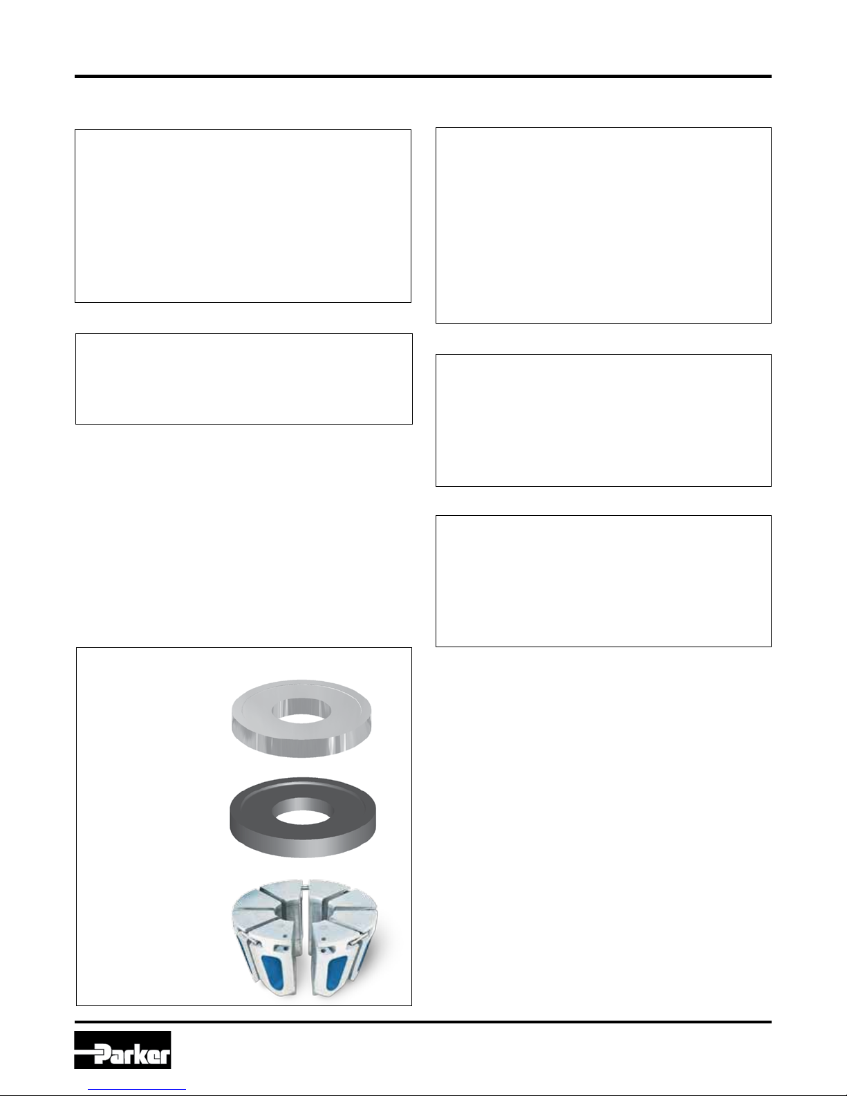
Karrykrimp
Bulletin 4480-T30-US
• Read the entire Technical Manual prior to mounting and operating this crimper.
• View the enclosed DVD prior to operating this crimper
WARNING — When using this machine, always exercise basic safety precautions, including but not limited to
the following:
1. Use this machine only for its intended purpose: to fabricate Parker hose assemblies.
2. Parker Hannifin will not accept responsibility for any incidental, consequential or special damages of any
kind or nature whatsoever that result from any subsequent alterations to any Parkrimp machine. Parker
Hannifin disclaims any warranties on items altered after leaving the Parker Hannifin facility.
3. This machine must be properly installed and located in accordance with the installation instructions
before it is used.
To minimize the possibility of injury:
1. The power unit must be connected to a grounded properly rated, protected and sized power-supply
circuit to prevent electrical shock and to avoid electrical overload;
2. Do not operate over maximum rated working pressure;
3. Check for safe system setups.
Make sure that the valve, connecting hoses, etc. are protected from any external source of damage, such as:
excessive heat, flame, moving machine parts, sharp edges, falling objects, corrosive chemicals, etc.
Copyright 2009, Parker Hannifin Corporation, All Rights Reserved
The items described in this document are hereby offered for sale by Parker Hannifin Corporation, its subsidiaries or its authorized distributors. This offer and its acceptance are governed
by the provisions stated in the “Offer of Sale”.
Offer of Sale
IMPORTANT SAFETY NOTICE
THIS INFORMATION IS INTENDED FOR USE BY INDIVIDUALS POSSESSING ADEQUATE BACKGROUNDS OF
ELECTRICAL, ELECTRONIC AND MECHANICAL EXPERIENCE. ANY ATTEMPT TO REPAIR THIS MACHINE MAY
RESULT IN PERSONAL INJURY AND PROPERTY DAMAGE.
THE MANUFACTURER OR SELLER CANNOT BE RESPONSIBLE FOR THE INTERPRETATION OF THIS
INFORMATION, NOR CAN IT ASSUME ANY LIABILITY IN CONNECTION WITH ITS USE.
DISCONNECT ANY POWER CORD BEFORE SERVICING
IMPORTANT - RECONNECT ALL GROUNDING DEVICES
Safety Notices
Before selecting or using any of these Products, it is important that you read and follow the instructions below. Only Hose from Parker’s Stratoflex Products Division is approved for in-flight
aerospace applications.
WARNING: Failure or improper selection or improper use of hose, tubing, assemblies, fittings, quick action couplings or related accessories ("Products") can
cause death, personal injury and property damage. Possible consequences of failure or improper selection or improper use of these Products include but are not
limited to:
• Fittings thrown off at high speed.
• High velocity fluid discharge.
• Explosion or burning of the conveyed fluid.
• Electrocution from high voltage electric power lines.
• Contact with suddenly moving or falling objects that are controlled by the conveyed
fluid.
• Injections by high-pressure fluid discharge.
• Dangerously whipping hose.
• Contact with conveyed fluids that may be hot, cold,toxic, or otherwise injurious.
• Sparking or explosion caused by static electricity buildup or other sources of electricity.
• Sparking or explosion while spraying paint or flammable liquids.
• Injuries resulting from inhalation, ingestion or exposure to fluids.
! Parker Safety Guide for Selecting and Using Hose, Tubing, Fittings and Related Accessories
Publication No. 4400-B.1
Revised: August 2007
www.comoso.com