PartySpace MAGMA User manual

MAGMA
SKU: GASHEAT - EAN 5404019850413
Partyspace bv - Potteriestraat 67 - 8980 Beselare - BELGIUM - Phone +32 (0)57 36 03 30 - Fax +32 (0)57 48 79 61 - BTW BE 0830 189 643


EN.......................................................................................................................................................................................................... 4 - 21
NL....................................................................................................................................................................................................... 22 - 39
FR.......................................................................................................................................................................................................40 - 57
DE ...................................................................................................................................................................................................... 58 - 75
INHOUD
CONTENT
CONTENU
INHALT

810 mm
460 mm
Reflector
Flame screen
Burner base
Air admittance fence
Gas valve controller
Base of control housing
Post
Tank housing
Post bracket
Stand
765 mm
2003 mm
2190 mm
4
EN

PLEASE READ THE FOLLOWING SAFETY RULES PRIOR TO USAGE OF THE HEATER.
FOR YOUR SAFETY
In case you smell gas:
1. Shut off the gas supply to the appliance.
2. Extinguish any open flame.
3. lf the smell continues, immediately call the emergency services or the fire department.
Do not store or use gasoline or other flammable vapors and liquids in the vicinity of this or any
other appliance.
An LP cylinder not connected for use shall not be stored in the close proximity of this or any
other appliance.
WARNING
• For outdoor use or use in properly ventilated areas.
• A properly ventilated area must have a minimum of 25 % of open surface area.
• The surface area is the sum of all wall surfaces.
lmproper installation, adjustment, alteration, service or maintenance can cause injury or
property damage. Read the installation, operating and maintenance instructions thoroughly
before installing or using this equipment.
READ THE INSTRUCTIONS BEFORE INSTALLATION AND USE.
• This appliance must be installed and the gas cylinder must be stored in accordance with the
regulations in force.
• Do not obstruct the ventilation holes of the cylinder housing.
• Do not move the appliance when in operation.
• Shut off the valve at the gas cylinder or the regulator before moving the appliance.
• The tubing or the flexible hose must be changed within the prescribed intervals.
• Use only the type of gas and the type of cylinder specified by the manufacturer.
• The gas tank used for this patio heater must meet the following requirements: 31.8 cm diameter x
58 cm height with 15 kg maximum capacity.
• In case of heavy winds, particular attention must be paid to tilting of the appliance.
IMPORTANT SAFETY MEASURES
GAS HEATER | MANUAL
5
EN

• The injector in this appliance is not removable and is assembled by the manufacturer. It is forbidden
to convert the injector from one gas pressure to another.
• Do not connect the gas cylinder directly to the appliance without a regulator. Only use the type of
gas and the type of cylinder specified in the instructions.
Only use a regulator (complies with EN16129:2013 and the national regulation) of the correct
pressure corresponding to the appliance category.
• Use a 30 mbar regulator for butane/propane of the category l3B/P(30).
• Use a 30 mbar regulator for butane of the category l3+(28-30/37).
• Use a 37 mbar regulator for propane of the category l3+(28-30/37).
• Use a 50 mbar regulator for butane/propane of the category l3B/P(50).
PLEASE READ THE FOLLOWING SAFETY GUIDELINES CAREFULLY BEFORE OPERATION.
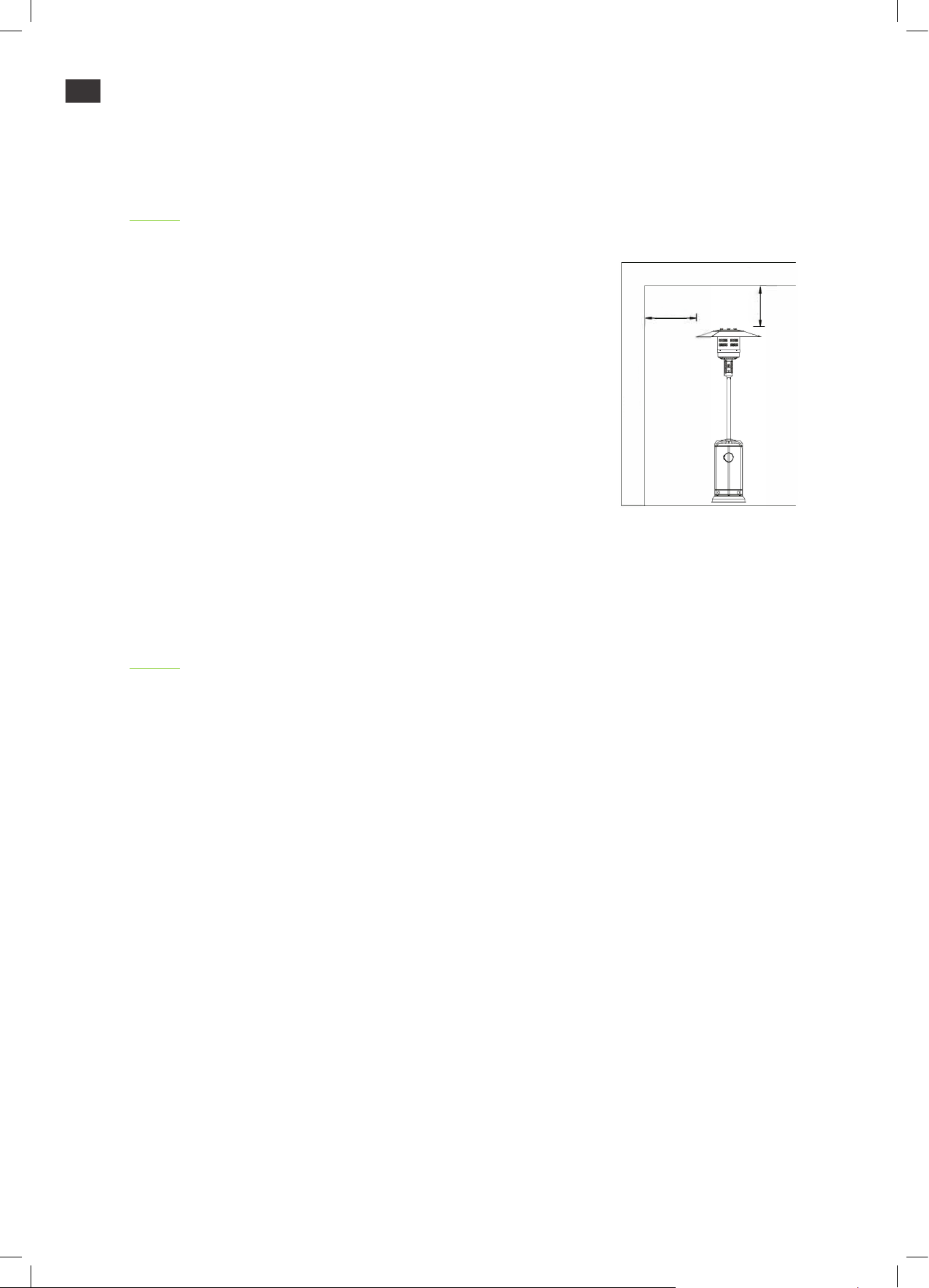
• Do not use the patio heater indoors as it may cause personal injury or property damage.
• This outdoor heater is not intended to be installed on recreational vehicles and/or boats.
• lnstallation and repair should be done by a qualified service person.
• lmproper installation, adjustment or alteration can cause personal injury or property damage.
• Do not attempt to alter the unit in any way.
• Never replace or substitute the regulator with any regulator other than the factory-suggested
replacement.
• Do not store or use gasoline or other flammable vapors or liquids in the heater unit.
• The entire gas system, hose, regulator, pilot and burner should be inspected for leaks and damage
before use, at least annually by a qualified service person.
• All leak tests should be done with a soap solution. Never use an open flame to check for leaks.
• Do not use the heater until all connections have been leak tested.
• Turn off the gas valve immediately if a gas smell is detected. Turn the cylinder valve OFF.
»lf the leak is at the hose/regulator connection: tighten the connection and perform another leak
test. lf bubbles continue to appear, the appliance should be returned to the manufactorer.
»lf the leak is at the regulator / cylinder valve connection: disconnect, reconnect, and perform
another leak test. lf bubbles continue to appear after several attempts, the cylinder valve is
broken and the appliance should be returned to the manufactorer.
• Do not transport the heater while in operation.
• Do not move the heater after it has been turned off until the temperature has cooled down.
• Keep the ventilation opening of the cylinder enclosure free and clear of debris.
• Do not paint the radiant screen, control panel or top canopy reflector.
• The control compartment, burner and circulation air passage ways of the heater must be kept
clean.
• Frequent cleaning is required.
• The gas tank should be turned off when the heater is not in use.
GAS HEATER | MANUAL
6
EN

• Check the heater immediately if any of the following occurs:
»The heater does not reach temperature.
»The burner makes popping noises during use (a slight noise is normal when the burner is
extinguished).
»There is a smell of gas in combination with extreme yellow tips of the burner flames.
• The gas regulator/hose assembly can not be located on places where people may trip over it or in
areas where the hose will not be subject to accidental damage.
• Any coverage or other protective device removed for servicing of the heater must be replaced
before operating the heater.
• Adults and children should stay away from high temperature surfaces to avoid burns or clothing
ignition.
• Children should be carefully supervised when they are close to the heater.
• Clothing or other flammable materials should not be hung or placed on or near the heater.
• Change the gas cylinder in a properly ventilated area. The appliance must be away from any ignition
source (candle, cigarettes, other flame producing appliances...).
• Check if the regulator seal is correctly fitted and able to fulfil its function.
• Do not obstruct the ventilation holes of the cylinder housing.
• Close the gas supply at the valve of the gas cylinder or the regulator after use.
• In case of gas leaks, the appliance can not be used.
• If on fire, the gas supply must be shut off and the appliance must be investigated and rectified
before it is used again.
• Check the hose at least once per month, each time the cylinder is changed, or before use after a
long period of inactivity.
• lf the hose shows signs of cracking, splitting or other deterioration, it must be replaced with a new
hose of the same length and quality.
• The use of this appliance in enclosed areas can be dangerous and is prohibited.
• Read the instructions before using this appliance. The appliance must be installed in accordance
with the instructions and local regulations.
GAS HEATER | MANUAL
7
EN

• The heater is for outdoor use only. Always ensure that
adequate fresh air ventilation is provided.
• Always maintain proper clearance to combustible materials,
at least 1 m from top and sides.
• The heater must be placed on level firm ground.
• Never operate the heater in an explosive atmosphere like in
areas where gasoline or other flammable liquids or vapors are
stored.
• The used pressure regulator and hose must be conform to the local standards.
• The installation must be conform to local standards, or in absence of those, with the standard for
the storage and handling of liquid petroleum gases.
• A dented, rusted or damaged gas tank may be hazardous and should be checked by your tank
supplier. Never use a gas tank with a damaged valve connection.
• The gas tank must be installed so that no gas can concentrate inside the operating cylinder.
• Never connect an unregulated gas tank to the heater.
HEATER STAND AND LOCATION
GAS REQUIREMENTS
GAS HEATER | MANUAL
Wall
Ceiling
100 cm
8
EN

Gas connections on the heater are leak tested at the factory prior to shipment. A complete
gas tightness check must be performed at the installation site due to possible mishandling in
shipment or excessive pressure being applied to the heater.
• Make a soap solution of one small part of liquid detergent and one part of water. The soap solution
can be applied with a spray bottle, brush or rag. Soap bubbles will appear in case of a leak.
• The heater must be checked with a full cylinder.
• Never perform a leak test while smoking.
1. Make sure the safety control valve is in the OFF position.
2. Turn the gas supply ON.
3. In case of a leak, turn off the gas supply.
4. Tighten any leaking connections, then turn the gas supply on and check again.
LEAK TEST
TO TURN ON THE HEATER
1. Turn on the valve on the gas supply cylinder completely.
2. Press and turn the variable control knob to PILOT position (counter-clockwise 90°).
3. Press the variable control knob and hold for 90 seconds. While holding down the variable
control knob, press the igniter button several times until the pilot flame lights. Release the
variable control knob after the pilot flame lights.
»lf a new tank has just been connected, please allow at least one minute for the air in the gas
pipeline to purge out through the pilot hole.
»When lighting the pilot flame, make sure that the variable control knob is continuously pressed
down while pressing the igniter button. The variable control knob can be released after the pilot
flame lights.
»The pilot flame can be watched and checked from the small round window with sliding lid
located at the bottom of the flame screen (to the left or right side of the controller).
»lf the pilot flame does not light or it goes out, repeat step 3.
4. After the pilot flame lights, turn the variable control knob completely open and leave it for
five minutes or more before turning the knob to the desired temperature position.
OPERATION AND STORAGE
GAS HEATER | MANUAL
9
EN

TO TURN OFF THE HEATER
1. Turn the variable control knob to PILOT position.
2. Press and turn the variable control knob to OFF position.
3. Turn off the valve on the gas supply cylinder completely.
STORAGE
1. Always close the gas valve of the gas cylinder after use or in case of a disturbance.
2. Remove the pressure controller and the hose.
3. Check the tightness of the gas valve and check if it is not damaged. lf you suspect a
damage, have it checked by your manufactorer.
4. Do not store liquid gas cylinders in a sub-terrain or at places without adequate
air ventilation.
GAS HEATER | MANUAL
• Wipe off combustible powder or coated corrosive surfaces with a soft, moist rag.
• Do not clean the heater with cleaners that are combustible or corrosive.
• Remove debris from the burner to keep it clean and safe for use.
• Cover the burner unit with the optional protective cover when the heater is not in use.
CLEANING AND CARE
Variable control knob
OFF: Turn off the heater
HI: Maximum temperature position
LO: Minimum temperature position
Igniter
10
EN

PARTS LIST
AReflector panel
BReflector plate
FF Reflector stud
CHead assembly
FGas hose
DCylinder housing
EPost
GSupport bracket
HBase
IWheel kit
TOOLS NEEDED
• Open end wrench 10 & 13 mm
• Adjustable opening wrench (2) 20 cm long
• Slip joint pliers 23 cm long
• Screwdriver
• Soap solution (for leak test)
GAS HEATER | MANUAL
11
EN

CONSTRUCTION AND CHARACTERISTICS
• Transportable terrace/garden heater with tank housing
• Casing in stainless steel
• Gas hose connections with metal clamp
SPECIFICATIONS
• For use with propane, butane or their mixtures only
• Max. wattage: 13 000 watts
• Min. wattage: 5 000 watts
• Consumption:
• Use the proper regulator according to the outlet pressure of the regulator as shown in the
table above.
APPLIANCE
CATEGORY I3+ (28 - 30 / 37) I3B/P (30) I3B/P (50) I3B/P (37)
TYPES OF GAS Butane Propane
Butane,
propane
or their
mixtures
Butane,
propane
or their
mixtures
Butane,
propane
or their
mixtures
GAS PRESSURE 28 - 30
mbar 37 mbar 30 mbar 50 mbar 37 mbar
OUTLET PRESSURE OF
REGULATOR 30 mbar 37 mbar 30 mbar 50 mbar 37 mbar
GAS HEATER | MANUAL
12
EN

GAS HEATER | MANUAL
TABLE OF INJECTORS
• The hose and regulator assembly must be conform to local standards.
• The regulator outlet pressure should meet the corresponding gas category in the table of injectors.
• The appliance requires an approved hose of 1.4 m.
APPLIANCE
CATEGORY I3+ (28 - 30 / 37) I3B/P (30) I3B/P (50) I3B/P (37)
TYPES OF GAS Butane Propane
Butane,
propane
or their
mixtures
Butane,
propane
or their
mixtures
Butane,
propane
or their
mixtures
GAS PRESSURE 28 - 30
mbar 37 mbar 30 mbar 50 mbar 37 mbar
TOTAL HEAT INPUT
(HS) : (QN) 13 kW (Butane: 945 g/h - Propane: 928 g/h)
INJECTOR SIZE 1,90 mm for main burner
0,18 mm for pilot burner
1,70 mm
for main
burner
0,18 mm for
pilot burner
1,80 mm
for main
burner
0,18 mm for
pilot burner
E.g.: The marking 1,90 on the injector indicates that the size of injector is 1,90 mm.
13
EN

ASSEMBLY PARTS
GAS HEATER | MANUAL
Nut
M8
Qty: 2
Screw
M6 x 8
Qty: 9
Bolt
M8 x 16
Qty: 5
Cap
nut
Qty: 9
Flange
nut M6
Qty: 6
Wing
nut
Qty: 3
Wrench
Qty: 1
Stainless
steel bolt
Qty: 4
Bolt
M6 x 16
Qty: 6
Reflector
spacer
Qty: 3
Washer
Ø 8
Qty: 6
14
EN

Step 1: Use two M8 x 16 screws to attach the
wheels to the base.
Step 2: Put the three post brackets on the base
as shown. Use three medium bolts (M8 x 16) to
join the post brackets and stand.
Step 3: Put the post on top of the post brackets.
Use six large bolts and flange nuts (M6) to
connect the post to the post brackets. Tighten
the bolts and nuts.
GAS HEATER | MANUAL
Post bracket
Post
Nut
Bolt
Stand
Bolt
15
EN

Step 4: Place the tank housing on the stand.
Step 5: Remove the four bolts from the burner.
Step 6: Put the gas hose through the post.
Step 7: Fix the burner unit to the post with
the four bolts you removed in step 5.
GAS HEATER | MANUAL
Tank housing
Bolt
16
EN

Step 8: Check if the connection of the vertical
post and the burner are assembled according
to the instructions and if all bolts and nuts are
tightened.
Step 9: Put three flat washers on the three
reflector spacers.
GAS HEATER | MANUAL
Reflector spacer
OPTIONAL STEP - TABLE ASSEMBLY
Attach the table connector (E) to the
table (D).
Turn the handle of the connector
clockwise.
Put the pole through the hole in the
middle of the table.
Turn the table clockwise to tighten it
and counter-clockwise to loosen it.
Note: If the table cannot be tightened,
turn the handle of the connector
counter-clockwise a little, then turn
the table clockwise to tighten.
Loosen
Tighten
17
EN

Step 10: Fasten the reflector with three flat
washers and wing nuts.
Step 11: Lift the tank housing and rest it on the
post plate.
Step 12: Connect the end of the gas hose to the
regulator.
Step 13: Connect the regulator to the gas tank
and tighten it with the adjustable wrench.
Step 14: Put the gas tank on the stand.
GAS HEATER | MANUAL
Wing nut
Regulator
Gas tank
Reflector
18
EN

GAS HEATER | MANUAL
PROBLEM PROBABLE CAUSE SOLUTION
The pilot doesn’t light. • The gas valve is OFF.
• The gas tank is empty.
• The opening is blocked.
• There is air in the supply system.
• The connections are loose.
• Turn the gas valve ON.
• Refill or replace the gas tank.
• Clean or replace the opening.
• Purge air from the supply
system.
• Check all the connections.
The pilot doesn’t stay
on.
• There is debris around the pilot.
• The connections are loose.
• The thermocouple is broken.
• There is a gas leak.
• The pressure is low because of a
nearly empty gas tank.
• Clean the dirty area.
• Tighten the connections.
• Replace the thermocouple.
• Check the connections.
• Refill or replace the gas tank.
The burner doesn’t
light.
• The pressure is low because of a
nearly empty gas tank.
• The opening is blocked.
• The control is not ON.
• The thermocouple is broken.
• The pilot light assembly is bent.
• The appliance is not in the
correct position.
• Refill or replace the gas tank.
• Remove or clean the opening.
• Turn the valve to ON.
• Replace the thermocouple.
• Place the pilot properly.
• Position the appliance properly
and retry.
TROUBLESHOOTING
19
EN

DISPOSAL
Waste electrical production should not be disposed of with household waste. Please recycle
were facilities exist. Check with your local authority or retailer for recycling advice.
If you wish to receive more information or need support, you can send an e-mail to
customer.service@partyspace.eu.
We grant you as a client/customer a warranty of two years for hidden defects in our products.
When this term has expired, we do not owe the client/customer any warranty for hidden
defects in our products anymore.
SUPPORT AND WARRANTY
20
EN GAS HEATER | MANUAL
This manual suits for next models
2
Table of contents
Languages:
Other PartySpace Patio Heater manuals
Popular Patio Heater manuals by other brands

Orbegozo
Orbegozo PHE 85 instruction manual

Blue Sky Outdoor Living
Blue Sky Outdoor Living WBPFP22 owner's manual

Spear & Jackson
Spear & Jackson ZQ446 Instruction

Gasmate
Gasmate NG1P45 Installation, operation and maintenance instructions

Suntec Wellness
Suntec Wellness Klimatronic Heat Patio 2000 Carbon manual

Sunwood
Sunwood MARINO manual