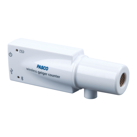
PASCO Wireless Smart Gate User manual

Reference Guide
013-16123A
Wireless Smart Gate
PS-3225
1The Swivel Rod Clamp can be detached
*See the PASCO catalog or the PASCO web site www.pasco.com for more information.
Legend
(1) Swivel Rod Clamp1(7) Emitter Port 2 (13) Super Pulley Tab
(2) Bluetooth LED (8) Photogate Tape Slot (14) USB Port
(3) Device ID (9) 1/4-20 Threaded Hole (15) (Port 4)Laser Detector Port
(4) Battery LED (10) Detector Port 1 (16) Indicator LED
(5) Power Button (11) Detector Port 2 (17) Micro USB Cable
(6)Emitter Port 1 (12) (Port 3) Auxiliary Port
Required Item* Model Number*
PASCO Data Collection Software see www.pasco.com
(1)
(1)
(2)
(3)
(4)
(5)
(6)(6)
(7)
(8)
(9)
(8) (10)
(11)
(12)
(13)
(14)
(15)
(16)
(16)
(17)
Power: Rechargeable Battery
Connection: USB or
Software: SPARKvue or
PASCO Capstone

PS-3225 Introduction
2
013-16123A
Compatible Equipment*
Initial Step: Connect to a USB Port or USB Charger
Use the included Micro USB Cable to connect the Micro USB Port on the Wireless Smart Gate to a
USB port or a USB charger (such as PS-2575A). When connected to a USB port or charger, the
Battery LED shines yellow to show the battery is charging. When the battery is charged, the Battery
LED shines green. Allow 3 hours for charging.
Introduction
The PASCO Wireless Smart Gate is a versatile measuring device that can connect to a computer or mobile device
wirelessly through Bluetooth (BLE) or physically with a Micro USB cable. It measures the time for an object’s
motion, such as a PASCO Cart, as the object blocks one or more beams of light. The Smart Gate has three
detector ports and one Auxiliary port. There are slots for Ports 1 and 2 for Photogate Tape (ME-6663) or Photogate
Tape, High Resolution (ME-6666).
Port 1 and Port 2 operate in the same way as a pair of PASCO Photogates that are side-by-side.The space
between the emitters for Port 1 and Port 2 is 1.5 cm. PASCO Capstone or SPARKvue software records and
displays the times for a variety of timing combinations such as the amount of time each port is blocked, or the time
from when one port is blocked until the second port is blocked. The software also displays the values of
calculations such as the speed or velocity between Port 1 and Port 2.
Port 3, the Auxiliary Port, is the port for a PASCO Photogate or similar device
such as a Time-of-Flight Accessory. The Auxiliary port accepts a 0.25 inch
(6.35 mm) “tip-ring-sleeve” phono plug.
Port 4, the Laser Detector Port, is designed to work with a laser beam to
allow measurement of an object too large to pass through the Wireless Smart Gate. The software begins recording
time when a laser beam shining into the port is blocked by a passing object.
Product Name Model Number
Super Pulley ME-9450A
Super Pulley with Mounting Rod ME-9499
Photogate Stand ME-9805
Picket Fence (Large) ME-9377A
Picket Fence (Smart Timer) ME-8933
Picket Fence (Cart) ME-9804
Photogate Bracket (Track) ME-9806
Photogate Mounting Bracket (Projectile Launcher) ME-6812A
Photogate Head ME-9498A
Accessory Photogate ME-9204B
Time-of-Flight Accessory ME-6810A
Photogate Tape, High Resolution ME-6666
Photogate Pendulum Set ME-8752
Tip - Ring - Sleeve Phono Plug
PS-3225 Hardware Set-Up
3
013-16123A
Data Collection Software
Measurements from the sensor are recorded and displayed using PASCO software such as SPARKvue or PASCO
Capstone. SPARKvue allows the sensor to work with a computer or a mobile device such as a tablet, datalogger,
or smart-phone when the sensor is connected. PASCO Capstone will work on a PC or Mac.
See the PASCO web site at www.pasco.com/software for help in selecting the right PASCO software and to check
for the latest versions.
ON/OFF and Sleep Information
To turn the sensor on, press and hold the Power Button until the Battery LED shines red for a moment, and then
release the Power Button. The Bluetooth LED will blink to indicate that the sensor is ready to be “paired” with a
device using the PASCO software.The sensor puts itself to sleep after one hour of inactivity if connected, and after
several minutes if not connected. To turn the sensor off, press and hold the Power Button for a moment until the
Battery LED shines red. Release the Power Button and the Bluetooth LED stops blinking.
Hardware Set-Up
Mounting the Wireless Smart Gate to a Pulley Mounting Rod
A Pulley Mounting Rod (SA-9343) fits the 1/4-20 threaded
hole that is on the side of the Wireless Smart Gate opposite
to the swivel rod clamp.
The swivel rod clamp and thumbscrew allows the Wireless
Smart Gate to be mounted on a 0.63 cm (1/4 in.) diameter
rod (such as the ME-9805 Photogate Stand).
The open space for the Wireless Smart Gate is 7.2 cm
(width) by 4.0 cm (depth). Remember, the Laser Detector
Port (Port 4) allows the measurement of the motion of
larger objects when used with a laser.
PASCO Capstone SPARKvue
•Mac OS X •Mac OS X
•Windows •Windows
•iOS
•Android
•Chromebook
1/4-20
threaded hole
Mounting
Rod
Tab for
Super Pulley
Depth =
4.0 cm
Width =
7.2 cm
Swivel Rod
Clamp
Port 4, Laser
Detector Port
Port 3, Auxiliary
Port

Wireless Smart Gate Hardware Set-Up
4013-16123A
Adding a Super Pulley to the Wireless Smart Gate
The tab on the Wireless Smart Gate housing provides a seat for
attaching a PASCO Super Pulley (ME-9450A) using a Pulley
Mounting Rod. When using a Super Pulley with the Wireless
Smart Gate, only Detector Port 1 (“gate 1”) will record state
changes caused by the rotating pulley.
Mounting the Wireless Smart Gate on a PASCO Track
The Wireless Smart Gate can be attached to the side of a
PASCO Track with a Photogate Bracket (ME-9806). Slide the
square nut on the Photogate Bracket into the T-slot of the side
of the PASCO track. Remove the swivel rod clamp from the
side of the Wireless Smart Gate (but save the swivel rod clamp
for later use).
Use the short thumbscrew from the Photogate Bracket
assembly to attach the Wireless Smart Gate to the Photogate
Bracket.
Note that half of the Wireless Smart Gate housing fits between
the “rails” on each edge of one side of the Photogate Bracket,
and the Wireless Smart Gate can be adjusted up or down. If you
wish to adjust the Photogate Bracket to an angle relative to the
PASCO track, mount the bracket on the track with the smooth
side of the bracket against the edge of the track. The small
thumbscrew will hold the Wireless Smart Gate in place against
the smooth side of the bracket. Both the Photogate Bracket and
the Wireless Smart Gate can then be set an any angle.
Mounting
Rod
(SA-9242)
Super Pulley
(ME-9450A)
Tab for Super
Pulley
T-slot
Square
Nut
Photogate
Bracket
(ME-9806)
PASCO
Track
Wireless
Smart Gate

PS-3225 Hardware Set-Up
5
013-16123A
Mounting the Wireless Smart Gate on a PASCO
Projectile Launcher
Use a Photogate Mounting Bracket (ME-6821A) to
attach the Wireless Smart Gate to a PASCO Projectile
Launcher (see the PASCO web site for more information
about launchers).
Clamp the PASCO Projectile Launcher in place. Mount
the Photogate Mounting Bracket to the T-slot of the
Projectile Launcher. Adjust the bracket so that the second
position on the bracket is aligned with the end of the
launcher. Remove the swivel rod clamp from the side of
the Wireless Smart Gate (but save the swivel rod clamp
for later use). Use one of the smaller thumbscrews from
the Photogate Mounting Bracket (ME-6821A) to attach
the Wireless Smart Gate to the Photogate Mounting
Bracket as shown.
Using the Wireless Smart Gate with the
Time-of-Flight Accessory
The PASCO Time-of-Flight Accessory (ME-6810A) is
designed for projectile motion experiments. The
Time-of-Flight Accessory can be used with a Wireless Smart
Gate mounted on a Projectile Launcher to measure the time of
a projectile’s motion from launch to landing. Connect the plug
from the Time-of-Flight Accessory into Port 3, the Auxiliary
Port on the back of the Wireless Smart Gate. The Wireless
Smart Gate measures the initial speed of the projectile and the
Time-of-Flight Accessory measures total travel time.
Using the Wireless Smart Gate with Photogate Tape
High Resolution Photogate Tape (ME-6666) fits through the
Photogate Tape Slot on the detector side of the Wireless Smart Gate.
The Photogate Tape is made of a flexible Mylar material that can be cut to any length, and is reusable. The tape is 30 m long
with 1cm spacing between bands (edge-to-edge). When the tape is threaded through the Photogate Tape Slot of the Wireless
Smart Gate, the student can measure position, velocity, and acceleration with a high degree of accuracy.
Wireless
Smart Gate
Projectile
Launcher
Base
Photogate
Mounting
Bracket
(ME-6821A)
Thumbscrew
Projectile Launcher
(ME-6800)
Smart Gate
Time-of-Flight
Accessory Pad
Smart Gate
ME-6666
Photogate
Tape Slot
Photogate Tape,
High Resolution

Wireless Smart Gate Hardware Set-Up
6013-16123A
Using the Wireless Smart Gate with a Picket Fence on a Cart
Mount a Five Pattern Picket Fence (ME-9804) or a Smart Timer Picket Fence (ME-8933) to the accessory tray of a PASCO
Cart (such as the ME-6950 PAScar). Use a Photogate Mounting Bracket (ME-9806) to mount the Wireless Smart Gate on the
side of a PASCO Track (such as the ME-6960 PAStrack). Adjust the height of the Smart Gate to match the level of the desired
flag pattern on the Picket Fence.
Using the Wireless Smart Gate with a Photogate Pendulum
Use a clamp (such as the ME-9506 Pendulum Clamp), a
support rod, and string (such as the SE-8050 Braided Physics
String) to hang a Photogate Pendulum as shown with the string
attached at two points on the Pendulum Clamp,
Use a Mounting Rod (SA-9242 or ME-9483) and a clamp (such
as the ME-9507 Multi-Clamp) to Mount the Wireless Smart
Gate so that the Photogate Pendulum interrupts the infrared
beam as it swings through the Wireless Smart Gate. For more
accurate results, arrange the pendulum so that it swings close to
the emitter side of the Wireless Smart Gate.
Photogate Bracket
(ME-9806)
PASCO Track
PASCO Cart
Picket Fence
(ME-8933)
Wireless Smart Gate
Mounting
Rod
Clamp
Base
Support
Rod
Pendulum
Clamp
(ME-9506)
String
Photogate
Pendulum
(ME-8752 Emitter
side

PS-3225 Software Setup
7
013-16123A
Software Setup
Software Help
•In Sparkvue, tap or click the Main Menu icon.
•In the menu, select “Help...” for information about
collecting, displaying, and analyzing data.
•In the window that opens is the address of the web page for Help.
Copy and paste the address into a web browser program to open
the Sparkvue User’s Guide web page.
.
•SPARKvue User’s Guide web page”
.
•In PASCO Capstone, select PASCO Capstone Help from the Help menu, or
press F1.
Main Menu icon
Select
SPARKvue “Help” Window

Wireless Smart Gate Software Setup
8013-16123A
Bluetooth and Battery LED Information
The Bluetooth LED (light-emitting diode) and the battery LED operate as follows:
Indicator LED Information
The Indicator LED on the top of the Wireless Smart Gate shines when the sensor is on and connected to the
software and an object blocks the infrared beam entering Port 1 or Port 2. The Indicator LED also shines when
a Photogate or a Time-of-Flight Apparatus is attached to the Auxiliary Port (Port 3) and the photogate beam is
blocked or a projectile hits the Time-of-Flight pad.
Laser Detector Port (Port 4) is a special case. The sensor must be on and Port 4 must be selected in the
PASCO Capstone data collection software. If a laser beam shines into Port 4, and the laser beam is blocked,
the Indicator LED shines red. If the laser beam is unblocked, the Indicator LED is clear.
Bluetooth LED Status Battery LED Status
Red blink Ready to pair Red blink Low power
Green blink Connected
Port Status LED Color Status LED Color
1 Blocked Amber Unblocked Clear
2 Blocked Green Unblocked Clear
1 & 2 Blocked Red Unblocked Clear
3 Blocked Red Unblocked Clear

PS-3225 Connect the Sensor Wirelessly via Bluetooth in SPARKvue
9
013-16123A
Connect the Sensor Wirelessly via Bluetooth in SPARKvue
1. Turn on the sensor and start SPARKvue.
•The “choose a path” window opens.
.
2. To “pair” the Wireless Smart Gate wirelessly to the computing device (e.g., computer or tablet), click or touch
“Sensor Data” in the “choose a path” window.
•The “Sensor Data Configuration” screen opens.
3. In the “Sensor Data Configuration screen”, look in the “Connected Devices” list. Touch or click to select the
correct address that matches the Device ID XXX-XXX number found on the Wireless Smart Gate.
•A message confirms that the sensor is being connected.
•Next, in the “Sensor Data Configuration” screen, “Wireless Smart Gate” appears in the “Select Measurement
for Templates” panel,
4. Click or Touch the “gear-shaped” Configuration Icon
•The “Assign SmartGate” screen is revealed.
Click or Touch
Click or Touch
the
Configuration
Icon

Wireless Smart Gate Assign SmartGate- Smart Gate Only
10 013-16123A
Assign SmartGate- Smart Gate Only
The three choices are:.
•“Smart Gate Only”
•“Smart Gate and Auxiliary Port”
•”Auxiliary Port Only”
Smart Gate Only
Click or touch the menu arrow for
“Smart Gate Only” to show the
various timer choices.
See the descriptions that follow.
1. Smart Gate Only - Smart
Gate Timer
•Click or touch “Smart Gate
Timer” and then click or touch
“OK” to accept the choice and
close the dialog.
•The “Select Measurements for
Templates” panel is revealed.
•The panel shows “Speed
Between Gates” as the default
choice.
•This measurement is based
on the time from when the first
Detector Port beam is blocked
until the second Detector Port
beam is blocked.
Click or Touch the Menu arrow
Assign SmartGate Choices
Smart Gate Only- Timer Choices
Click or Touch to select
Smart Gate Timer Measurements
Click or Touch “OK” to accept the choice

PS-3225 Assign SmartGate- Smart Gate Only
11
013-16123A
2. Smart Gate Only - Photogate and Pendulum
1. Click or touch “Photogate and Pendulum” and then click or touch “OK” to accept the choice and close the dia-
log. The “Edit Timer Properties:” panel is revealed.
•If the Pendulum Width needs to
be changed, highlight the default
value in the “Edit Timer
Properties:” panel and enter the
actual value.
2. Click or touch “OK” to accept the
change and close the panel.
•The “Select Measurements for Templates” panel is revealed.
•The panel shows “Period” and “Velocity” with
“Period” as the default choice. This
measurement gives the amount of time for one
full pendulum swing. It begins with the first
interruption of the infrared beam and ends with
the third interruption. The “Velocity”
measurement gives the speed and direction of
the pendulum based on the time between Detector Port 1 and Detector Port 2. Direction is based on which
Detector Port is interrupted first.
3. Smart Gate Only - Photogate and Picket Fence
1. Click or touch “Photogate and Picket Fence” to select it and then click or touch “OK” to accept the choice and
close the dialog.
•The “Edit Timer Properties”
panel is revealed. If the Flag
Spacing on the Picket Fence
needs to be changed, highlight
the default value in the panel and
enter the actual value.
2. Click or touch “OK” to accept the
change and close the dialog.
•The “Select Measurements for Templates” panel is revealed.
•The panel shows “Position”, “Velocity”. and
“Acceleration” with “Position” as the default
choice. This measurement gives the amount of
distance moved based on the “Flag Spacing” for
the Picket Fence. The “Velocity” measurement
gives the speed and direction of the Picket
Fence based on the time between Detector Port
1 and Detector Port 2. Direction is based on
which Detector Port is interrupted first. The
“Acceleration” measurement is based on the
“Change in Velocity” per unit of time.
Default Pendulum Width -
Change if necessary.
Default Pendulum Width -
Change if necessary.
Default Flag Spacing -
Change if necessary.
Photogate and Picket Fence Measurements

Wireless Smart Gate Assign SmartGate- Smart Gate Only
12 013-16123A
4. Smart Gate Only - Smart Pulley (Linear)
1. Click or touch “Smart Pulley (Linear)” to select it and then click or touch “OK” to accept the choice and close
the dialog.
•The Edit Timer Properties” panel
is revealed.
•If the Spoke Arc Length for the
Super Pulley needs to be
changed, highlight the default
value in the “Edit Timer
Properties:” panel and enter the
actual value.
•Note, the Super Pulley’s Outside Circumference is 16 cm or 0.16 m. The Super Pulley has ten spokes, so the
Spoke Arc Length is one-tenth of the circumference, or 0.016 m. However, the Super Pulley’s Groove
Circumference is 15 cm, or 0.015 m for the Spoke Arc Length. If the Super Pulley measures a linear distance
by rolling on the outer edge of the pulley, use 0.016 m as the Spoke Arc Length. However, if the Super Pulley
measures a linear distance traveled by a string or thread in its groove, use 0.015 m as the Spoke Arc Length.
2. Click or touch “OK” to accept the change and close the dialog.
•The “Select Measurements for Templates” panel is revealed.
•The panel shows “Position”, “Velocity”. and
“Acceleration” with “Position” as the default
choice. This measurement gives the amount of
distance moved based on the “Spoke Arc
Length” of the Super Pulley. The “Velocity”
measurement gives the speed and direction of
the Super Pulley based on the time between
Detector Port 1 and Detector Port 2. Direction is
based on which Detector Port is interrupted first. The “Acceleration” measurement is based on the “Change in
Velocity” per unit of time.
5. Smart Gate Only - Smart Pulley (Rotational)
1. Click or touch “Smart Pulley (Rotational)” and then click or touch “OK” to accept the choice and close the dia-
log. The Edit Timer Properties” panel is revealed.
•If the Spoke Angle Spacing on
the Super Pulley needs to be
changed, highlight the default
value in the “Edit Timer
Properties:” panel and enter the
actual value.
•Note, the Super Pulley’s Spoke
Angle Spacing is 36 degrees.
2. However, If a different pulley is used, highlight the default value and enter the value for the pulley’s Spoke
Angle Spacing.
3. Click or touch “OK” to accept the change and close the dialog.
•The “Select Measurements for Templates” panel is revealed.
Default Spoke Arc Length -
Change if necessary.
Default Spoke Spacing-
Change if necessary.

PS-3225 Assign SmartGate- Smart Gate Only
13
013-16123A
•The panel shows “Position”, “Velocity”. and
“Acceleration” with “Position” as the default
choice. This measurement gives the amount of
angular distance moved based on the “Spoke
Arc Length” of the Super Pulley. The “Velocity”
measurement gives the angular speed and
direction of the Super Pulley based on the time
between Detector Port 1 and Detector Port 2.
Direction is based on which Detector Port is interrupted first. The “Acceleration” measurement is based on the
“Change in Velocity” per unit of time.
6. Photogate Timing (One Photogate)
•This option assumes that a flag will be passed through the beam between Emitter Port 1 and Detector Port 1.
1. Click or touch “Photogate Timing (One Photogate)” to select it and then click or touch “OK” to accept the choice
and close the dialog.
•The “Edit Timer Properties”
panel is revealed. The “Flag
Length” default value is 0.025 m.
2. However, if the Length of the flag
you are using to interrupt the
Wireless Smart Gate is a
different length, highlight the
default value in the panel and
enter the flag’s actual value.
3. Click or touch “OK” to accept the change and close the dialog.
•The “Select Measurements for Templates” panel
is revealed.The panel shows “Time In Gate” and
“Velocity In Gate” with “Time In Gate” as the
default choice. This measurement gives the
amount of time that the Wireless Smart Gate
beam for Detector Port 1 was blocked. The
“Velocity In Gate” measurement gives the speed
and direction of the flag used to block the beam based on the Flag Length and the Time In Gate.
7. Digital Input
•This option assumes that a flag will be passed through the beam between Emitter Port 1 and Detector Port 1.
1. Click or touch “Digital Input” to select it and then click or touch “OK” to accept the choice and close the dialog.
•The “Select Measurements for Templates” panel
is revealed.
Default Flag Length-
Change if necessary.

Wireless Smart Gate Assign SmartGate- Smart Gate and Auxiliary Port
14 013-16123A
•The panel shows “Logic State”
as the only choice. The “Logic
State” is “0.00” if the gate is
unblocked and “1.00” if the gate
is blocked. The example Table
shows that this measurement
records the Logic State
(unblocked or blocked) and the
time when the Logic State
happened.
8. General Counting
•This option assumes that a flag
or object will be passed through
the beam between Emitter Port
1 and Detector Port 1.
1. Click or touch “General Count-
ing” to select it and then click or touch “OK” to accept the choice and close the dialog.
•The Edit Timer Properties:” panel shows the default “Count Time Interval” is 1 (one) second (s).
2. However, if you are using a
different amount of time for
counting, highlight the default
value in the “Edit Timer
Properties:” panel and enter the
actual value.
3. Click or touch “OK” to accept the
change and close the dialog.
•The “Select Measurements for Templates” panel
is revealed. The panel shows “Pulse Count” as
the default choice. This measurement gives the
number of times per “Count Time Interval” that
the Wireless Smart Gate beam for Detector Port
1 was blocked.
Assign SmartGate- Smart Gate and Auxiliary Port
1. Smart Gate and Auxiliary Port - Time of Flight Example
•The second choice for Assign Smart Gate Is “Smart
Gate and Auxiliary Port”.
• In the Hardware Setup section, see Mounting the
Wireless Smart Gate on a PASCO Projectile
Launcher.
1. Connect a Time-of-Flight Accessory Pad
(ME-6810A) to Port 3, the Auxiliary Port on the Wire-
less Smart Gate.
Default Flag Length-
Change if necessary.
Default Time Interval-
Change if necessary.
Smart Gate
Time-of-Flight
Accessory Pad

PS-3225 Assign SmartGate- Smart Gate and Auxiliary Port
15
013-16123A
2. Click or touch the menu arrow for
“Smart Gate and Auxiliary Port”
to show the various choices.
•Click or touch “Time of Flight” to
select that choice.
3. Click or touch “OK” to accept the
choice and close the dialog.
•The “Edit Timer Properties”
panel is revealed. In the “Edit
Timer Properties” panel, the
“Photogate Spacing” default value
is 0.1 m.
4. However, if you are using a Smart
Gate, then the “Photogate
Spacing” is 0.015 m. Highlight the
default value in the “Edit Timer
Properties:” panel and enter the actual value. Click or touch “OK” to accept the change and close the dialog.
•The “Select Measurements for Templates” panel
is revealed.
•The panel shows “Initial Velocity” and “Time of
Flight” with “Initial Velocity” as the default
choice. This measurement gives the velocity of
the projectile fired by the Projectile Launcher as
calculated based on the Photogate Spacing and the time from when the projectile blocked “Port 1” until it
blocked “Port 2”.
•The “Time Of Flight” measurement gives the time from when the projectile blocks “Port 1” of the Smart Gate
until the projectile hits the Time-Of-Flight Accessory pad.
Click or Touch the Menu arrow
Smart Gate and Auxiliary Port Choices
Click or Touch
Default value -
Change to 0.015 m for Smart Gate

Wireless Smart Gate Assign SmartGate- Smart Gate and Auxiliary Port
16 013-16123A
2. Smart Gate and Auxiliary Port - Collision Timer
One of the experiments for “Collision
Timer” is the “Impulse - Collision”
Experiment. In this experiment, a cart
on a slightly inclined track collides with
a force sensor and the impulse during
the collision is recorded. The cart’s
velocity just before the collision and
the velocity just after the collision are
measured by the Wireless Smart Gate.
The mass of the cart and the difference
in velocity (before and after) give the
change in momentum during the
collision. Is the impulse equal to the
change in momentum?
1. Click or touch “Collision Timer” and then click or touch “OK” to accept the choice and close the dialog.
•The “Edit Timer Properties” panel
is revealed.The “Flag Length”
default value may need to be
changed.
2. Measure the length of the “flag” or
the Picket Fence you are using.
Highlight the default value in the
“Edit Timer Properties:” panel and
enter the actual value. Click or touch “OK” to accept the change and close the dialog.
•The “Select Measurements for Templates” panel
is revealed. The panel shows “Velocity 1” and
“Velocity 2” with “Velocity 1” as the default
choice. This measurement gives the velocity of
the PASCO Cart as calculated based on the Flag
Length and the time from when the Flag blocked
“Detector Port 1” until it blocked “Detector Port
2”. Direction is determined based on which port
was blocked first. The “Velocity 2” measurement is the same and is designed to give the velocity of the cart
after it collides with the force sensor.
3. Click or touch the box next to “Velocity 2”.
Another experiment for Collision Timer is “Conservation of Momentum” (In an Explosion or a Collision).In an
“Explosion”, two carts, each with a picket fence (such as the ME-9804 Five Pattern Picket Fence) start at rest next
to each other in the middle of a track. Put the plunger of one cart at one of the three positions. Move the carts
together so that the end of the plunger on one cart touches the end of the other cart. Mount the Wireless Smart
Gate near one end of the track. Mount an Accessory Photogate near the other end of the track. Connect the
Accessory Photogate to Auxiliary Port (Port 3) on the Wireless Smart Gate. Start recording data and then release
the plunger so that the carts “explode” away from each other. The total momentum before the explosion is zero.
Use your data to determine whether the momentum is conserved.
Default value -
Change to your value.
Measurements for the Collision Timer

PS-3225 Assign SmartGate- Smart Gate and Auxiliary Port
17
013-16123A
In a “Collision”, the carts with magnetic bumpers start at opposite ends of the track, move toward each other, and
collide between the Accessory Photogate and Wireless Smart Gate. Start recording data and then push the two
carts toward each other so that they collide near the middle of the track. The magnetic bumpers force each cart to
rebound and pass through The Accessory Photoate and the Wireless Smart Gate again. Use your data to
determine whether the total momentum after the collision is equal to the total momentum before the collision.
3. Smart Gate and Auxiliary Port - Photogate Timing (Two Photogates)
The “Photogate Timing (Two Photogates)” is designed for experiments such as “Acceleration Down an Inclined
Plane”. In this experiment, a cart starts at the top of an inclined PASCO track. When released, the cart accelerates
down the track and its velocity is measured when it passes through the Wireless Smart Gate and again when it
passes through the second photogate. The second photogate should be a PASCO Photogate Head (ME-9498A) or
the PASCO Accessory Photogate (ME-9204B). Connect the plug from the second photogate into Port 3, the
Auxiliary Port on the back of the Wireless Smart Gate. In this mode, Detector Port 1 on the the Wireless Smart
Gate will make measurements and so will the second photogate.
Smart Gate
Photogate
Connection to Port 3,
the Auxiliary Port
Smart Gate
Photogate

Wireless Smart Gate Assign SmartGate- Auxiliary Port Only
18 013-16123A
1. Click or touch “Photogate Timing
(Two Photogates)” to select it and
then click or touch “OK” to accept
the change and close the dialog.
The “Edit Timer Properties” panel
is revealed. The “Flag Length”
default value may need to be
changed.
2. Measure the length of the “flag”
on the Picket Fence you are
using. Highlight the default value in the “Edit Timer Properties:” panel and enter the actual value.
3. Also, the “Photogate Spacing” default value may need to be changed. Measure the distance separating the
Wireless Smart Gate and the second photogate. Highlight the default value in the “Edit Timer Properties:”
panel and enter the actual value. Click or touch “OK” to accept the change and close the dialog. The “Select
Measurements for Templates” panel is revealed.
•The panel shows seven measurements with
“Time In Gate1” as the default choice. This
measurement gives the time that the flag of the
picket fence blocked Detector Port 1.
•“Velocity In Gate1” is the velocity of the cart
based on the flag length and the time that
Detector Port 1 was blocked.
•The “Time in Gate2” and “Velocity in Gate2” are
based on the flag length and the time that the
flag blocked the second photogate.
•The “Time Between Gates”, “Velocity Between
Gates”, and “Acceleration Between Gates” all depend on the Photogate Spacing distance and the time
between when the Wireless Smart Gate was blocked and the second photogate was blocked
Assign SmartGate- Auxiliary Port Only
The third choice for “Assign Smart
Gate” is
•”Auxiliary Port Only”
Auxiliary Port Only
Click or touch the menu arrow for
“Auxiliary Port Only” to show the
choice (Free Fall Adapter).
Go to www.pasco.com to see the
description of the ME-9207B Free
Fall Adapter.
Default value -
Change value if needed
Default value -
Change value if needed
Click or Touch the Menu arrow
Assign SmartGate Choices

PS-3225 Assign SmartGate- Auxiliary Port Only
19
013-16123A
1. Auxiliary Port Only - Free Fall Adapter
1. Connect the plug from the PASCO Free Fall Adapter to Port 3, the Auxiliary Port on the Wireless Smart Gate.
The Free Fall Adapter is designed to hold a metal ball at a height above the “receptor pad”. When the ball is
released, timing begins, When the ball hits the pad, timing stops. Use the instructions that come with the Free
Fall Adapter to set it up for measurement.
2. Click or touch “Free Fall Adapter”
and then click or touch “OK” to
accept the choice and close the
dialog. The “Edit Timer
Properties” panel opens.The
“Height Of Fall” default value is 1
m.
3. After you set up the Free Fall
Adapter, carefully measure the distance from the bottom of the ball to the top of the receptor pad. Highlight the
default value in the “Edit Timer Properties:” panel and enter your actual value. Click or touch “OK” to accept the
change and close the dialog.
•The “Select Measurements for Templates” panel is revealed.
•The panel shows “Time Of Fall” and
“acceleration,” with “Time Of Fall” as the default
choice. This measurement gives the time for the
ball to fall and “acceleration” is calculated based
on the “Time of Fall” and the “Height Of Fall”.
Auxiliary Port Only Timer Choice
Click or Touch
Click or Touch
ME-9207B Free Fall Adapter
Default value -
Change to your measured value
2
2
1
ygt
2
2y
g
t

Wireless Smart Gate Connect the Sensor Wirelessly in PASCO Capstone
20 013-16123A
Connect the Sensor
Wirelessly in PASCO
Capstone
1. Turn on the sensor and start the software. In the
PASCO Capstone Tools palette, click the “Hard-
ware Setup” icon to open the Hardware Setup
panel.
•If no device is connected, the panel says
“Searching for wireless devices…”. and, below
that, “Please connect to an interface or wireless
device.” The panel shows the “Available Wireless
Devices”.
2. Under “Available Wireless Devices,” click the
sensor that matches the XXX-XXX Device ID
number that is on one side of the Wireless Smart
Gate.
•A “Connecting to the sensor” message appears
briefly.
•The Hardware Setup panel changes to show the
image of the Wireless Smart Gate including Port 3,
the Auxiliary Port. and Port 4, the Laser Detector
Port.
•The default setup choice is “Smart Gate (Single
Flag)”.
Smart Gate (Single Flag) Setup
1. Click the “Hardware Setup” icon in the Tools pal-
ette to close the “Hardware Setup” panel.
2. Click the “Timer Setup” icon in the tools palette to
open the Timer Setup panel.
•The Timer Setup panel is revealed.
Click to select the
sensor
Device ID
Port 3, the
Auxiliary Port
Port 4, the Laser
Detector Port
Timer
Setup
Icon
Hardware Setup Icon
This manual suits for next models
1
Table of contents
Other PASCO Measuring Instrument manuals

PASCO
PASCO EM-3556 User manual

PASCO
PASCO ME-9495A User manual

PASCO
PASCO WA-7428 User manual

PASCO
PASCO PS-3215 Use and care manual

PASCO
PASCO PS-3223 User manual

PASCO
PASCO PS-3515 User manual

PASCO
PASCO OS-8458B User manual

PASCO
PASCO PS-2136A User manual

PASCO
PASCO Pasport PS-2152 User manual

PASCO
PASCO OS-8525A User manual

PASCO
PASCO PASPORT PS-2148 User manual

PASCO
PASCO SE-7611 User manual

PASCO
PASCO Pasport PS-2600 User manual

PASCO
PASCO PASPORT PS-2230 User manual

PASCO
PASCO Xplorer GLX Programming manual

PASCO
PASCO PS-3215 User manual

PASCO
PASCO OS-8516A User manual

PASCO
PASCO ME-9837 User manual

PASCO
PASCO PS-3518 User manual

PASCO
PASCO PS-3321 User manual