manuals.online logo
Brands
  1. Home
  2. •
  3. Brands
  4. •
  5. Paser
  6. •
  7. Automobile Accessories
  8. •
  9. Paser SLIMKEY OBD User manual

Paser SLIMKEY OBD User manual

PROCEDURE TO SET IMPULSES
If you need to set the output different from the default you need to run the operation described
below:
1. Press and hold the button on the module until the green LED turns off and the LED blinks once
red.
2. Release the button, the LED of the module will blink one time Yellow followed by a Green blink
and one pause. This visualizing means that it is possible to change the positive output (PINK) as
described in the table attached.
3. Now each time we press the button of the module the Green flashes of the LED will increase
so verify the position number of the desired function listed in the table attached.
4. To confirm your choice, press and hold the button until the LED goes out.
PULSANTE
LED
PULSANTE
LED
PULSANTE
LED
PULSANTE
LED
PULSANTE
LED
TROUBLESHOOTING
The unit doesn’t carry out any function and the LED is off.
Verify the connections of the power supply.
The correctly powered unit doesn’t carry out any function and the LED is off.
Verify the CANBUS connections.
The unit is connected correctly and the RED LED flashes.
The unit hasn’t been able to synchronize with the CANBUS, turn on the key.
The unit is connected correctly and the RED LED flashes and key is turned on.
The unit has carried out the synchronization with the CANBUS but hasn’t been able to identify the vehicle, contact
Paser.
TECHNICAL CHARACTERISTICS
POWER SUPPLY 10/16 VDC
SLEEP MODE COMSUMPTION 1 mA
WORKING MODE COMSUMPTION 1 A
MAX CURRENT OUTPUT 1.5 A
PULSANTE
LED
PULSANTE
LED
PULSANTE
LED
5. Release the button, the LED of the module will blink 2 times Yellow followed by a Green blink
and one pause. This visualizing means that it is possible to change the speedpulse output
(GREY) as described in the table attached.
6. Now each time we press the button of the module the Green flashes of the LED will increase
so verify the position number of the desired function listed in the table attached.
7. To confirm your choice, press and hold the button until the LED goes out.
THIS PRODUCT IS GUARANTEED FOR 2 YEARS FOR ANY MANUFACTURING DEFECTS.
THE FISCAL DOCUMENT SERVES AS THE GUARANTEE VALIDITY
The information in this guide and in its attaches are purely for information purposes, therefore, are subject to change without
notice. At the time of publication the information is correct and reliable. However Paser can not be held responsible for any
consequences resulting from errors, omissions or incongruence in this manual (for ex. according to missed audio configuration
back-up of the vehicles). Paser reserves the right to improve / change the product or manual without obligation to notify users.
CF0006OB2O12 SLIMKEY OBD
REV. 1.16
CAVI
ROSSO A POSITIVO 12 V
NERO A GND
ROSA USCITA POSITIVA
(DEFAULT: POSITIVO SOTTOCHIAVE)
VERDE CAN H
BIANCO CAN L
GRIGIO USCITA ODOMETRICA
(DEFAULT: 4000 IMPULSI PER MIGLIO)
ARANCIO NON USATO
INSTALLAZIONE
SLIMKEY OBD è stato progettato per risolvere in modo definitivo la problematica del segnale
odometrico sui veicoli con sistemi CANBUS.
Questo è reso possibile dal nuovo modulo SLIMKEY OBD che collegato alla linea CANBUS della
presa OBD fornirà in pochi secondi il segnale di velocità.
Il modulo può fornire simultaneamente due uscite personalizzabili: una uscita positiva e una
odometrica.
La compatibilità è testata su veicoli con presa OBDII e con protocollo SAE-J2284 o ISO 15765.
Per eventuale assistenza contattare il numero di supporto tecnico 0141- 947676.
CONNESSIONI A PRESA OBD
SLIMKEY OBD si collega sulla presa OBD come da diagramma sotto che si riferisce alle connes-
sioni standardizzate dal protocollo SAE-J2284 o ISO 15765 .
La compatibilità si estende a tutti i veicoli dal 2001 per motorizzazioni a benzina e dal 2004 per
motorizzazioni diesel.
Connettore OBD visto dal lato di uscita dei fili:
8
16
1
9
POSIZIONI OBD
16 POSITIVO 12 V
4 GND
5 GND
6 CAN H
14 CAN L
ATTENZIONE
Il positivo sottochiave generato dall’interfaccia è calcolato secondo le informazioni disponibili
sulla porta OBD del veicolo e pertanto potrebbe non essere fedele alla posizione della chiave.
L’uscita rimane attiva fin tanto che sarà presente il segnale can bus, per questo motivo il
positivo potrebbe essere presente per diversi minuti dopo la rimozione della
chiave.
CARATTERISTICHE TECNICHE
ALIMENTAZIONE 10/16 VDC
ASSORBIMENTO A RIPOSO <1 mA
ASSORBIMENTO DURANTE IL FUNZIONAMENTO <100 mA in assenza di carico
MASSIMA CORRENTE IN USCITA 1.5 A
ANOMALIE
L’unità non esegue alcuna funzione ed il LED è spento.
Verificare le connessioni di alimentazione.
L’unità correttamente alimentata non esegue alcuna funzione ed il LED è spento.
Verificare le connessioni CANBUS.
L’unità è connessa correttamente ed il LED è acceso ROSSO.
L’unità ha eseguito la sincronizzazione con il CANBUS ma non ha individuato la vettura, accendere il
quadro strumenti.
L’unità è connessa correttamente, il LED è acceso ROSSO e il quadro strumenti è acceso.
L’unità ha eseguito la sincronizzazione con il CANBUS ma non ha individuato la vettura, contattare Paser.
PROCEDURA DI CONFIGURAZIONE USCITE
Qualora fosse necessario variare la configurazione di default del modulo è necessario eseguire
l’operazione sotto descritta:
1. Premere e tenere premuto il pulsante del modulo fino a che il LED verde si spenga ed il led
lampeggi una volta rosso.
PULSANTE
LED
2. Rilasciando il pulsante, il led del modulo esegue un lampeggio Giallo seguito da un lampeggio
Verde ed una pausa. Questa visualizzazione indica che è possibile variare l’uscita positiva
(ROSA) secondo la tabella allegata.
3. Ora ad ogni pressione del pulsante del modulo i lampeggi Verdi incrementano di numero,
individuare il numero di lampeggi secondo la funzione desiderata come descritto nella tabella
allegata.
4. Per confermare la scelta premere e tenere premuto il pulsante fino a che il led non si spegne.
PULSANTE
LED
PULSANTE
LED
PULSANTE
LED
PULSANTE
LED
5. Rilasciando il pulsante, il led del modulo esegue due lampeggi Gialli seguito da un lampeggio
Verde ed una pausa. Questa visualizzazione indica che è possibile variare la seconda uscita
(GRIGIO) secondo la tabella allegata.
6. Ora ad ogni pressione del pulsante del modulo i lampeggi Verdi incrementano di numero,
individuare il numero di lampeggi secondo la funzione desiderata come descritto nella tabella
allegata.
7. Per confermare la scelta premere e tenere premuto il pulsante fino a che il led non si spegne,
quindi rilasciare il pulsante il led si accenderà fisso.
PULSANTE
LED
PULSANTE
LED
PULSANTE
LED
QUESTO PRODOTTO HA 2 ANNI DI GARANZIA PER QUALSIASI DIFETTO DI FABBRICAZIONE RISCONTRATO.
COME VALIDAZIONE DELLA GARANZIA E’ NECESSARIA LA FATTURA DI ACQUISTO.
Le informazioni riportate in questo manuale e nei suoi allegati sono puramente a scopo informativo pertanto possono subire modifiche senza preavviso.
Al momento della pubblicazione le informazioni risultano corrette ed attendibili tuttavia Paser non può essere ritenuta responsabile per eventuali
conseguenze derivanti da errori, omissioni o incongruenze del presente manuale e dei suoi allegati (ad. es. per l’eventuale mancato ricupero di
configurazioni audio originali dei veicoli). Paser si riserva il diritto di migliorare/modificare il prodotto o il manuale senza l’obbligo di notifica agli utenti
CF0006OB2O12 SLIMKEY OBD
REV. 1.16
WIRE
RED TO POSITIVE 12 V
BLACK TO GND
PINK POSITIVE OUTPUT
(DEFAULT: POSITIVE IGNITION)
GREEN CAN H
WHITE CAN L
GREY SPEED PULSE OUTPUT
(DEFAULT: 4000 PULSES PER MILE)
ORANGE NOT USED
INSTALLATION
SLIMKEY OBD is designed to permanently solve the problem of the speedometer sensor on
vehicles with CAN BUS systems.
This is made possible using the new module SLIMKEY OBD, connected to the line CANBUS
OBD socket, it will provide in a few seconds the speed signal.
SLIMKEY OBD supplies 2 customizable outputs: a positive output and a speedpulse output.
Compatibility is tested on vehicles with OBDII port and protocol SAE-J2284 or ISO 15765.
To have support please call you supplier.
CONNECTIONS SETTING OBD
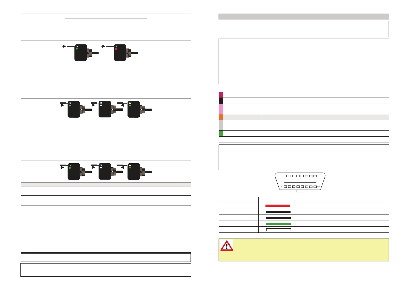
SLIMKEY OBD plugs into the OBD socket as per the diagram below, which refers to connections
standardized by protocol SAE-J2284 and ISO 15765.
Compatibility is extended to all vehicles from 2001 for petrol cars and from 2004 for diesel cars.
OBD connector viewed from the output side of the wires
8
16
1
9
OBD POSITION
16 POSITIVE 12 V
4 GND
5 GND
6 CAN H
14 CAN L
WARNING
Positive ignition output generated by interface is based on information available on car OBD
port and could be not relative to key position.
The output is active as long as canbus signal is available, for this reason output could be
active for some minutes after that key was removed.

This manual suits for next models

1

Other Paser Automobile Accessories manuals

Paser UNICOM EVO JVC User manual

Paser

Paser UNICOM EVO JVC User manual

Paser SKT 170 HYUNDAI User manual

Paser

Paser SKT 170 HYUNDAI User manual

Paser CF0026UNPS51 User manual

Paser

Paser CF0026UNPS51 User manual

Paser UNICOM EVO PLUS User manual

Paser

Paser UNICOM EVO PLUS User manual

Paser UNICOM JVC User manual

Paser

Paser UNICOM JVC User manual

Paser uDAB User manual

Paser

Paser uDAB User manual

Paser UNICOM/HUMMER H2 User manual

Paser

Paser UNICOM/HUMMER H2 User manual

Paser CONVERSO DISPLAY Reference manual

Paser

Paser CONVERSO DISPLAY Reference manual

Paser PARKVIEW CF0006UNPS41 User manual

Paser

Paser PARKVIEW CF0006UNPS41 User manual

Paser UNICOM CF0012UNPI21 User manual

Paser

Paser UNICOM CF0012UNPI21 User manual

Paser UNICOM ALPINE User manual

Paser

Paser UNICOM ALPINE User manual

Paser UNICOM CF0012UNKE21 User manual

Paser

Paser UNICOM CF0012UNKE21 User manual

Paser CONVERSO MUTE Reference manual

Paser

Paser CONVERSO MUTE Reference manual

Paser UNICO DUAL PLUS User manual

Paser

Paser UNICO DUAL PLUS User manual

Paser UNIKA User manual

Paser

Paser UNIKA User manual

Paser UNICOM SONY User manual

Paser

Paser UNICOM SONY User manual

Paser uDAB User manual

Paser

Paser uDAB User manual

Paser KIT052USSU12 User manual

Paser

Paser KIT052USSU12 User manual

Popular Automobile Accessories manuals by other brands

Magneti Marelli AC161 Installation instruction

Magneti Marelli

Magneti Marelli AC161 Installation instruction

FDI uEZ GUI Start here

FDI

FDI uEZ GUI Start here

JCROffroad JT Install instructions

JCROffroad

JCROffroad JT Install instructions

Rostra VOXXElectronics 250-1930 owner's guide

Rostra

Rostra VOXXElectronics 250-1930 owner's guide

TOP VEHICLE TECH GR3FORD5 installation manual

TOP VEHICLE TECH

TOP VEHICLE TECH GR3FORD5 installation manual

Safe Fleet PRIME DESIGN AR-2000-BLK manual

Safe Fleet

Safe Fleet PRIME DESIGN AR-2000-BLK manual

Skoda Fabia Combi 5J Fitting instructions

Skoda

Skoda Fabia Combi 5J Fitting instructions

Camcar 40077 Al Mounting instructions

Camcar

Camcar 40077 Al Mounting instructions

Camcar 40089 AL Mounting instructions

Camcar

Camcar 40089 AL Mounting instructions

Impac Tradesman 2000 installation manual

Impac

Impac Tradesman 2000 installation manual

DVB OFFROAD BRSB-01 installation manual

DVB

DVB OFFROAD BRSB-01 installation manual

Safari Snorkel SS385HF installation guide

Safari Snorkel

Safari Snorkel SS385HF installation guide

ULTIMATE SPEED 279746 Assembly and Safety Advice

ULTIMATE SPEED

ULTIMATE SPEED 279746 Assembly and Safety Advice

SSV Works DF-F65 manual

SSV Works

SSV Works DF-F65 manual

ULTIMATE SPEED CARBON Assembly and Safety Advice

ULTIMATE SPEED

ULTIMATE SPEED CARBON Assembly and Safety Advice

Witter F174 Fitting instructions

Witter

Witter F174 Fitting instructions

WeatherTech No-Drill installation instructions

WeatherTech

WeatherTech No-Drill installation instructions

TAUBENREUTHER 1-336050 Installation instruction

TAUBENREUTHER

TAUBENREUTHER 1-336050 Installation instruction

manuals.online logo
manuals.online logoBrands
  • About & Mission
  • Contact us
  • Privacy Policy
  • Terms and Conditions

Copyright 2025 Manuals.Online. All Rights Reserved.