C45/12V-EN
2
INSTALLAZIONE
Una volta estratto il diusore dalla confezione, per l’installazione
operare come segue:
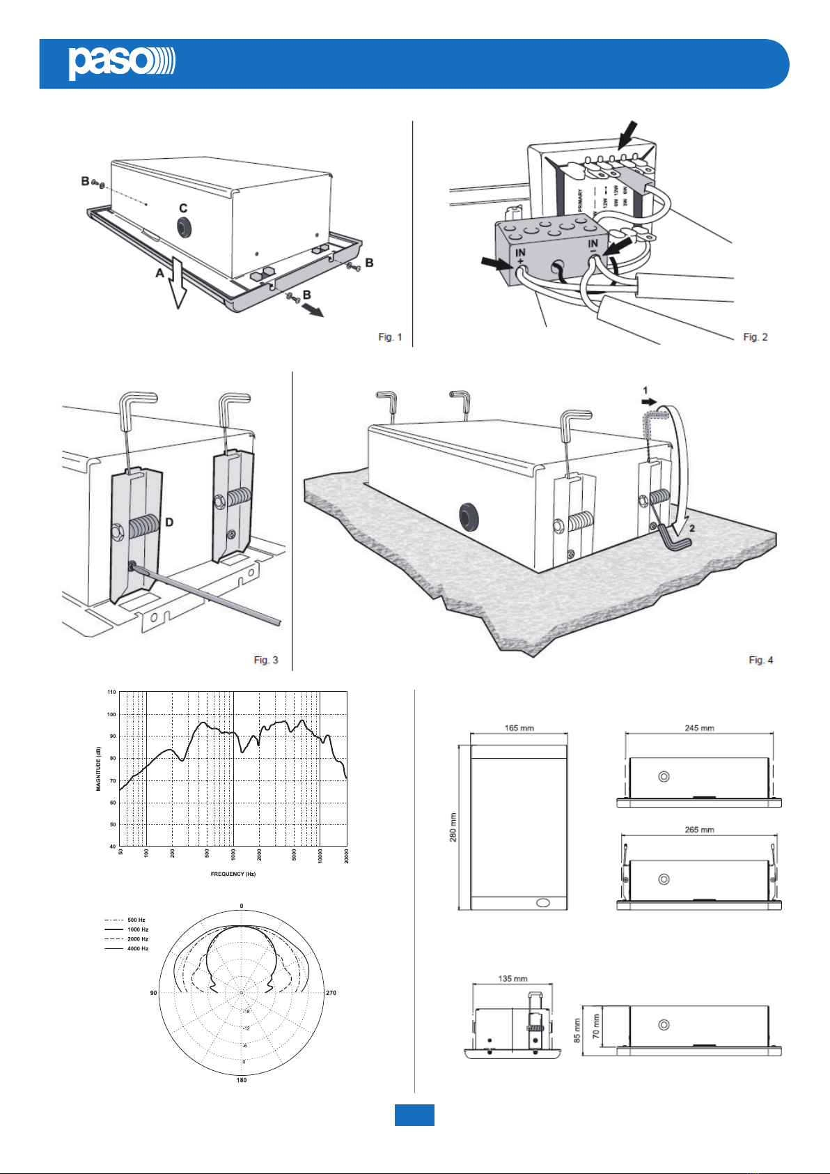
• Sganciare la griglia frontale (A) rimuovendo le tre viti autolettanti
che la ssano alla scatola da incasso utilizzando una chiave torx
a L TX20 (g. 1);
• Aiutandosi con un cacciavite, praticare un foro passante nei
passacavo (C) presenti sui lati della scatola.
• Realizzare, facendo riferimento alle “Dime di foratura”, il foro
relativo alla tipologia di incasso desiderata. A questo punto, è
necessario operare in relazione alla tipologia di montaggio.
Montaggio a parete:
• Inserire i cavi provenienti dalla linea di distribuzione nei passaca-
vo e collegarne le terminazioni alla morsettiera posta sulla griglia
frontale, facendo riferimento alle indicazioni riportate nella g. 2;
• Inserire la scatola da incasso nel foro praticato sulla parete;
• Applicare la griglia frontale e ssarla alla scatola utilizzando le tre
viti autolettanti (B) precedentemente rimosse.
Montaggio a controsotto*
• Fissare saldamente ai lati della scatola le stae con molle (D)
utilizzando le apposite viti e rondelle fornite in dotazione (g. 3);
• Inserire la scatola da incasso nel foro praticato sul pannello da
controsotto e sganciare le molle dalla loro sede in maniera
tale che, scattando verso il basso, vadano in battuta al pannello
bloccando così la scatola (g. 4);
• Inserire i cavi provenienti dalla linea nei passacavo, lasciando
un’adeguata ricchezza per eettuare il cablaggio;
• Posizionare il pannello nel controsotto;
• Collegare le terminazioni dei cavi alla morsettiera presente sulla
griglia frontale ed applicarla alla scatola utilizzando le tre viti
autolettanti (B) precedentemente rimosse.
* È opportuno eseguire queste operazioni con il pannello da
controsotto appoggiato su un piano.
CONNESSIONI
I diusori C45/12V-EN devono essere collegati in derivazione alla
linea di distribuzione, assicurandosi che la potenza complessiva
assorbita dai diusori non ecceda quella massima fornita
dall’amplicatore.
La potenza dei diusori è impostata in fabbrica per linea 100V/12W.
Nel caso si volesse modicare questa impostazione, è possibile
cambiare la potenza di uscita tramite l’apposito terminale ad
inserzione rapida facendo riferimento alla targhetta posta sul
trasformatore (vedi g. 2).
INSTALLATION
Once the speaker has been removed from its packaging, proceed
as follows:
• Unhook the front grille (A) removing the three self-tapping screws
(B) that secure it to the us-mounting box by means of L-shaped
TX20 torx key (g. 1);
• With the help of a screwdriver, make a through hole in each cble
gland (C) on the sides of the box.
• Using the drilling templates as a reference, make the
appropriatehole for te type of mounting required. At this point,
proceed as follows:
Wall-mounting:
• Pass the cables coming from the distribution system through the
cable gland and connect the ends to the terminal strip on the front
grille, following the instructions provided in g. 2;
• Fit the box for ush-mounting into the hole made for it in the wall;
• Fit the front grille and ecure it to the box using the three self-
tapping screws (B) that were removed earlier.
Mounting in a false ceiling*
• Fix the brackets with springs (D) rmly to the sides of the box,
using the screws and washers provided for this purpose (g. 3);
• Fit the box for us-mounting into te hole made in the false ceiling
panel and unhook the springs from their husings so that they
snap downwards and come to rest against the panel, thus locking
the box into place (g. 4);
• Pass the cables coming from the distribution line trough the cable
glands, leaving a suitable length for the wiring;
• Put the panel into place in the false ceiling;
• Connect the cable ends to the terminal strip on the front grille
and secure it to the box using the three self-tapping screws (B)
removed earlier.
* It is advisable to carry out these operations with the panel of the
false ceiling resting on a supporting surface.
CONNECTIONS
C45/12V-EN speaker units must be connected to the distribution line
by branching them, making sure that the overall output absorbed by
the speaker units does not exceed the maximum outout supplied by
the amplier.
The power of the speaker units is factory-set for a 100V/12W line.
If you wish to change this setting, it is possible to alter the output
power by means of the quick-t terminal provided for this purpose,
consulting the data plate on the transformer (see g. 2).