IM30
POS TERMINAL
•Increase the separation between the equipment and
receiver.
•Connect the equipment into an outlet on a circuit
different from that to which the receiver is connected.
•Consult the dealer or an experienced radio/TV
technician for help.
Caution
Any changes or modifications not expressly approved by
the manufacturer could void the user's authority to
operate this equipment.
Radiation Exposure
This device complies with FCC radiation exposure limits
for general environments.
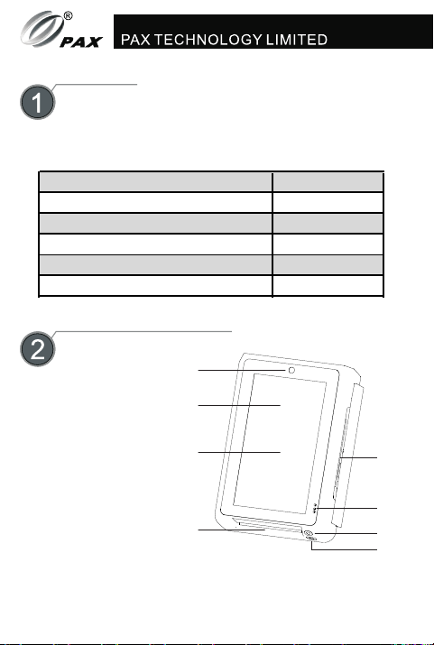
do not throw away, requires professional recycling
Class II equipment
for indoor use only
VI energy efficiency marking (level VI)
DC voltage
Index of Icons
7
~AC voltage
Responsible Party: PAX Technology Inc.
Address: 8880 Freedom Crossing Trail, Building 400, 3rd Floor,
Suite 300, Jacksonville, Florida 32256
T: 1-877-859-0099
P/N: 200312000000437
PAX TECHNOLOGY LIMITED reserves
the right to change product specifications
without prior notification.
Quick Setup Guide
78 9 10
Compliance Statements
FCC COMPLIANCE STATEMENT
This device complies with Part 15 of the FCC Rules.
Operation is subject to the following two conditions:
•Reorient or relocate the receiving antenna.
Warning
This equipment has been tested and found to comply with
the limits for a Class B digital device, pursuant to Part 15
of the FCC Rules. These limits are designed to provide
reasonable protection against harmful interference in a
residential installation.
This equipment generates, uses and can radiate radio
frequency energy and, if not installed and used in
accordance with the instructions, may cause harmful
interference to radio communications.
However, there is no guarantee that interference will not
occur in a particular installation. If this equipment does
cause harmful interference to radio or television
reception, which can be determined by turning the
equipment off and on, the user is encouraged to try to
correct the interference by one of the following measures:
This device complies with Industry Canada license-exempt
RSS standard(s).Operation is subject to the following two
conditions:
INDUSTRY CANADA STATEMENT
this device may not cause interference, and
Le présent appareil est conforme aux CNR d'Industrie
Canada applicables aux appareils radio exempts de
licence. L'exploitation est autorisée aux deux conditions
suivantes:
1)
2) this device must accept any interference, including
interference that may cause undesired operation of
the device.
l'appareil ne doit pas produire de brouillage, et
1)
2) l'utilisateur de l'appareil doit accepter tout brouillage
radioélectrique subi, même si le brouillage est
susceptible d'en compromettre le fonctionnement.
this device may not cause harmful interference, and
This device and its antenna(s) must not be co-located or
operating in conjunction with any other antenna or
transmitter, except tested built-in radios.
Cet appareil et son antenne ne doivent pas être situés ou
fonctionner en conjonction avec une autre antenne ou un
autre émetteur, exception faites des radios intégrées qui
ont été testées.
The Country Code Selection feature is disabled for
products marketed in the US/Canada.
La fonction de sélection de l’indicatif du pays est
désactivée pour les produits commercialisés aux États-
Unis et au Canada.
this device must accept any interference received,
including interference that may cause undesired
operation.
1)
2)
Radiation Exposure Statement
This equipment complies with IC radiation exposure limits
set forth for an uncontrolled environment. This
equipment should be installed and operated with
minimum distance 20cm between the radiator & your
body.
Cet équipement est conforme aux limites d'exposition
aux rayonnements IC établies pour un environnement
non contrôlé. Cet équipement doit être installé et utilisé
avec un minimum de 20 cm de distance entre la source
de rayonnement et votre corps.
Déclaration d'exposition aux radiations:
Manufacturer: PAX Computer Technology (Shenzhen) Co., Ltd.
Address: 4FL, Building #3, Software Park, 2nd Central Science-
Tech RD, High-Tech Industrial Park, Shenzhen, Guangdong, PRC
T: 0755-86169630 F: 0755-86169634
W: http://www.pax.com.cn