PBZ CropCare ATV-BASE User manual

by PBZ
25 Gallon ATV Sprayer
Model ATV-BASE
Form: ATV-BASEOM
Revision B.1 Rev. Date 04/19
Manufactured by PBZ LLC
A Paul B Zimmerman Inc. Company
www.CropCareEquipment.com
Owner's Manual


3
Table Of Contents
Identication of Machine ...................................................................... 3
Specications............................................................................................. 3
Before You Begin....................................................................................... 4
Safety Precautions.................................................................................... 4
General Guidelines........................................................................ 4
Before Operation ........................................................................... 5
During Operation .......................................................................... 5
Following Operation .................................................................... 5
Pump Safety Precautions............................................................ 5
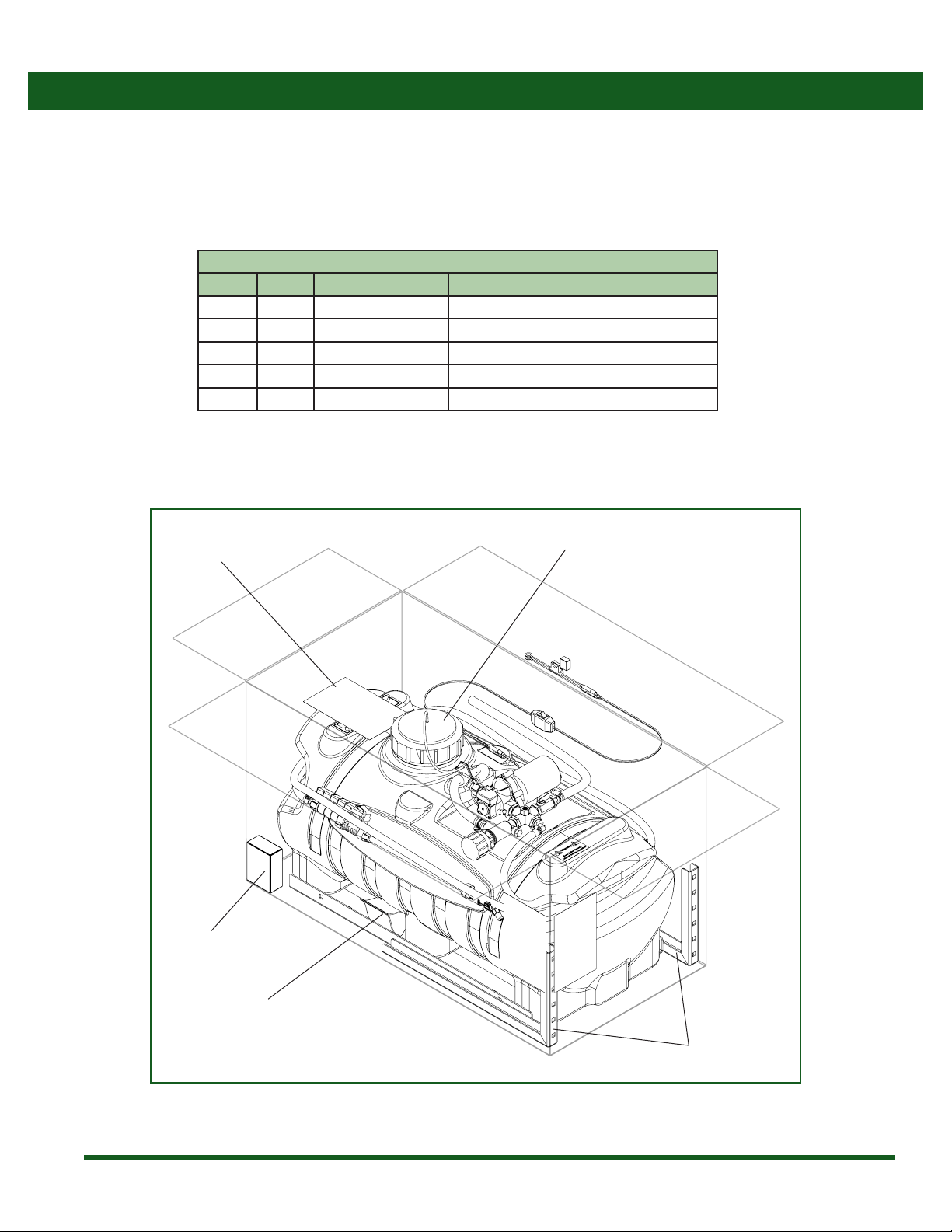
ATV-BASE Kit Contents ........................................................................... 6
ATV-BASE Box.................................................................................. 6
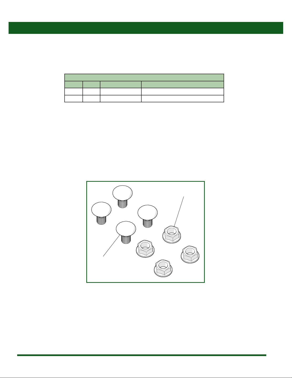
Hardware Bag ................................................................................. 7
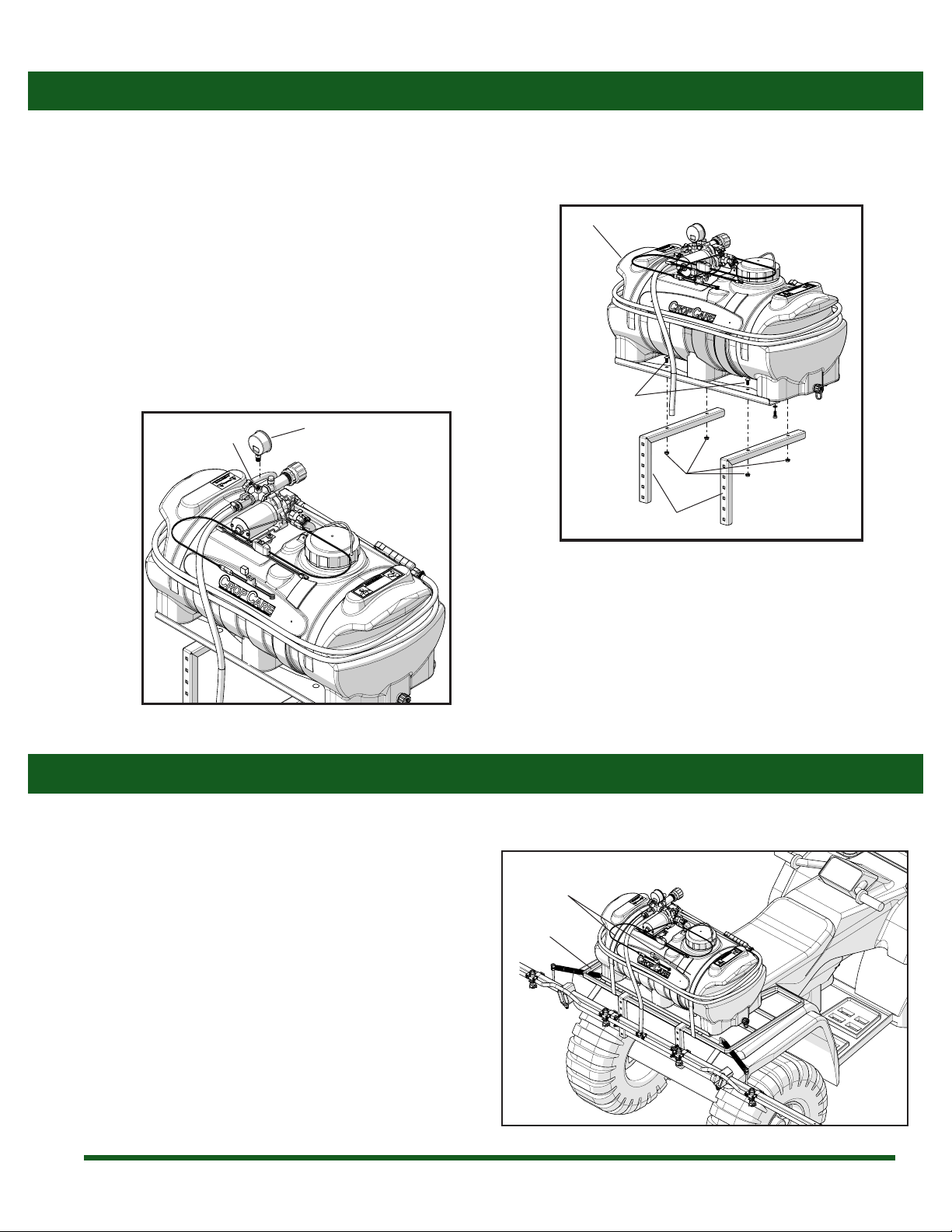
Assembly Instructions ............................................................................ 8
Boom Mount Bracket & Gauge Assembly............................. 8
Mounting the Sprayer............................................................................. 8
Base Unit........................................................................................... 8
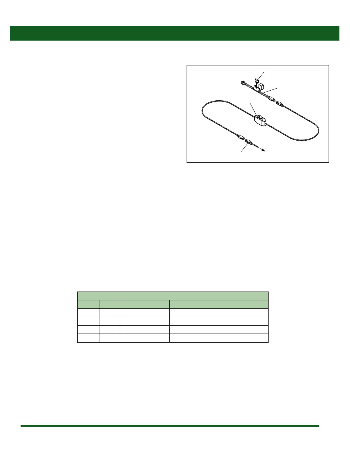
Wiring Harness ............................................................................... 9
Calibrating the Sprayer.........................................................................10
1. Calculating the Speed...........................................................10
2. Determining Nozzle Size/Using Calibrastion Chart....10
3. Adjusting the Sprayer Pressure..........................................11
Boom Calibration Chart.............................................................11
Boomless Nozzle Chart..............................................................11
Operating Instructions .........................................................................12
Spraying with the Boom ...........................................................12
Spraying with the Spray Gun ..................................................12
Following Operation ..................................................................13
Maintenance Instructions ...................................................................13
Routine Maintenance.................................................................13
Winterizing your Sprayer..........................................................14
Troubleshooting .....................................................................................14
Breakdowns and Parts Lists ................................................................15
Base Unit Breakdown.................................................................15
Base Unit Parts List......................................................................16
Shuro® Pump Breakdown & Parts List ...............................17
Relief Valve Breakdown & Parts List ......................................17
CropCare® Limited Warranty ..............................................................18
Ordering Parts .........................................................................................18
Specications
Tank capacity ................................................................................ 25 gal
Min power supply ...................................................12 volt / 10 amp
Wiring harness length ........................................................................ 8’
Pump:
Type...........................................................................Diaphragm pump
Manufacturer ............................................................................ Shuro®
Max pressure..................................................................................45 psi
Max ow rate ............................................................................... 3 gpm
Sprayer:
Spraying width (12’boom)...........................................................160”
Spraying width (20’boomless) ...................................................240”
Hose length (for handgun) .............................................................15’
25 gallon ATV sprayers
Weight:
Base unit (empty) .........................................................................44 lbs
Base unit (full)..............................................................................240 lbs
12’ boom.......................................................................................... 32 lbs
20’ boomless..................................................................................... 5 lbs
Identication of Machine
• Model #’s: ATV-BASE
• The model number and revision identication decal is located on top of the tank .

4
Safety Precautions
Every year many unnecessary accidents occur due to improper equipment handling and a disregard for safety precautions. You, the
operator, can avoid accidents by observing the precautions listed in this section.
Figure 1: Chemical Warning Decal (DEMT3980)
General Guidelines
Figure 2: Owner’s Manual Decal (DE39)
• The operator should be a responsible adult. Do not
allow persons to operate this sprayer until they have
displayed a thorough understanding of sprayer safety
precautions and operational use!
• All operators must also fulll state pesticide applicator
license requirements!
• Never attempt to operate this sprayer when under the
inuence of alcohol or drugs.
• The best defense against accidents is a careful and
responsible operator.
• A chemical warning decal and an owner's manual
warning decal are located on the sprayer’s tank. (Figure
1, Figure 2). Be aware of their location. Always replace
any warning or safety decals that are not legible or are
missing.
• When transporting the sprayer on public roads, always
follow state and local regulations regarding safety and
transportation requirements. Use the necessary lights
and slow moving vehicle (SMV) emblems.
• If there is any portion of this manual that you do not
fully understand, please contact the orignal retailer of
this product.
Read Entire Owner’s
Manual Before Operation
Warning
• Be aware of all safety guidelines, warnings, and cautions including those of the ATV or utility vehicle that the
sprayer may be mounted on.
• Read and understand the chemical manufacturer’s labels, warnings, and instructions.
• Know and fulll all state pesticide applicator license requirements.
• Familiarize yourself and other operators with the sprayer’s components and how all parts are operated.
Before You Begin
Please read and understand this manual and its instructions and warnings completely before operating
the sprayer.

5
Before Operation
• Carefully study and understand this owner's manual.
• Read and follow chemical manufacturer's labels,
warnings, and instructions! A material safety data
sheet (MSDS) should be provided by the chemical
manufacturer.
• To avoid injury from chemical hazards, wear the proper
protective clothing. Each chemical manufacturer's
clothing requirements are listed under the “Personal
Protective Equipment (PPE) section in the chemical
instructions.
• Do not wear loose-tting clothing which may catch in
moving parts.
• Never exceed the ATV or utility vehicle manufacturer's
load rating.
• Give the sprayer a visual inspection for any worn parts,
loose bolts, or other visible problems, and make the
necessary repairs. See the maintenance section for
instructions (page 13).
• Make sure the area is clear of any people or obstructions
before using the sprayer.
• Have all operators practice operating the sprayer and
its attachments, using clean water only, until all persons
are completely capable of safe operation.
During Operation
• Always be aware of bystanders, particularly children!
Always look before moving the sprayer or the ATV.
• No passengers are allowed on or in the ATV or sprayer
at anytime.
• Keep hands and body parts clear of all moving parts.
• Be aware of dangerous terrain such as holes, slopes,
drop-os, banks, rocks, and hidden hazards.
Following Operation
• Operate the ATV and sprayer up and down slopes, not
across.
• Allow for sprayer boom length when making turns.
• Never leave running equipment unattended!
• Rememberthataccidentscanevenhappentoseasoned
operators. Always take your time and follow all safety
instructions.
• Following operation, stop ATV unit, set brakes, shut o
engine, and remove ignition key.
• Store the sprayer away from human and livestock
activity.
• Park the sprayer on a hard level surface
• Do not permit children to play on or around sprayer.
Pump Safety Precautions
• Never pump ammable or explosive uids such as
gasoline, fuel oil, kerosene, etc.
• Note: The pump may be run dry for limited periods of
time without resulting in damage.
• Always disconnect the power to the pump when
working on the pump. Failure to do this could result
in electrical shock.
Safety Precautions

6
ATV-BASE Box
ATV-BASE Kit Contents
ATV-BASE Boxed Contents
Ref # Qty. Part Number Description
1 1 ATV-BASE Sprayer, 25 Gallon ATV Base Kit
2 2 T229 ATV Mounting Bracket
3 1 ATV-BASEOM Manual, Owner’s ATV Srayer Base Kit
4 1 GG60 Gauge, 2-1/2” Liquid Filled 60 PSI
5 1 -- Hardware Bag
3
5
2
1
Figure 1: ATV-BASE Boxed Contents
4

7
Hardware Bag
ATV-BASE Kit Contents
Hardware Bag Contents
Ref # Qty. Part Number Description
6 4 CB38*34G5 Bolt, Carriage 3/8-16 x 3/4" Gr 5
7 4 FN38 Nut, Flange 3/8-16
6
7
Figure 2: Hardware Bag Contents

8
Boom Mount Bracket & Gauge Assembly
Assembly Instructions
Figure 1: Boom Bracket Installation
Figure 2: Pressure Gauge Installation
1. Attach the ATV-BASE (1) to the boom mounting brackets (2)
with four carriage bolts (6) and four ange nuts (7) as seen
in gure 1.
2. Thread the pressure gauge into the top of the 4-way
cross tting (a) as seen in gure 2. Note: Use a wrench
on the gauge’s brass nut to tighten the gauge. Do not thread
the pressure gauge by hand or over-tighten the gauge, as
this could cause damage to the pressure gauge (4)or the
4-way cross component (a).
4
a
2
6
7
1
Mounting the Sprayer
This sprayer is designed to be mounted on the rack or on the back of most ATVs and utility vehicles. Mounting the sprayer correctly
and securely will ensure accurate, consistent and safe spraying.
1. Before installing your sprayer, make sure that the sprayer
unit does not exceed the ATV manufacturer's load rating.
The sprayer unit could weigh up to 270 lbs when lled
with 25 gallons of liquid.
2. In most cases, the sprayer unit is placed on the rear rack
of the ATV and is securely strapped down. In a more
permanent situation the sprayer unit could also be
bolted down. Regardless of how the sprayer is mounted,
it is essential that sprayer is properly secured (Figure 3).
Figure 3: Mounting the sprayer
Base Unit Strap
ATV Rear Rack

9
Wiring Harness
Figure 1: Wiring Harness
1
2
3
4
To Pump Motor
Mounting the Sprayer
Wiring Harness
Ref # Qty. Part Number Description
1 1 -- Motor Plug End
2 1 SPT-SWH-9615A-16G Harness, Wiring 8 Ft w/ Switch
3 1 SPT-BCG-1215A-16G Harness, Battery Connector w/15A Fuse
4 1 ATC-15 Fuse, 15 Amp Buss
1. The wiring harness needs to be connected to a DC
power source (vehicle battery) or a power access
point providing atleast 12 volts & 10 amps of current
to the ring terminals on the fuse harness (3) (Figure
1). Note: Make sure that the selected power source
provides the adequate power requirements as stated
above. Inadequate power can cause problems and
performance issues with the pump.
2. Connect the red wire to the positive terminal on the
vehicle’s battery or other alternate power source
positive terminal. Proceed to connect the black wire
to the negavtive terminal of the vehicle’s battery or a
good ground source. Note: The fused wire harness (3)
(Figure 1) can be unplugged from the switch harness
(2) (Figure 8) and be left attached to the battery or
power source for convenience purposes.
3. Mount the switch (2) (Figure 1) in a location that is
easily accessible for operation on the vehichle. Make
sure to secure the switch so that it cannot fall out of
place or become entangled and cause damage. Note:
Use caution when routing the wiring harness to avoid
areas where the wires could become pinched, rubbed,
or exposed to excessive heat.

10
Note: All calibration needs to be done with water only!
When spraying with the boom, the sprayer must be calibrated to ensure proper spray coverage. Before calibrating the sprayer, it is
important to familiarize yourself with the operating instructions (page 10). The calibration process is simplied when broken down
into the following three steps:
1. Calculate the speed of the ATV or utility vehicle.
2. Determine the nozzle size and consult the calibration chart for the desired or instructed Gallons per Acre (GPA).
3. Set the the pressure accordingly using the relief valve.
1. Calculating the Speed
It is important to determine what speed your ATV will be traveling at while spraying. While some ATVs may have speedometers, it
is still recommended that speed be calculated for all ATVs for accuracy purposes. To determine the speed follow these four steps:
Note: It is helpful for future references to record the
exact RPM and gear used to nd your speed.
Speed in MPH
Time required (seconds) to travel
a distance of:
200 feet 300 feet
1.0 136 205
1.5 91 136
2.0 68 102
2.5 55 82
3.0 45 68
3.5 39 58
4.0 34 51
4.5 30 45
5.0 27 41
5.5 25 37
6.0 23 34
6.5 21 31
7.0 19 29
Calibrating the Sprayer
2. Determining Nozzle Size/Using Calibration Chart
The spray nozzles on your sprayer are color-coded to match up with the calibration chart. After you have determined your nozzle
size, you need to look at the calibration chart. Using your ATV speed, nozzle size, and desired gallons per acre (GPA), nd the
pressure (psi) necessary to achieve your GPA. It is important to note that lower pressure settings will result in less spray drift.
Example: Assume you have found your ATV speed to be 5 MPH, your nozzles are yellow (XR11002), and you want to spray 10 GPA.
Upon looking at the chart, you nd that you should set the sprayer's pressure at about 30 psi in order to apply 10 GPA.
1. Measure a 200 foot or 300 foot distance on a eld or a
surface similar to where you will be spraying.
2. Drive the equipment and sprayer (half-full is optimal)
across the measured distance at a constant rate of
speed. There can be no changes in speed while you are
measuring the time. This should be a comfortable speed
for spraying.
3. Have someone measure the amount of time (in seconds)
it takes to travel the measured distance.
4. Your speed can be calculated by entering your data into
the equation Speed (mph) = (Distance (ft) x 60) / (Time
(seconds) x 88) or by consulting the table to the left.

11
Tip Size PSI GPM of one
nozzle
Gallons Per Acre (GPA)
3 MPH 4 MPH 5 MPH 6 MPH
XR110015
(Green)
15 0.092 9.2 6.8 5.5 4.6
20 0.11 10.8 8.2 6.5 5.4
30 0.13 12.8 9.7 7.7 6.4
40 0.15 14.8 11.1 8.9 7.4
XR11002
(Standard size)
(Yellow)
15 0.12 11.8 8.9 7.1 5.9
20 0.14 13.8 10.4 8.3 6.9
30 0.17 16.8 12.6 10.1 8.4
40 0.20 19.8 14.9 11.9 9.9
XR110025
(Lavender)
15 0.15 14.8 11.1 8.9 7.4
20 0.18 17.8 13.4 10.7 8.9
30 0.22 21.8 16.3 13.1 10.9
40 0.25 24.8 18.6 14.9 12.4
Please note: Flow rates are calculated using water.
Boom Calibration Chart
Boomless Nozzle Calibration Chart
Tip Size PSI GPM
of two nozzles
Spray Width in
Feet
Gallons Per Acre
24” Height
Gallons Per Acre
36” Height
24”
Height
36”
Height
3
MPH
4
MPH
6
MPH
8
MPH
3
MPH
4
MPH
6
MPH
8
MPH
1/4XP10
(Orange)
20 1.42 17 20 13.8 10.3 6.9 5.2 11.8 8.8 5.9 4.4
30 1.74 20 22 14.4 10.8 7.2 5.4 13.0 9.8 6.5 4.9
40 2.00 22 25 15.0 11.3 7.5 5.6 13.2 9.9 6.6 5.0
Please note: Flow rates are calculated using water.
Calibrating the Sprayer
3. Adjusting the Sprayer Pressure
You have found the correct pressure setting, but must now
adjust the sprayer to that pressure setting. The relief valve
(2) (Figure 1) controls the sprayer's pressure and is located
in front of the pressure gauge (1) (Figure 1). Before spraying,
turn the relief valve and watch the pressure gauge until it
reads the correct pressure found from step 2 on page 10. You
now have successfully calibrated the sprayer.
Figure 1: Adjusting the Sprayer Pressure
12
3

12
Spraying with the Boom
Operating Instructions
1. Calibrate the sprayer using the preceding calibration
instructions and chart (page 10). This will determine
what pressure to spray at in order to achieve the desired
gallons per acre (GPA).
2. Fill the tank with some water in order to set the pressure
and test for leaks.
3. Prepare the sprayer for spraying by closing the ball valve
(3) in the boom supply line (Figure 1, pg 11).
4. Start the ATV and engage the pump by turning on the
power switch (2) (Figure 1, pg 9) on the wiring harness.
Check the sprayer to be sure that there are no leaks in
any of the hoses.
5. Using the relief valve (2) (Figure 1, pg 11), adjust the
sprayer's pressure to the calculated pressure rating
found when you calibrated your sprayer. When you
open the boom supply line valve you may need to re-
adjust the pressure.
Note: Since the maximum pump pressure is 45 psi, setting the pressure above 45 psi will cause the pump to pulsate on and o.
Spraying with the Spray Gun
1. Fill the tank with some water in order to set the pressure
and test for leaks.
2. Prepare the sprayer for spraying by closing the ball valve
(3) (Figure 1, pg 11) in the boom supply line
3. Start the ATV and engage the pump by turning on the
power switch (2) (Figure 1, pg 9) on the wiring harness.
Check the sprayer to be sure that there are no leaks in
any of the lines.
4. Adjust the sprayer's pressure using the relief valve (2)
(Figure 1, pg 11) to your desired setting
5. Turn o the pump using the power switch (2) (Figure 1,
pg 9) on the wiring harness.
Before operating the sprayer, it is important that you read this entire manual and know all safety precautions. Always take your time
and be alert when operating your sprayer in order to avoid an accident.
6. Turn o the pump using the power switch (2) (Figure 1, pg
9) on the wiring harness.
7. You may now ll the tank with the correct amount of water
and chemicals that is recommended by the chemical
being used.
8. After the tank is full, close the boom supply valve (3)
(Figure 1, pg 11), engage the pump by turning on the
power switch (2) (Figure 1, pg 9) and allow the water to
circulate to ensure proper mixing of the chemicals and
water. You are now ready to begin spraying.
9. Upon arriving at the spraying location, unfold the boom
wings, engage the pump by turning on the power switch
(2) (Figure 1, pg 9), open the boom supply valve (3) (Figure
1, pg 11), and make sure the pressure setting is correct.
6. You may now ll the tank with the correct amount of
water and chemicals recommended by the chemical
being used.
7. After the tank is full, engage the pump by turning on the
power switch (2) (Figure 1, pg 9) and allow the water to
circulate to ensure proper mixing of the chemicals and
water. You are now ready to begin spraying.
8. Upon arriving at the spraying location, engage the
pump, and make sure the pressure setting is correct.
Press the trigger on the spray gun to engage the gun.
Note: The tip at the end of the gun can be turned to
adjust the spray pattern.

13
Operating Instructions
Routine Maintenance
It is very important to perform routine maintenance on your sprayer before and after each use. Good maintenance practices will help
to guard against any unnecessary sprayer breakdowns or accidents.
1. It is recommended to perform a visual and physical inspection
foranywornparts,loosebolts,orothervisibleproblems.Makeall
necessary repairs before spraying. Contact the original retailer
for instructions on ordering parts and technical help.
2. After each use it is important to rinse the pump and all
components by running water through the system. Fill the
tank with a sucient amount of fresh water and engage both
the spray gun and the boom. Rinsing the pump with fresh
water will greatly improve the life of the pump.
Note: Due to normal wear, Teejet®recommends that you replace your sprayer nozzles after every spraying season. Nozzle
replacement will ensure accurate spraying performance.
3. Always follow all pump safety precautions and warnings
(See page 5). Following these guidelines will help
increase the longevity of the pump.
4. The suction strainer located on the end of suction hose
(REF # 14, pg 15) should be inspected and rinsed o on
a regular basis.
Following Operation
1. Thoroughly rinse the sprayer of any chemical residue is
important. It is recommended to ll the tank with fresh
water and engage the spray gun and boom until the
system is entirely free of chemical residue.
2. Do not not to rinse the sprayer in an area if other humans,
animals, or sensitive plants are present and could come in
contact with chemical residue.
3. Store the sprayer in a location where it will be away from
human or animal activity. Do not allow children to play
on or near the sprayer.
Maintenance Instructions

14
It is essential that you winterize your sprayer to avoid damage and allow for optimal performance. The winterization process should
be performed before freezing conditions or after each season of use. Failure to winterize your sprayer will void the manufacturer’s
warranty and could cause damage to the sprayer.
Winterizing your Sprayer
1. Verify that the tank is empty and rinsed out. Pour 1/2
to 1 gallon of RV non-toxic antifreeze into the tank.
Note: It is not recommended to use standard antifreeze.
Standard antifreeze can be harmful to humans, animals,
crops, and the environment.
2. Engage the pump by turning on the power switch (2)
(Figure 1, pg 9), then spray with the boom and the spray
gun. Note: Be sure that the antifreeze has been pumped
through the entire system including all spray nozzles.
Troubleshooting
As you use your ATV sprayer, it is possible that you will encounter minor problems that can be easily xed. The following problems
and respective causes and solutions should cover most of the potential problems that you may face. If you are having problems
please attempt to use this troubleshooting section to solve the problem. If you are unable to x the problem please contact the
orignal retailer of this product for service.
Problems/Symptoms Possible Causes Solutions
Low Rate of Flow
Suction Strainer is partially clogged Remove the suction strainer and rinse
Tip strainer is clogged Remove tip strainer and rinse
Pump valves are damaged/bad Replace the valves or contact the original retailer for repairs
Low voltage Use a power source with at least 10 amps and 12 volts
Pump Will Not Prime
Suction line is clogged Inspect the suction line for debris
Suction strainer is clogged Remove the suction strainer and rinse
Pump is damaged from chemicals not being
properly rinsed out Contact the original retailer for service and repairs
Pump Will Not Run
Fuse is blown Replace the fuse on the wiring harness
Incorrect voltage Ensure that a 10 amp, 12 volt power source is being used
Pump pressure switch is malfunctioning Contact the original retailer for service and repairs
No Spray Flow
Spray tip is clogged Remove the spray tip and rinse out
Suction strainer is clogged Remove the suction strainer and rinse
Nozzle tip strainer is clogged Remove the nozzle tip strainer and rinse
Pump Pulsates On and O Pressure is set above pump limit (45 psi) Lower the pressure with the relief valve
Defective pump demand switch Contact the original retailer for service and repairs
3. Store the sprayer in a dry location away from the elements.
4. Before spraying in the spring it is recommended to ush
the sprayer with fresh water to cleanse it of the antifreeze
and any other buildup. Note: Perform a thorough
inspection of all sprayer components before spraying.
Maintenance Instructions

15
Breakdowns & Parts Lists
Base Unit Breakdown
To Boom
3
4
5
9
10
11
12
13
14
15
16
2
6
7
8
1
23
24
25
29
30
31
32
33
34
35
36
22
26
27
28
21
17
18
19
20
37
38
39
40
41
2
2
10
13
13
13
18
24
28
42

16
Base Unit Parts List
* Included with spray gun part number (5080015PP406)
** Included with tank part number (T247)
*** Under heat shrink tubing on pump
**** Additional Breakdowns Available
Breakdowns & Parts Lists
Ref# Qty. Part Number Description
1 14' 1206 Hose, EPDM Rubber 3/8" 200 PSI
2 5.5' 1208 Hose, EPDM Rubber 1/2" 200 PSI
3 1 10035** Lid, Tank 5" w/ out Lanyard
4 1 10873** Lanyard, 12"
5 1 10960** Gasket, Tank Outlet Cap for Den Hartog Applicator Tank
6 1 11042 Gasket, EPDM for 5" Lid
7 1 19024** Cap, Tank Outlet for Den Hartog Applicator Tank
8 1 19025** Tether, Cap Tank Outlet for Den Hartog Applicator Tank
9 1 47965 Extension, Wiring Harness 12" 14 GA
10 2 62606 Hose Clamp, Narrow 5/16"-7/8" SS
11 2 506346*** Connector, Wire Butt Terminal 16-14 Ga Insulated
12 1 803401 Adapter, Hose 90° 1/2" FPT x 1/2" HB
13 4 6806052 Hose Clamp, 1/2" - 29/32" SS
14 1 10416D Strainer, Suction 3/8" FPT 40 Mesh
15 1 2088-343-135 Pump, ShurFlo 12V 3 GPM Vi-Santo
16 1 2312012PP Valve, Relief 1/2" NPT Poly 150 PSI piston-type
17 1 38720PPBX18* Adjustable spray nozzle, #18
18 2 3A1212 Adapter, Hose 1/2" MPT x 1/2" HB
19 1 3A3812 Fitting, Hose 3/8" MPT x 1/2" HB
20 1 3EL1238 Elbow, Hose 90° 1/2" MPT x 3/8" HB
21 1 5080015PP406 Spray Gun, TriggerJet 15" Poly Ext 3/8" HB Inlet X18 Tip
22 1 90FMB12 Valve, Ball 1/2" FPT x 1/2" MPT 300PSI
23 1 C13201 Clip, Medium Grip
24 4 CB38*34G5 Bolt, Carriage 3/8-16 x 3/4" Gr 5
25 1 DE39 Decal, "Warning Read Owner's Manual" 2" x 3"
26 1 DE46 Decal, CropCare Logo 1.9" x 8.8"
27 1 DEMT3980 Decal, "Warning Avoid Injury Follow Labels"
28 4 FN38 Nut, Flange 3/8-16
29 1 GCR1214 Cross, Gauge Port 1/2" FPT 1/4" FPT Poly
30 1 GG60 Gauge, 2-1/2" Liquid Filled 60 PSI
31 6 H5C516*34 Bolt, Hex 5/16-18 x 3/4" Gr 5
32 1 HST38*3 Heat shrink tubing, 3/8" x 3" long
33 6 LW516 Washer, Lock 5/16"
34 2 MR1024*38S Screw, Machine Rd Hd 10-24 x 3/8" SS
35 1 N189472 Clip, Gripper 3/8" - 5/8" Zinc
36 1 T247**** ATV Base Kit, Tank
37 4 SBT316*1 Bolt, Stove Truss Head 10-24 x 1"
38 1 SPT-BCG-1215A-16G Harness, Battery Connector w/15A Fuse
39 1 SPT-SWH-9615A-16G Harness, Wiring 8 Ft w/ Switch
40 2 T229 ATV Mounting Bracket
41 2 T231 ATV Tank Mount
42 1 DE170 Decal, Model ATV-BASE, Rev. B.1

17
Shuro®Pump Breakdown & Parts List
Ref # Qty. Part Number Description
1 1 94-236-11 Complete pump head
2 1 94-230-36 Switch kit, 45 psi
3 1 94-231-30 Upper housing kit (does not include switch)
4 1 94-232-05 Viton valve kit
5 1 94-238-03 Drive kit with diaphragm
2
5
4
1
3
Breakdowns & Parts Lists
Model: 2088-343-135
Relief Valve Breakdown & Parts List
Ref # Qty. Part Number Description
1 1 CP23122-NY Nylon adjusting cap
2 1 -- Polypropylene spring retainer
3 1 -- Stainless retaining pin
4 1 -- EPDM rubber O-ring
5 1 -- Stainless spring
6 1 -- Polypropylene guide seat
7 1 CP23123-PP Poly lock ring
8 1 CP23128-PP Polypropylene body, 1/2” MNPT
2
6
7
8
5
4
1
3
* Spare parts kit PK-AB23120-KIT includes ref. #’s 3, 4, 5

18
CropCare®Limited Warranty
CropCare®hereby provides a Limited One (1) Year Warranty on ATV Sprayers, manufactured by CropCare®. ATV Sprayers
manufactured by CropCare®are warrantied against any manufacturer’s defects in any of the sprayer’s components in the 12 months
following the original date of purchase.
Defective components will be repaired or replaced at the discretion of the manufacturer. It is the responsibility of the purchaser to
return warranted components to the manufacturer. This warranty is limited to the repair or replacement of sprayer components
only. CropCare®is not to be held liable for incidental or consequential damages of any kind. This warranty covers the purchaser of
this sprayer and any other owners who own it during the one year warranty period.
To retain the warranty, the sprayer must be operated and maintained as ascribed by its owner’s manual. For warranty service, please
have a copy of the purchase invoice available.
All ATV Sprayer warranty claims must be made through the original retailer. All warranty claims must be submitted with an
invoice or a proof of purchase that denotes the purchase date and place of purchase.
Warranty Coverage
Warranty Is Void if:
Getting Warranty Service
1. The sprayer has been subjected to, in the opinion of CropCare®, negligent handling, misuse, an accident or if the instructions in
the owner's manual were not completely followed.
2. The sprayer's components have been altered in any manner or repairs have taken place with unapproved parts.
3. The sprayer and its components were subject to freezing or freezing conditions. The sprayer must have been winterized as per
the maintenance instructions to retain the warranty.
4. A non-compatible chemical was used and/or if the sprayer operator failed to rinse all chemical residue out of the sprayer's
components after use.
5. A petroleum-based, oil-based, or ammable product was used and caused damage to the pump, tank, hoses, or any other
component.
ATV Sprayer: Model ATV-BASE
Ordering Parts
Please contact the original retailer to order replacement parts for your product.

19
Manufactured by PBZ LLC
A Paul B Zimmerman Inc. Company
www.CropCareEquipment.com
Table of contents
Other PBZ Paint Sprayer manuals
Popular Paint Sprayer manuals by other brands

ESS
ESS BP1 owner's manual

Gröne
Gröne EasySpray 19 Operating instruction

DS Produkte
DS Produkte Q0P-WYT16-18 Translation of the original operating instructions

Anest Iwata
Anest Iwata Classic plus Series instruction manual

Volpi
Volpi v.black KOMFORT 12 Instructions for use

One Stop Gardens
One Stop Gardens CADDY SPRAYER 96622 operating instructions