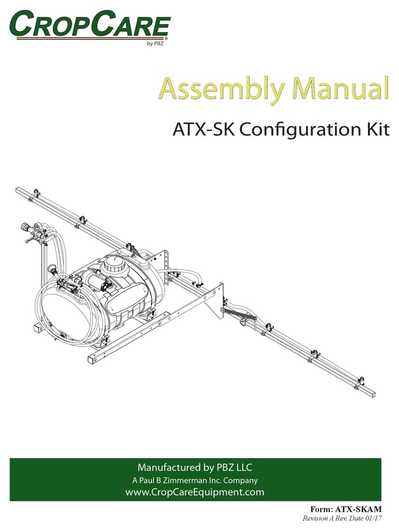
PBZ CropCare ATX60-TR-G User manual

by PBZ
60 Gallon Trailer Sprayer, with Gas
Engine and Diaphragm Pump
Model: ATX60-TR-G
Form: ATX60-TR-GAM
Rev A Date 1/21
Assembly Manual
Manufactured by PBZ LLC
A Paul B Zimmerman Inc. Company
www.CropCareEquipment.com

2
The ATX60-TR-G comes partially assembled and requires some assembly. Use the assembly instructions to ensure proper assembly.
Before assembling, ensure that the boxes contain the necessary components and parts.
Assembly Instructions
Installation Time:
• Approximately 3-4 hours
Recommended Tools
• 7/16” socket or wrench
• 1/2” socket or wrench
• 9/16” socket or wrench
• 3/4” socket or wrench
• 5/32” Allen Wrench
• Adjustable wrench or pliers
• Hose cutter or knife to cut hoses to length
• Battery or air powered impact
• Pipe Tape and Thread Sealant

3
Box Contents (Tank, Base Frame, and Controls)
Assembly Instructions
Item Qty. Part Number Description
1 1 ------------------- Assembled Tank and Base
2 1 ------------------- Assembled Controls
3 1 ------------------- Assembled Spray Gun
4 1 ------------------- Assembled Valve and Filter
5 1 ------------------- Assembled Tee
6 22 FT 1008 Hose, EPDM Rubber 1/2"
7 3.5 FT 1008 Hose, EPDM Rubber 1/2"
8 6.25 FT 1010 Hose, EPDM Rubber 5/8"
9 1.5 FT 3003 Hose, Suction 3/4" Clear PVC 100 PSI
10 1 ATX60-TR-GOM Owner's Manual, ATX60-TR-G
11 1 T702 Boom mounting angle, right
12 1 T703 Boom mounting angle, left
13 1 T714 Control mounting post
3
4
5
9
10
11
12
13
2
6
78
1

4
Assembly Instructions
Hardware Bag (Tank, Base Frame, and Controls)
Item Qty. Part Number Description
1 1 17000091 * Gasket, Strainer 3350 1/2" & 3/4" EPDM
2 4 CB38*3G5 Bolt, Carriage 3/8-16 x 3" Gr 5
3 1 CB38*2G5 Bolt, Carriage 3/8-16 x 1-3/4" Gr 5
4 2 CB38*4G5 Bolt, Carriage 3/8-16 x 4" Gr 5
5 1 EW12 Washer, Lock External-Tooth 1/2"
6 7 FN38 Nut, Flange 3/8-16
7 9 6806052 Hose Clamp, 1/2" - 29/32" SS
8 4 6810052 Hose Clamp, 1/2" - 1-1/16" SS
9 1 2841240 Plug, 3/8”G plastic
10 1 FW12 Washer, Flat 1/2” USS
* NOTE: Item 1 is a spare gasket for the suction line lter.
3
45
8
2
6
7
1
9
10

5
Box Contents (Axle, Wheels, Hitch, Motor, and Pump)
Assembly Instructions
Item Qty. Part Number Description
1 1 ------------------- Assembled Motor and Pump
2 2 MW18958HS1R4 Tire, 18 x 950-8, 1" Bore x 3-1/4"
3 1 T718 Hitch tube
4 2 T731 Trailer axle bracket
5 2 T745 Trailer Arm
3
4
5
2
1

6
Assembly Instructions
Hardware Bag (Axle, Wheels, Hitch, Motor, and Pump)
Item Qty. Part Number Description
1 2 1000P Shaft Collar, 1"
2 1 18812 Pin, Hitch T-Handle 1/2" x 2-1/4"
3 2 T716 Bushing, Bolt
4 6 FN12 Nut, Flange 1/2-13
5 8 FN38 Nut, Flange 3/8-16
6 2 FW12 Washer, Flat 1/2" USS
7 2 CB12*3G5 Bolt, Carriage 1/2-13 x 3" Gr 5
8 2 CB38*3G5 Bolt, Carriage 3/8-16 x 3" Gr 5
9 2 CB38*314G5 Bolt, Carriage 3/8-16 x 3-1/4" Gr 5
10 4 CB38*312G5 Bolt, Carriage 3/8-16 x 3-1/2" Gr 5
11 4 CB12*1G5 Bolt, Carriage 1/2-13 x 1" Gr 5
12 1 CP11516 Clip Pin .125" x 1-15/16" 7/16"E
13 1 9910110130 Adapter, 1/2" HB x 1/2" BSP Wing Nut Assy
3
4
5
9
10
2
6
7
8
1
11
12
13

7
Assembly Instructions
Step 1 (x2)
• Install the axles onto the base frame.
Item Qty. Part Number Description
1 1 ------------------- Assembled Tank and Base
2 2 T731 Trailer axle bracket
3 4 CB38*312G5 Bolt, Carriage 3/8-16 x 3-1/2" Gr 5
4 4 FN38 Nut, Flange 3/8-16
3
4
2
1

8
Assembly Instructions
Step 2 (x2)
• Install the wheels onto the axles.
Item Qty. Part Number Description
1 2 1000P Shaft Collar, 1"
2 2 MW18958HS1R4 Tire, 18 x 950-8 Scorpion 1" Bore x 3-1/4"
3
21

9
Assembly Instructions
Step 3
Item Qty. Part Number Description
1 1 T718 Hitch tube
2 2 T745 Trailer Arm
3 2 T716 Bushing, Bolt
4 2 CB38*314G5 Bolt, Carriage 3/8-16 x 3-1/4" Gr 5
5 2 CB38*3G5 Bolt, Carriage 3/8-16 x 3" Gr 5
6 2 FN12 Nut, Flange 1/2-13
7 4 FN38 Nut, Flange 3/8-16
8 2 FW12 Washer, Flat 1/2" USS
9 2 CB12*3G5 Bolt, Carriage 1/2-13 x 3" Gr 5
10 1 18812 Pin, Hitch T-Handle 1/2" x 2-1/4"
11 1 CP11516 Clip Pin .125" x 1-15/16" 7/16"E
• Install the hitch onto the front of the trailer.
• NOTE: There are several mounting options to set the hitch height to match the draw bar height of the tow vehicle. Set the hitch
height so that the tank is as close to level as possible.
• The hitch arms (Item 2) can be adjusted by which hole is used in the base frame (a).
• The hitch (Item 1) can be rotated to have the bent tab (b) on the top or the bottom.
3
4
5
9
10
2
6
7
8
1
b
a
2
3
6
7
7
8
9
11

10
Assembly Instructions
Step 4
Item Qty. Part Number Description
1 1 ------------------- Assembled Valve and Filter
• Install the lter and valve assembly into the bulkhead tting on the bottom of the tank. Use thread tape and sealant on threads.
• NOTE: Rotate the assembly slightly to the left side of the unit (facing from the hitch end of the trailer). This will allow the hose
connecting the pump inlet to t better.
1

11
Assembly Instructions
Step 5
Item Qty. Part Number Description
1 1 ------------------- Assembled Motor and Pump
2 4 FN12 Nut, Flange 1/2-13
3 4 CB12*1G5 Bolt, Carriage 1/2-13 x 1" Gr 5
4 1 9910110130 Adapter, 1/2" HB x 1/2" BSP Wing Nut Assy
• Install the motor and pump assembly.
• Install hose adapter (Item 4) onto pump.
3
2
1
2
2
3
4

12
Assembly Instructions
Step 6
Item Qty. Part Number Description
1 1 ------------------- Assembled Controls
2 1 T714 Control mounting post
3 2 CB38*4G5 Bolt, Carriage 3/8-16 x 4" Gr 5
4 1 CB38*134G5 Bolt, Carriage 3/8-16 x 1-3/4" Gr 5
5 1 EW38 Washer, Lock External-Tooth 3/8"
6 3 FN38 Nut, Flange 3/8-16
7 1 FW12 Washer, Flat 1/2” USS
• Install the control mounting post and controls.
• NOTE: Item 2 can be positioned slightly forward or straight to position the controls. Item 1 can be moved forward or back for farther
adjustment, based on which hole is bolted through to the post. (Shown with controls positioned forward.)
3
4
5
2
6
1
6
7

13
Assembly Instructions
Step 7
Item Qty. Part Number Description
1 1 T702 Boom Mounting Angle, Side A
2 1 T703 Boom Mounting Angle, Side B
3 4 CB38*3G5 Bolt, Carriage 3/8-16 x 3" Gr 5
4 4 FN38 Nut, Flange 3/8-16
• Install boom mounting brackets. Brackets can be bolted on in several dierent ways, or switched from side to side as needed to t
the boom.
3
4
2
1
3
4

14
Assembly Instructions
Step 8
Item Qty. Part Number Description
1 1.5 FT 3003 Hose, Suction 3/4" Clear PVC 100 PSI
2 2 6810052 Hose Clamp, 1/2" - 1-1/16" SS
• Connect the suction hose to the hose barb tting (a) on the lter to the hose barb (b) on the pump.
2 1
2 b
a

15
Assembly Instructions
Step 9
• Install the hose from the hose barb (a) on the pump to the hose barb (b) on the control assembly.
• Cut the hose in between the pump and controls, and install the assembled tee ttings (Item 1) to be used to connect to the spray
gun.
Item Qty. Part Number Description
1 1 ------------------- Assembled Tee
2 3.5 FT 1008 Hose, EPDM Rubber 1/2"
3 4 6806052 Hose Clamp, 1/2" - 29/32" SS
a
b
3
1
2
2
3
3
3

16
Assembly Instructions
Step 10
• Install the spray gun assembly onto the tee tting (a).
Item Qty. Part Number Description
1 1 ------------------- Assembled Spray Gun
2 1 6806052 Hose Clamp, 1/2" - 29/32" SS
a
2
1
1

17
Item Qty. Part Number Description
1 6.25FT 1010 Hose, EPDM Rubber 5/8”
2 2 6810052 Hose Clamp, 1/2" - 1-1/16" SS
Assembly Instructions
Step 11
• Install the bypass hose (Item 1). Connect the hose to the hose barb on the controls (a), and rout hose underneath the tank to the
bypass inlet elbow (b).
a
b
1
1
2
2

18
Item Qty. Part Number Description
1 1 2841240 Plug
Assembly Instructions
Step 12
• If the boom only has one section, remove the one valve (a) from the controls, and replace with threaded plug.
• NOTE: There is an o-ring at the valve tting, make sure to re-use this o-ring for the plug.
1
a

19
Item Qty. Part Number Description
1 22 FT 1008 Hose, EPDM Rubber 1/2"
2 4 6806052 Hose Clamp, 1/2" - 29/32" SS
Assembly Instructions
Step 13
• Install the boom supply hoses onto valves, and route the hoses back under the frame. Connect to boom.
IMPORTANT: Before use, be sure to do the following:
• Read the owner’s manual. Follow all safety and use instructions.
• Check the oil level on the pump (see pump owners manual for details). Add oil as needed.
• Check the air pressure of the pump diaphragm (see pump owners manual for details).
• Check the oil and fuel levels of the gas engine (see engine owner’s manual for details).
2
1
2

Manufactured by PBZ LLC
A Paul B Zimmerman Inc. Company
Congratulations, your new CropCare® sprayer is assembled
and ready for years of use!
Contact us with questions or concerns at:
Info.cropcar[email protected]om
Or nd additional support materials at:
CropCareEquipment.com
Table of contents
Other PBZ Paint Sprayer manuals
Popular Paint Sprayer manuals by other brands

q-Tech
q-Tech QT650 user manual

Central Pneumatic
Central Pneumatic HVLP DETAIL SPRAY GUN 46719 owner's manual

Hudson
Hudson Bleach Solutions 90011 instructions

Spraying Systems
Spraying Systems TeeJet TECHNOLOGIES BoomPilot installation manual

Gema
Gema OptiFeed B Operating instructions and spare parts list

Central Pneumatic
Central Pneumatic CENTRAL PNEUMATIC 93305 Startup guide