PBZ CropCare ATV-MX240 User manual

by PBZ
20’ Manual Fold Boom
Model ATV-MX240
Form: ATV-MX240OM
Revision A Rev. Date 01/17
Manufactured by PBZ LLC
A Paul B Zimmerman Inc. Company
www.CropCareEquipment.com
Owner's Manual

2
Notes

3
Table Of Contents
• Be aware of all safety guidelines, warnings, and cautions including those of the tractor manufacturer.
• Read and understand the chemical manufacturer’s labels, warnings, and instructions.
• Know and fulll all state pesticide applicator license requirements.
• Familiarize yourself and other operators with the sprayer’s components and how all parts are operated.
Before You Begin
Please read and understand this manual and its instructions and warnings completely before operating.
Before You Begin....................................................................................3
Safety Precautions.................................................................................4
Before Operation ........................................................................4
During Operation .......................................................................4
Following Operation .................................................................4
Transporting the Sprayer.........................................................4
Assembly Instructions .....................................................................5-7
ATV-MX240 Kit Contents..........................................................5
ATV-MX240 Assembly Instructions.................................. 6,7
F2500 Assembly Instructions .................................................8
Operating Instructions ........................................................................9
Boom Operation .........................................................................9
Calibrating the Sprayer.....................................................................10
Calculating the Speed............................................................ 10
Determining Nozzle Size/Using Calibration Chart ...... 10
Maintenance Instructions ............................................................... 11
Winterizing your Sprayer ...................................................... 11
Routine Maintenance............................................................. 11
Breakdowns & Parts List.............................................................11-13
TeeJet® Nozzle Body Breakdown & Parts List ................ 11
ATV-MX240 Breakdown......................................................... 12
ATV-MX240 Parts List .............................................................13
CropCare® Limited Warranty .......................................................... 14
Ordering Parts ..................................................................................... 14

4
During Operation
• To avoid injury from chemical hazards, wear the proper
protective clothing. Each chemical manufacturer’s
clothing requirements are listed under the “Personal
Protective Equipment (PPE) section in the chemical’s
instructions
• Always be aware of bystanders, particularly children!
Always look before moving the sprayer or engaging the
pump. Bystanders should never be allowed near the
sprayer during operation.
Transporting the Sprayer
• When transporting the sprayer, the sprayer’s boom
must be in the fully folded position.
Safety Precautions
• Completely rinse the entire boom and all of its
components of all chemical residue after every use.
Following Operation
• Dispose of rinsate in accordance with chemical
application guidelines.
• Be aware of dangerous terrain such as holes, slopes,
drop-os, banks, rocks, and hidden hazards. Operate
the tractor and sprayer up and down slopes, not across.
• Allow for sprayer boom length when making turns.
• Rememberthataccidentscanevenhappentoseasoned
operators. Always take your time and follow all safety
instructions.
Before Operation
• Be aware of the location of all the safety and warning
decals. Always replace any decals that are illegible or are
missing.
• Carefully study and understand this owner’s manual.
• Give the boom a visual inspection for any worn parts,
loose bolts, or other visible problems, and make any
necessary repairs. See the maintenance section(page 9).
• All maintenance should be performed with the sprayer
unhooked from the tractor and clean of any harmful
chemicals.
• Make sure the area is clear of any people or obstructions
before using the sprayer.

5
Assembly Instructions
Figure 1: Boom hardware and nozzle kit
ATV-MX240 Boxed Contents
Ref # Qty. Part Number Description
1 1 -- Center Frame
2 1 -- Left Wing
3 1 -- Right Wing
4 1 HDKMX240 Hardware & Nozzle Kit
5 1 ATV-MX240OM Manual, Owner’s ATV Manual Fold Boom 20’
HDKMX240 Hardware & Nozzle Kit Contents (Figure 1)
Ref # Qty. Part Number Description
6 3 6806052 Hose Clamp, 1/2" - 29/32" SS
7 2 AN38 Nut, Acorn 3/8-16
8 2 C-267 Spring, Hard Drawn Zinc, 26 lbs/in
9 2 CB38*1G5 Bolt, Carriage 3/8-16 x 1" Gr 5
10 6 CB38*214G5 Bolt, Carriage 3/8-16 x 2-1/4" Gr 5
11 8 FN38 Nut, Flange 3/8-16
12 2 FW38 Washer, Flat 3/8"
13 2 MX2023 20’ Manual Fold Boom, Mount Bracket
14 12 256121NYR Kit, Cap & Gasket Quick TeeJet Black
15 12 8079PP50 Strainer, Tip 50 Mesh Red Poly Body SS Screen
16 12 AIXR110025VP Tip, AIXR TeeJet Polymer Purple
17 2 AA111SQ112+ Clamp, Square Assembly Boom 1-1/2" Tube
18 4 875UV Cable Tie, 8”75 Lb UV Black
ATV-MX240 Kit Contents
+Only used if installing an F2500 foam marker kit onto the 20’ manual fold boom.
89
10
11
12
13
6
7
14
15
16
17
18

6
Assembly Instructions
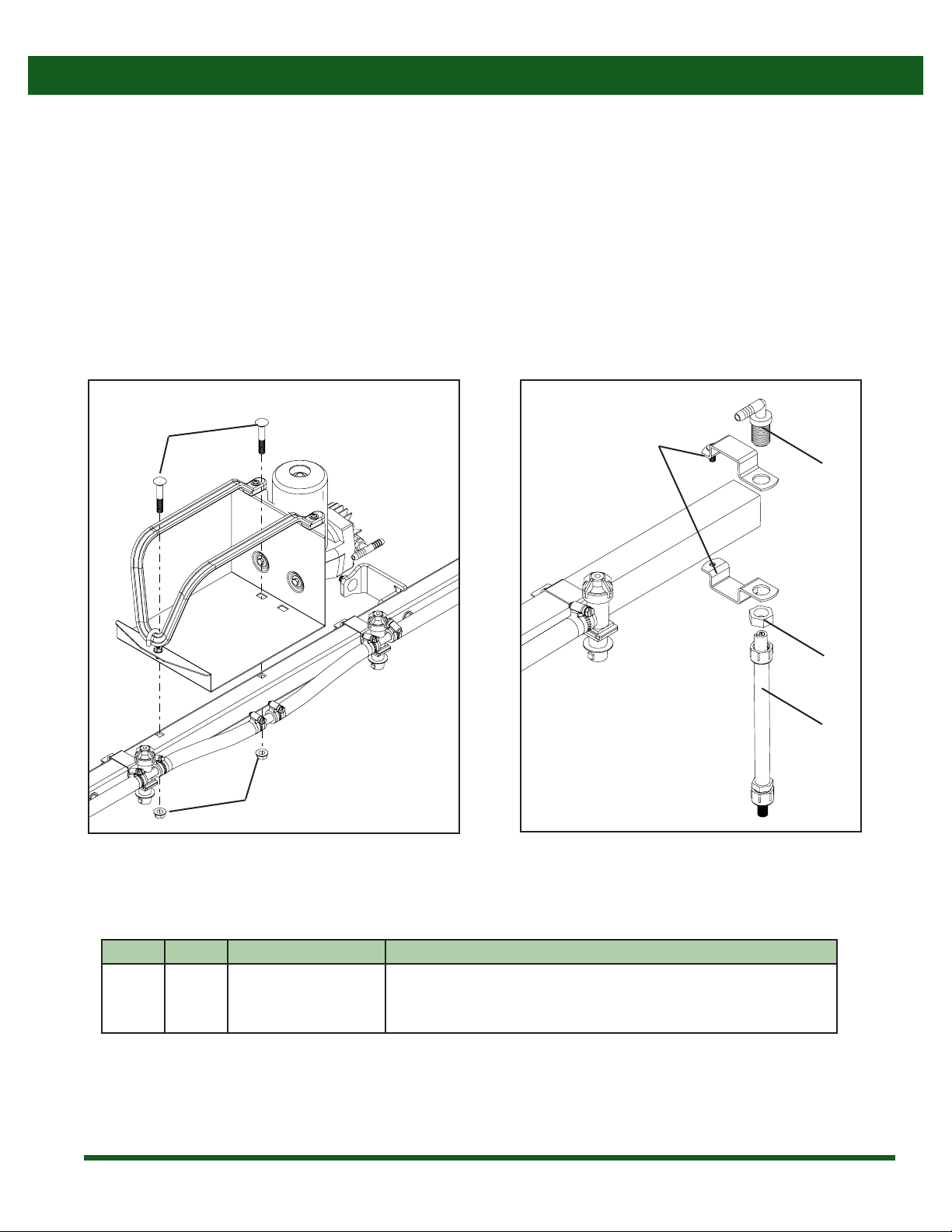
Figure 6: Nozzle assembly
*Included with reference #15 Figure 5: Extension spring mounting
1. Bolt the boom mount brackets (13) (Figure 1 & 3, pg 5 & 6) to
the center frame (1) (Figure 3) using two long carriange bolts
(10) (Figure 1 & 3, pg 5 & 6) and two ange nuts (11) (Figure 1
& 3, pg 5 & 6). Note: The boom mount bracket bent anges
(13) need to be pointed in toward the center of the boom so
that the steel ngers on the brackets slide around the center
frame tube as shown in gure 3.
2. Take the center frame with bolted on boom mount brackets
from step 1 and bolt onto sprayer frame at the desired height
shown in gure 3. Use two carriage bolts (9) (Figure 1 & 3, pg
5 & 6) and two ange nuts (11) (gure 1 & 3, pg 5 & 6).
3. Position the left wing (2) (Figure 4) onto the center frame as
shown in gure 4. Take two long carriage bolts (10) (Figure 1
& 4, pg 5 & 6) and insert them through the hinge plate holes
and center frame holes. Bolt two ange nuts (11) (Figure 1 &
4, pg 5 & 6)onto previously inserted carriage bolts.
4. Bolt at washer (12) and acorn nut (7) (Figure 1 & 5, pg 5 & 6)
onto the vertical wing bolt as shown in gure 5.
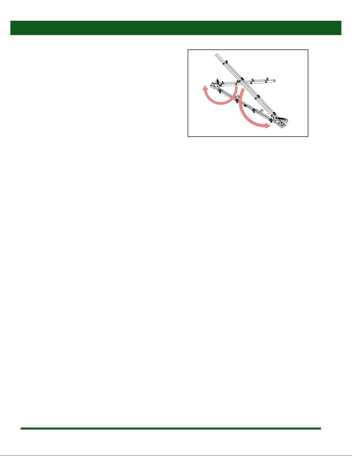
5. Rotate the boom wing towards the center frame to the closed
position.
6. Attach the extension spring (8) (Figure 1 & 5, pg 5 & 6) to the
mounting bracket on the hinge and to the vertical wing bolt
as shown in gure 5 using the washer (12) and acorn nut (7).
7. Install the right boom wing using step 3 through 6.
8. Install nozzle tips onto boom. Insert nozzle tip (16) (Figure 1
& 6, pg 5 & 6) into spray cap (14) (Figure 1 & 6, pg 5 & 6). Then
insert strainer (15) (Figure 1 & 6, pg 5 & 6) into the nozzle body
with the mesh side up. Turn the spray cap onto the nozzle
body. Figure 4: Boom wing mounting
Figure 3: Center frame mounting
ATV-MX240 Assembly Instructions
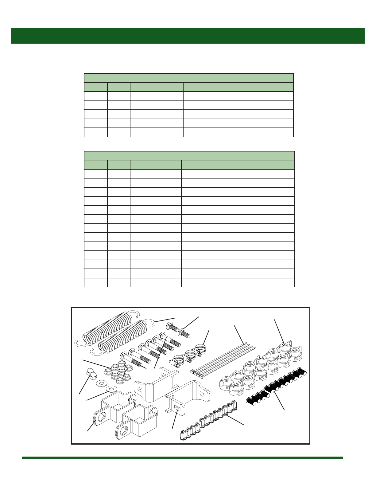
This ATV-MX240 boom kit requires some assembly. Follow the step-by-step instructions to ensure proper assembly. Before assembling,
make sure that all of the necessary components and parts are present as shown in the tables on page 5.
13
13
11
10
10
9
11
12 7
8
10
11
16
14
15
1
2
*

7
Figure 7: Tee/Supply hose
Figure 8: Spray hose installation
Assembly Instructions
9. Connect the hose coming from the controls to the tee on the
center frame as shown in gure 7. Slide a loose hose clamp
(6) (Figure 1 & 7, pg 5 & 7) onto the hose coming from the
controls. Push the hose onto the tee on the center frame.
Tighten the hose clamp around the hose and tee.
10. Connect the wing hoses to the center frame nozzle bodies as
seen in gure 8 & 9. Take the outer wing hose and slide a hose
clamp (6) (Figure 1 & 8, pg 5 & 7) onto it. Route the outer wing
hose through the hose guide hole on the hinge (a) (Figure
9, pg 7). Then push the hose onto the center frame nozzle
body as shown in gure 8. Note: Exerting to much force onto
the nozzle bodies when installing the hoses could potentially
cause them to break.
6
6
Figure 9: Spray hose routing
a

8
Assembly Instructions
***This assembly step is only for assembling an F2500 foam marker kit onto the 20’ manual fold boom. ***
F2500 Foam Marker Kit on ATV-MX240 Assembly Instructions
Figure 1: Mounting foam marker on center frame Figure 2: Mounting drop tubes on outer wings
Ref# Qty. Part Number Description
1 2 CB38*214G5** Bolt, Carriage 3/8-16 x 2-1/4” Gr 5
2 2 FN38** Nut, Flange 3/8-16
3 2 AA111SQ112* Clamp, Square Assembly Boom 1-1/2" Tube
4 2 F2504** Tube, Foam Discharge
1
2
*Included in the HDKMX240 hardware kit.
**Sourced from the F2500 foam marker kit.
1. Bolt foam marker pan onto ATV-MX240 center frame with using the (1) carriage bolts and (2) ange nuts provided in the F2500
foam marker kit.
2. Assemble the (4) drop tubes using the (3) 1 1/2”nozzle body clamps.
3. Route foam marker hoses along boom wings.
3
4
4
4

9
Operating Instructions
1. Unfold the boom by pulling the boom wings toward the
rear of the sprayer as shown (Figure 1). Note: Do not pull
on the boom hoses or nozzle bodies when unfolding, as
this could cause damage to the components.
2. Begin spraying by operating the sprayer’s control
valve(s).
3. When folding the boom, fold the left boom wing rst
until the wing rests against the stop on the hinge.
Then fold the right boom wing to complete the folding
process.
Boom Operation
Figure 1: Unfolding the boom

10
Note: All calibration needs to be done with water only!
When spraying with the boom, the sprayer must be calibrated to ensure proper spray coverage. Before calibrating the sprayer, it is
important to familiarize yourself with the operating instructions. The calibration process is simplied when broken down into the
following steps:
1. Calculate the speed of the sprayer or equipment.
2. Determine the nozzle size and consult the calibration chart for the desired or instructed gallons per acre (GPA).
Calibrating the Sprayer
1. Calculating the Speed
It is important to determine what speed you will be traveling while spraying. Although some tractors may have speedometers,
calculating speed is still recommended for accuracy purposes. To determine the speed follow these four steps:
Note: It is helpful for future references to record the exact RPM and gear used to nd your speed.
1. Measure a 200 foot or 300 foot distance on a eld or a surface similar to where you will be spraying.
2. Drive the equipment and sprayer (half-full is optimal) across the measured distance at a constant rate of speed. There should be
no changes in speed while you are measuring the time. This should be a comfortable speed for spraying.
3. Have someone measure the amount of time (in seconds) it takes to travel the measured distance.
4. Your speed can be calculated by entering your data into the equation Speed (mph) = (Distance (ft) x 60) ÷ (Time (seconds) x 88).
2. Determining Nozzle Size/Using Calibration Chart
The spray nozzles on your sprayer are color-coded to match up with the calibration chart. After you have determined your nozzle
size, you need to look at the calibration chart. Using your calculated speed, nozzle size, and desired gallons per acre (GPA), nd the
pressure (psi) necessary to achieve your GPA. It is important to note that lower pressure settings will result in less spray drift.
Example: Assume you have found your calculated speed to be 5 MPH, your nozzles are lavender (110025), and you want to spray
13 GPA. Upon looking at the chart, you nd that you should set the sprayer's pressure at about 29 psi in order to apply 13 GPA.
Tip Size PSI GPM of one
nozzle
Gallons Per Acre (GPA)
3 MPH 4 MPH 5 MPH 6 MPH
AIXR
(Lavender)
110025
15 0.15 14.8 11.1 8.9 7.4
20 0.18 17.8 13.4 10.7 8.9
30 0.22 21.8 16.3 13.1 10.9
40 0.25 24.8 18.6 14.9 12.4
Please note: Flow rates are calculated using water.

11
Winterizing your Sprayer
It is essential that you winterize your sprayer to avoid damage and to allow for optimal performance. The winterization process
should be undertaken before freezing conditions and/or after each season of use. Failure to winterize your sprayer will void the
manufacturer’s warranty.
Note: Please reference your sprayer owners manual for proper winterizing.
Maintenance Instructions
Routine Maintenance
1. It is recommended to perform a visual and physical inspection for worn parts, loose bolts, damaged hoses, or other visible
problems. Make all necessary repairs before spraying. To order parts or receive technical help, please contact the original
retailer.
2. After each use it is important to rinse the boom and all components by running water through the entire system.
3. Tip strainers should be taken out and rinsed on a regular basis. Tip strainers are the small screens located behind each spray
nozzle on the boom (Figure 6, page 6).
4. Check the amount of grease between the hinge plate and the boom wing. Add grease as needed to keep the wing folding
smoothly and quietly.
It is very important to perform routine maintenance on your sprayer boom before and after each use. Good maintenance practices
will help to guard against any breakdowns or accidents.
Note: Always wear the proper Personal Protective Equipment (PPE) when performing maintenance on your sprayer.
TeeJet®Nozzle Body Breakdown & Parts List
Breakdowns & Parts Lists
Ref # Qty. Part Number Description
1 1 22251311500NYB Elbow body, 1/2” (shown)
- 1 22252312500NYB Tee body, 1/2”
21CP21953EPR* Rubber diaphragm
312195010NYB* Diaphragm cap, 10 psi
3
1
2
Note: Items 2 & 3 are included with Item 1

12
ATV-MX240 Breakdown
Breakdowns & Parts Lists
3
4
5
9
10
11 12
13
14
15
16
2
6
7
8
1
23
24
25
22
21
17
18
19
20
11
14 14
11
26
* Nozzle body breakdown is listed on page 9
Contact an authorized CropCare®dealer for ordering information
27

13
ATV-MX240 Parts List
Breakdowns & Parts Lists
* Nozzle body breakdown is listed on page 9
Contact an authorized CropCare®dealer for ordering information
Ref# Qty. Part Number Description
1 19FT 1208 Hose, EPDM Rubber 1/2" 200 PSI
2 25 6806052 Hose Clamp, 1/2" - 29/32" SS
3 2 22251311500NYB* Body, Nozzle Elbow 1/2" QJ300
4 10 22252312500NYB* Body, Nozzle Tee 1/2" QJ300
5 12 256121NYR Kit, Cap & Gasket Quick TeeJet Black
6 12 8079PP50 Strainer,Tip 50 Mesh Red Poly Body SS Screen
7 12 AIXR110025VP Tip,AIXR TeeJet Polymer Purple
8 2 AN38 Nut,Acorn 3/8-16
9 2 C-267 Spring, Hard Drawn Zinc, 26 lbs/in
10 2 CB38*1G5 Bolt, Carriage 3/8-16 x 1" Gr 5
11 14 CB38*214G5 Bolt, Carriage 3/8-16 x 2-1/4" Gr 5
12 2 CB38*3G5 Bolt, Carriage 3/8-16 x 3" Gr 5
13 2 D-1247 Die Spring, 0.625" rod diameter, 639 lbs max deection force
14 18 FN38 Nut, Flange 3/8-16
15 2 FW38 Washer, Flat 3/8"
16 2 SW58 Washer, Flat 5/8” SAE
17 2 H5C58*412 Bolt, Hex 5/8-11 x 4-1/2" Gr 5
18 1 MX2020 20’ Manual Fold Boom, Center Frame
19 2 MX2021 20’ Manual Fold Boom,Wing
20 4 MX2022 20’ Manual Fold Boom,Wing Support Bracket
21 2 MX2023 20’ Manual Fold Boom, Mount Bracket
22 1 MX2024 20’ Manual Fold Boom, boom hinge, left
23 1 MX2025 20’ Manual Fold Boom, boom hinge, right
24 2 NNC58 Nut, Lock Nylon 5/8-11
25 1 T12 Tee, 1/2" Hose Barbs Nylon
26 12 QJ111SQ112 Clamp, Nozzle Body 1-1/2” Sq Tube Zinc
27 2 875UV Cable Tie, 8” 75 Lb UV Black

14
CropCare®Limited Warranty
Warranty Coverage
Warranty Is Void if:
Getting Service
Manual Fold Boom ATV-MX240
1. The Product has been subjected to, in the opinion of CropCare®, negligent handling, misuse, an accident or if the instructions in
the owner's manual were not completely followed.
2. The Product’s components have been altered in any manner or repairs have taken place with unapproved parts.
3. The Product and its components were subject to freezing or freezing conditions. The Product must have been winterized as per
the maintenance instructions to retain the Product Warranty.
4. A non-compatible chemical was used and/or if the Product operator failed to rinse all chemical residue out of the Product’s
components after use.
5. A petroleum-based, oil-based, or ammable product was used and caused damage to the pump, tank, hoses, or any other
component.
All Product Warranty claims must be made through the original retailer. All warranty claims must be submitted with an invoice or
a proof of purchase that denotes the purchase date and place of purchase. If you have any questions or comments concerning
this warranty, please contact the original retailer.
CropCare® hereby provides a Limited One (1) Year Warranty on the Products manufactured by CropCare® that such Products shall
be free from manufacturer’s defects in any of the Product’s components in the 12 month period following the original date of
purchase from the authorized dealer (the“Warranty Period”). CROPCARE® HEREBY EXCLUDES AND DISCLAIMS ANY AND ALL OTHER
WARRANTIES, STATUTORY, EXPRESS OR IMPLIED, INCLUDING WITHOUT LIMITATION ANY IMPLIED WARRANTY OF MERCHANTABILITY
OR FITNESS FOR ANY PARTICULAR PURPOSE AND ANY WARRANTY ARISING FROM USAGE OF TRADE OR COURSE OF DEALING.
Defective components will be repaired or replaced at the discretion of the manufacturer. It is the responsibility of the purchaser
to return warranted components to the manufacturer. This Product Warranty is limited to the repair or replacement of Product
components only. CROPCARE®IS NOT TO BE HELD LIABLE FOR INCIDENTAL OR CONSEQUENTIAL DAMAGES OF ANY KIND. This
Product Warranty covers the purchaser of this Product and any other owners who own it during Warranty Period.
To retain the Product Warranty, the Product must be operated and maintained as set forth by its owner’s manual. For warranty
service, please have a copy of the purchase invoice available.
Ordering Parts
Please contact the original retailer to order replacement parts for your product.

15
Manufactured by PBZ LLC
A Paul B Zimmerman Inc. Company
www.CropCareEquipment.com
by PBZ
Table of contents
Other PBZ Paint Sprayer manuals