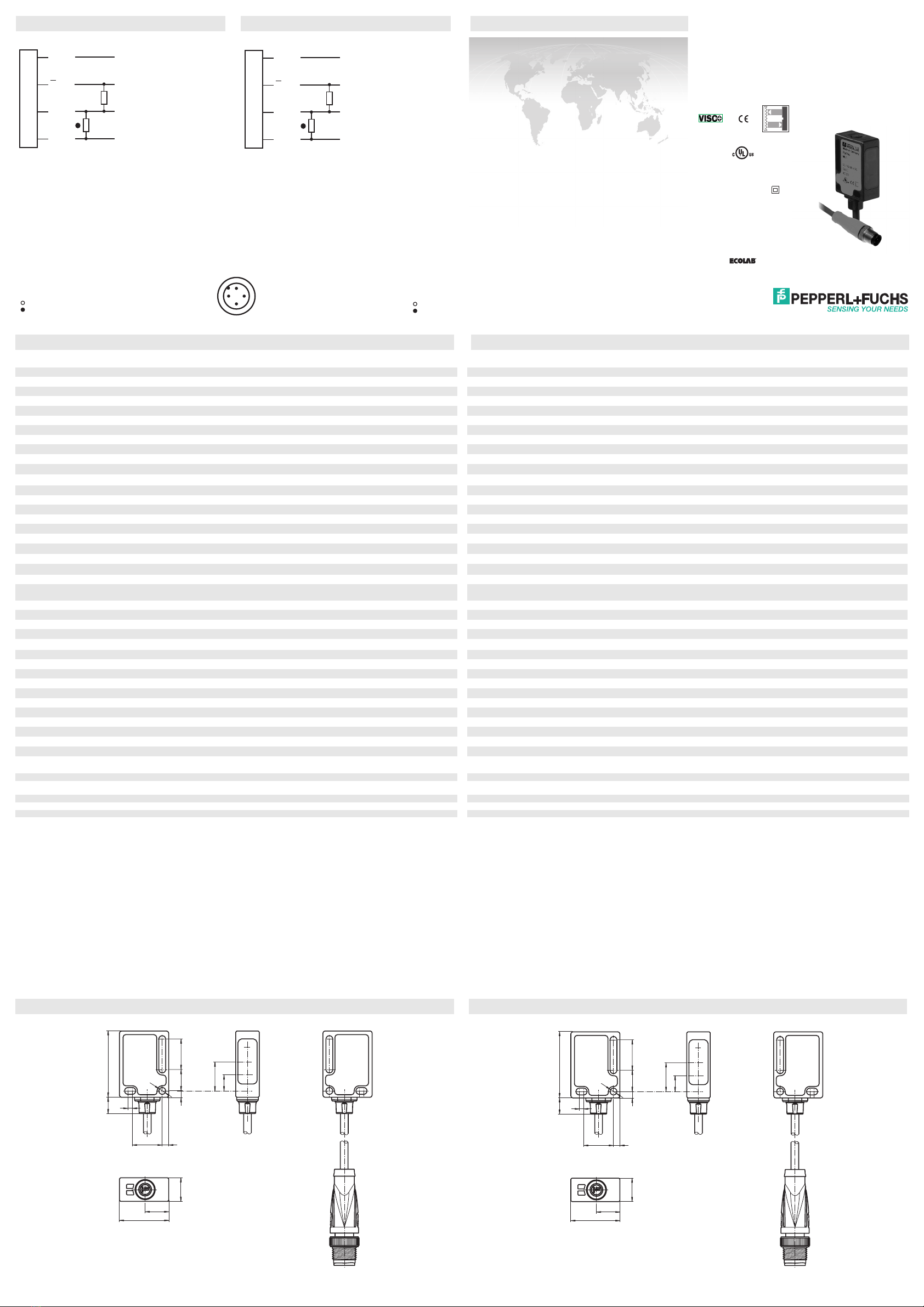
manuals.online logo
Brands
  1. Home
  2. •
  3. Brands
  4. •
  5. Pepperl+Fuchs
  6. •
  7. Accessories
  8. •
  9. Pepperl+Fuchs ML7-55 User manual

Pepperl+Fuchs ML7-55 User manual

alle Maße in mm
DimensionsAbmessungen
Technische Daten Technical data
Elektrischer Anschluss Electrical connection Adressen/Addresses
Sicherheitshinweise:
• Vor der Inbetriebnahme Betriebsanleitung lesen
• Anschluss, Montage und Einstellung nur durch Fachpersonal
• Kein Sicherheitsbauteil gemäß EU-Maschinenrichtlinie
Security Instructions:
• Read the operating instructions before attempting commissioning
• Installation, connection and adjustments should only be undertaken by specialist personnel
• Not a safety component in accordance with the EU Machinery Directive
all dimensions in mm
www.pepperl-fuchs.com
Pepperl+Fuchs GmbH
68301 Mannheim · Germany
Tel. +49 621 776-4411
Fax +49 621 776-27-4411
E-mail: fa-inf[email protected]uchs.com
Worldwide Headquarters
Pepperl+Fuchs GmbH · Mannheim · Germany
E-mail: fa-inf[email protected]uchs.com
USA Headquarters
Pepperl+Fuchs Inc. · Twinsburg · USA
E-mail: fa-info@us.pepperl-fuchs.com
Asia Pacific Headquarters
Pepperl+Fuchs Pte Ltd · Singapore
E-mail: fa-inf[email protected]uchs.com
Company Registration No. 199003130E
103
31
2
14 3
11
11
23
7.5
13.5
14.2
7.6
ø3.2
Reflexions-Lichtschranke
mit 0,2 m Festkabel und M12-Stecker, 4-polig
Retroreflective sensor
with 0.2 m fixed cable and 4-pin, M12 connector
ML7-55/59/82b/103/115b
Allgemeine Daten
Betriebsreichweite 0 ... 3 m
Reflektorabstand 0,03 ... 3 m
Grenzreichweite 3,5 m
Referenzobjekt Reflektor H85-2
Lichtsender LED
Lichtart rot, Wechsellicht
Lichtfleckdurchmesser ca. 180 mm im Abstand von 3,5 m
Öffnungswinkel ca. 3 °
Fremdlichtgrenze 40000 Lux
Kenndaten funktionale Sicherheit
MTTFd1530 a
Gebrauchsdauer (TM) 20 a
Diagnosedeckungsgrad (DC) 0 %
Anzeigen/Bedienelemente
Betriebsanzeige LED grün, blinkend im Kurzschlussfall
Funktionsanzeige LED gelb, leuchtet bei freiem Lichtstrahl, blinkt bei Unterschreiten der Funktionsreserve
Bedienelemente Teach-In-Taste
Elektrische Daten
Betriebsspannung UB10 ... 30 V DC , class 2
Welligkeit max. 10 %
Leerlaufstrom I0< 20 mA
Ausgang
Vorausfallausgang 1 PNP, inaktiv bei Unterschreiten der Funktionsreserve nach ca. 5 s.
Sofort inaktiv, wenn innerhalb der Blinkzeit 4 Strahlunterbrechungen stattfinden.
Schaltungsart dunkelschaltend
Signalausgang 1 PNP-Ausgang, kurzschlussfest, verpolsicher, offener Kollektor
Schaltspannung max. 30 V DC
Schaltstrom max. 100 mA
Spannungsfall Ud
≤
1,5 V DC
Schaltfrequenz f 1000 Hz
Ansprechzeit 0,5 ms
Umgebungsbedingungen
Umgebungstemperatur -20 ... 60 °C (-4 ... 140 °F)
Lagertemperatur -40 ... 75 °C (-40 ... 167 °F)
Mechanische Daten
Schutzart IP67 / IP69K
Anschluss Festkabel 200 mm mit M12-Stecker, 4-polig
Material
Gehäuse PC (Makrolon, glasfaserverstärkt)
Lichtaustritt PMMA
Masse ca. 30 g
Normen- und Richtlinienkonformität
Normenkonformität
Produktnorm EN 60947-5-2:2007
IEC 60947-5-2:2007
Normen EN 50178, UL 508
Zulassungen und Zertifikate
Schutzklasse II, Bemessungsspannung
≤
250 V AC bei Verschmutzungsgrad 1-2 nach IEC 60664-1
UL-Zulassung cULus
103
31
2
14 3
11
11
23
7.5
13.5
14.2
7.6
ø3.2
01/18/2011
Date:
Option:
2
1
3
4
+UB
Q
0 V
Q
Alarm
82b/103
1
3
4
2
General specifications
Effective detection range 0 ... 3 m
Reflector distance 0.03 ... 3 m
Threshold detection range 3.5 m
Reference target H85-2 reflector
Light source LED
Light type modulated visible red light
Diameter of the light spot approx. 180 mm at a distance of 3.5 m
Angle of divergence approx. 3 °
Ambient light limit 40000 Lux
Functional safety related parameters
MTTFd1530 a
Mission Time (TM) 20 a
Diagnostic Coverage (DC) 0 %
Indicators/operating means
Operating display LED green, flashes in case of short-circuit
Function display LED yellow, lights up when light beam is free, flashes when falling short of the stability control
Controls TEACH-IN key
Electrical specifications
Operating voltage UB10 ... 30 V DC , class 2
Ripple max. 10 %
No-load supply current I0< 20 mA
Output
Output of the pre-fault indication 1 PNP, inactive when level falls below function reserve after approx. 5 s.
Immediately inactive if the beam is interrupted 4 times during the flashtime.
Switching type dark on
Signal output 1 PNP output, short-circuit protected, protected from reverse polarity, open collector
Switching voltage max. 30 V DC
Switching current max. 100 mA
Voltage drop Ud
≤
1.5 V DC
Switching frequency f 1000 Hz
Response time 0.5 ms
Ambient conditions
Ambient temperature -20 ... 60 °C (-4 ... 140 °F)
Storage temperature -40 ... 75 °C (-40 ... 167 °F)
Mechanical specifications
Protection degree IP67 / IP69K
Connection fixed cable 200 mm with M12 connector, 4-pin
Material
Housing PC (glass-fiber-reinforced Makrolon)
Optical face PMMA
Mass approx. 30 g
Compliance with standards and directives
Standard conformity
Product standard EN 60947-5-2:2007
IEC 60947-5-2:2007
Standards EN 50178, UL 508
Approvals and certificates
Protection class II, rated voltage
≤
250 V AC with pollution degree 1-2 according to IEC 60664-1
UL approval cULus
= Hellschaltung
= Dunkelschaltung
= Light on
= Dark on
Option:
2
1
3
4
+UB
Q
0 V
Q
Alarm
82b/103
DIN A3 -> DIN A7
Part. No.: 128755 45-0800B
Doc. No.:
Bestimmungsgemäße Verwendung:
Eine Reflexionslichtschranke enthält Sender und Empfänger in einem Gehäuse. Das Licht des Senders wird von einem Reflektor zum
Empfänger zurückgestrahlt. Bei Unterbrechung des Lichtstrahls durch ein Objekt wird die Schaltfunktion ausgelöst.
Montagehinweise:
Die Sensoren können über Durchgangsbohrungen direkt oder über einen Haltewinkel befestigt werden. (diese sind nicht im Lieferumfang
enthalten).
Die Untergrundfläche muss plan sein, um Gehäuseverzug beim Festziehen zu vermeiden.
Es empfiehlt sich, die Mutter und Schraube mit Federscheiben zu sichern, um einer Dejustierung des Sensors vorzubeugen.
TEACH-IN
Nach Anlegen der Betriebsspannung leuchtet die LED grün. Der Sensor ist automatisch im Zustand max. Empfindlichkeit (Auslieferungs-
zustand) bzw. im Zustand der letzten TEACH-IN Einstellung.
Montieren Sie den geeigneten Reflektor gegenüber der Lichtschranke
• Den Sensor auf den Reflektor ausrichten.
• TEACH-IN Taste drücken - zur Bestätigung geht die grüne LED-Anzeige einmal kurz aus.
• TEACH-IN Taste solange gedrückt halten bis die gelbe und grüne Anzeige-LED parallel blinken (2Hz). Danach die TEACH-IN Taste
loslassen.
• Während des internen Set-Up des Sensors blinken die grüne und gelbe LED-Anzeige abwechselnd (2Hz).
•TEACH-IN erfolgreich: Die grüne und gelbe Anzeige-LED leuchten. Das Gerät ist betriebsbereit und befindet sich im Schaltzustand.
•TEACH-IN nicht erfolgreich: Beide LED-Anzeigen blinken schnell, abwechselnd (4Hz) für ca. 5 Sekunden. Der Sensor geht in den
Zustand max. Empfindlichkeit. Danach die TEACH-IN Prozedur wiederholen, beginnend bei Schritt 1.
Kontrolle Objekterfassung
Das Objekt in den Strahlengang bringen. Wird das Objekt erfasst, erlischt die gelbe LED.
Nach Entfernen des Objektes leuchtet die Anzeige-LED gelb wieder konstant.
Reinigung:
Bei Verschlechterung des Empfangs (Verschmutzung) blinkt die gelbe LED.
Deshalb empfehlen wir in regelmäßigen Abständen die Optikfläche zu reinigen und
Verschraubungen, sowie die Anschlussverbindungen zu überprüfen.
Conventional use
The reflex light beam switch contains the emitter and receiver in a single housing. The light from transmitter is beamed back from a re-
flector to the receiver. If an object interrupts the light beam the switching function is initiated.
Mounting instructions
The sensor can be fastened over the through-holes directly or with a support angle (this are not contained in the scope of supply).
The base surface must be flat to avoid distorting the housing during mounting. It is advisable to secure the bolts and screws with washers
to prevent misalignment.
TEACH-IN
Connect the sensor to operating voltage, the LED green lights up constantly. The sensor operates at max. sensitivity (delivery status) or
with the last teached values.
Mount suitable reflector opposite light beam switch.
• Adjust the unit to the reflector.
• Press the TEACH-IN button - as an acknowledge the green LED will switch off shortly for one time.
• Press the TEACH-IN button until both LEDs green and yellow are blinking in parallel (2Hz). Release the TEACH-IN button now.
• While the green and yellow LEDs are blinking alternating (2Hz) the unit is in the internal set up procedure.
•TEACH-IN successful: Both LEDs green and yellow are on. The unit is ready to use and in switching mode now.
•TEACH-IN not successful: Both LEDs are flashing alternating (4Hz) for approx. 5 seconds. Afterwards the sensor returns to max. sen-
sitivity setting. Please retry the TEACH-IN procedure beginning by step 1.
Object detection check
Move the object into the light beam. If the object is recorded, the yellow LED switch off.
It should lights up constantly on again when the object is removed.
Lustration
The yellow LED flashes if reception deteriorates (e.g. soiled lenses.)
We recommend that you clean the optical interfaces and check the plug- and screw connections at regular intervals.
Anzeigen/Bedienelemente
Indicators/operating means
1 Betriebsanzeige grün
2 Signalanzeige gelb
3 TEACH-IN-Taste
4 Sender
5 Empfänger
123452
1 Operating display green
2 Signal display yellow
3 TEACH-INbutton
4 Emitter
5 Receiver
123452
0 0.5 1.0 1.5 2.0 2.5 3.0
120
100
80
60
40
20
0
X [m]
Y [mm] ML7(1)-55
x
y
H85-2
C110-2
H60
H160
OFR-100/100
Charakteristische Ansprechkurve
Courbe de response caractéristique
Curve di risposta caratteristica
Characteristic response curve
Curva de respuesta característica
Möglicher Abstand (Versatz) zwischen
optischer Achse und Referenzobjekt.
Permissible distance (offset) between
optical axis and reference target.
Ecart possible entre l'axe optique et la
cible de référence.
Desplazamiento entre el eje óptico y
objeto de referencia.
Distanza possibile (sfalsato) tra l'asse
ottico e l'ogetto di riferimento.
100.0
10.0
1.0
0.1
0.0 0.5 1.0 1.5 2.0 2.5 3.0 3.5
1.5
Funktionsreserve, Stability control, Réserve de fonctionnement,
Reserva de función, Funzione riserva
ML7(1)-55
x
H160
H85-2
H60
C110-2
OFR-100/100
Relative Empfangslichtstärke
Intensité relative de la lumière reçue
Intensità relativa luce in ricezione
Relative received light strength
Potencia relativa de recepción lumínica
x [m]
Beschreibung/Desciption

This manual suits for next models

4

Other Pepperl+Fuchs Accessories manuals

Pepperl+Fuchs GLV18-55-G/25/102/115 User manual

Pepperl+Fuchs

Pepperl+Fuchs GLV18-55-G/25/102/115 User manual

Pepperl+Fuchs PHA Series User manual

Pepperl+Fuchs

Pepperl+Fuchs PHA Series User manual

Pepperl+Fuchs UC6000-30GM70-2E2R2-V15 User manual

Pepperl+Fuchs

Pepperl+Fuchs UC6000-30GM70-2E2R2-V15 User manual

Pepperl+Fuchs MLV41-8-HV-60-IR/110/124/167 User manual

Pepperl+Fuchs

Pepperl+Fuchs MLV41-8-HV-60-IR/110/124/167 User manual

Pepperl+Fuchs LUC-M Series Parts list manual

Pepperl+Fuchs

Pepperl+Fuchs LUC-M Series Parts list manual

Pepperl+Fuchs RLK28-55/31/116 User manual

Pepperl+Fuchs

Pepperl+Fuchs RLK28-55/31/116 User manual

Pepperl+Fuchs 6GR6241-7BB00-PF User manual

Pepperl+Fuchs

Pepperl+Fuchs 6GR6241-7BB00-PF User manual

Pepperl+Fuchs UC2000-L2-E7-V15 User manual

Pepperl+Fuchs

Pepperl+Fuchs UC2000-L2-E7-V15 User manual

Pepperl+Fuchs LUC-M10 Installation instructions

Pepperl+Fuchs

Pepperl+Fuchs LUC-M10 Installation instructions

Pepperl+Fuchs UC F77 Series User manual

Pepperl+Fuchs

Pepperl+Fuchs UC F77 Series User manual

Pepperl+Fuchs NJ15-30GM50-E2-V1-3G-3D User manual

Pepperl+Fuchs

Pepperl+Fuchs NJ15-30GM50-E2-V1-3G-3D User manual

Pepperl+Fuchs UC2000-L2-E6-V15-Y277310 User manual

Pepperl+Fuchs

Pepperl+Fuchs UC2000-L2-E6-V15-Y277310 User manual

Pepperl+Fuchs VIM6 Series User manual

Pepperl+Fuchs

Pepperl+Fuchs VIM6 Series User manual

Pepperl+Fuchs INY360D-F99-2I2E2-V17 User manual

Pepperl+Fuchs

Pepperl+Fuchs INY360D-F99-2I2E2-V17 User manual

Pepperl+Fuchs OMD8000-R300-UEP-V1-L User manual

Pepperl+Fuchs

Pepperl+Fuchs OMD8000-R300-UEP-V1-L User manual

Pepperl+Fuchs NBN4-12GS40-Z4L-V1-3G-3D User manual

Pepperl+Fuchs

Pepperl+Fuchs NBN4-12GS40-Z4L-V1-3G-3D User manual

Pepperl+Fuchs RAVE-D-NA User manual

Pepperl+Fuchs

Pepperl+Fuchs RAVE-D-NA User manual

Pepperl+Fuchs UDCM-30GS Series Installation and operation manual

Pepperl+Fuchs

Pepperl+Fuchs UDCM-30GS Series Installation and operation manual

Pepperl+Fuchs UC500-L2-E7-V15 Operating instructions

Pepperl+Fuchs

Pepperl+Fuchs UC500-L2-E7-V15 Operating instructions

Pepperl+Fuchs SmartRunner Matcher User manual

Pepperl+Fuchs

Pepperl+Fuchs SmartRunner Matcher User manual

Pepperl+Fuchs PHA-F200-R3 Series User manual

Pepperl+Fuchs

Pepperl+Fuchs PHA-F200-R3 Series User manual

Pepperl+Fuchs VDM70 Series User manual

Pepperl+Fuchs

Pepperl+Fuchs VDM70 Series User manual

Pepperl+Fuchs SJ2-SN User manual

Pepperl+Fuchs

Pepperl+Fuchs SJ2-SN User manual

Pepperl+Fuchs ML300-P-6m-RT/25 User manual

Pepperl+Fuchs

Pepperl+Fuchs ML300-P-6m-RT/25 User manual

Popular Accessories manuals by other brands

Quincy lab 140AE-1 operating manual

Quincy lab

Quincy lab 140AE-1 operating manual

HomePro ZIR000 user manual

HomePro

HomePro ZIR000 user manual

DOL 20SCR Technical user guide

DOL

DOL 20SCR Technical user guide

RAB Smart Task installation manual

RAB

RAB Smart Task installation manual

Kemppi KMS 300 quick guide

Kemppi

Kemppi KMS 300 quick guide

Stearns 57,500 Series Installation and service instructions

Stearns

Stearns 57,500 Series Installation and service instructions

iGuzzini TWILIGHT COPENAGHEN manual

iGuzzini

iGuzzini TWILIGHT COPENAGHEN manual

Adelaide Annexe & Canvas Avan Deluxe installation guide

Adelaide Annexe & Canvas

Adelaide Annexe & Canvas Avan Deluxe installation guide

OHAUS 5000 instruction manual

OHAUS

OHAUS 5000 instruction manual

HOME8 WLS1300 quick start guide

HOME8

HOME8 WLS1300 quick start guide

MAXBOTIX MaxSonar quick start guide

MAXBOTIX

MAXBOTIX MaxSonar quick start guide

ioSmart iSmart56 Installation and user guide

ioSmart

ioSmart iSmart56 Installation and user guide

Focusrite Scarlett 18i8 user guide

Focusrite

Focusrite Scarlett 18i8 user guide

Velleman ED38105 user manual

Velleman

Velleman ED38105 user manual

JumpSport SkyBounce user manual

JumpSport

JumpSport SkyBounce user manual

Prima-Temp PRIYA Instructions for use

Prima-Temp

Prima-Temp PRIYA Instructions for use

Tefcold BC85I-BC85I W user manual

Tefcold

Tefcold BC85I-BC85I W user manual

Vaisala WMS302 user guide

Vaisala

Vaisala WMS302 user guide

manuals.online logo
manuals.online logoBrands
  • About & Mission
  • Contact us
  • Privacy Policy
  • Terms and Conditions

Copyright 2025 Manuals.Online. All Rights Reserved.