manuals.online logo
Brands
  1. Home
  2. •
  3. Brands
  4. •
  5. Pepperl+Fuchs
  6. •
  7. Industrial Equipment
  8. •
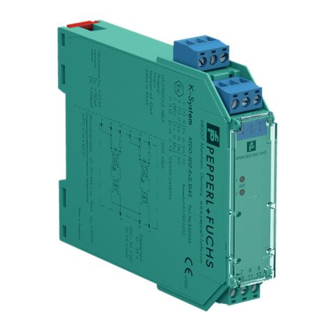
  9. Pepperl+Fuchs KCDO-LGH User manual

Pepperl+Fuchs KCDO-LGH User manual

Subject to modifications without notice
Pepperl+Fuchs Group
www.pepperl-fuchs.com
USA: +1 330 486 0002
[email protected] [email protected]
Singapore: +65 6779 9091
[email protected]
Copyright Pepperl+Fuchs
Germany: +49 621 776 2222
DOCT-1723 02/2009
1
Operatin
g
Instructions
Place Holder Barrier – K-System
Versions
Safety information
The corresponding data sheets and the declaration of
conformity are an integral part of this document.
Intended use
Laws and regulations applicable to the usage or planned
purpose of usage must be observed. Devices are only
approved for proper usage in accordance with intended use.
Improper handling will result in voiding of any warrantee or
manufacturer's responsibility.
The devices are not suitable for the isolation of signals in
power engineering.
Protection of operating personnel and the system is not
ensured if the product is not used in accordance with its
intended use.
Installation and commissioning
Commissioning and installation must be carried out by
specially trained and qualified personnel only.
Installation of the interface devices in the
safe area
The devices are constructed to satisfy the IP20 protection
classification and must be protected from adverse
environmental conditions such as water spray or dirt
exceeding the pollution degree 2.
The devices must be installed outside the hazardous area!
The installation of the intrinsically safe circuits is to be
conducted in accordance with the relevant installation
regulations. It is especially important to ensure that all non-
intrinsically safe circuits are safely isolated (see section
"Internal connections").
The respective peak values of the field device and the
associated device with regard to explosion protection should
be considered when connecting intrinsically safe field devices
with the intrinsically safe circuits of devices (demonstration of
intrinsic safety). EN 60079-14/IEC 60079-14 is to be observed
(where appropriate). The K*D0-LGH* is passive, the
intrinsically safe data corresponds to that in the connected
devices.
When connecting several intrinsically safe current circuits,
these current circuits are to be considered as connected.
Installation and commissioning of the
interface devices within Zone 2/Div. 2 of the
hazardous area
Only devices with the corresponding manufacturer's
declaration of conformity or separate certificate of conformity
can be installed in Zone 2/Div. 2.
The individual data sheets indicate whether these conditions
are met.
The devices should be installed in a switch or junction box that:
• meets at least IP54 in accordance to EN 60529.
• meets to the requirements of resistance to light and
resistance to impact according to EN 60079-0/
IEC 60079-0.
• meets to the requirements of thermal endurance according
to EN 60079-15/IEC 60079-15.
• must not cause ignition danger by electrostatic charge
during intended use, maintenance and cleaning.
The installation of the intrinsically safe circuits is to be
conducted in accordance with the relevant installation
regulations. It is especially important to ensure that all non-
intrinsically safe circuits are safely isolated (see section
"Internal connections").
The respective peak values of the field device and the
associated device with regard to explosion protection should
be considered when connecting intrinsically safe field devices
with the intrinsically safe circuits of devices (demonstration of
intrinsic safety). EN 60079-14/IEC 60079-14 is to be observed
(where appropriate). The K*D0-LGH* is passive, the
intrinsically safe data corresponds to that in the connected
devices.
When connecting several intrinsically safe current circuits,
these current circuits are to be considered as connected.
The manufacturer's declaration of conformity should be
observed. It is especially important to observe the "special
conditions" if these are included in the certificates.
Repair and maintenance
Maintenance is not required.
Fault elimination
Only those changes that are listed in the section "Internal
connections" may be performed on devices that are operated
in connection with hazardous areas. Repairs to a device may
also only be performed at these locations.
KCD0-LGH empty housing, internal connection via
jumpers possible, for intrinsically safe
and non-intrinsically safe circuits
KFD0-LGH empty housing, internal connection via
jumpers possible, for intrinsically safe
and non-intrinsically safe circuits
KFD0-LGH-5T empty housing, internal connection via
jumpers possible, for intrinsically safe
and non-intrinsically safe circuits,
5terminals
KFD0-LGH-Y34868 empty housing, no internal connection
possible
KFD0-LGH-Y39343 empty housing, internal connection via
DIP switches possible, for intrinsically
safe and non-intrinsically safe circuits
KFD0-LGH-GN empty housing, internal connection via
jumpers possible, only for intrinsically
safe circuits
Subject to modifications without notice
Pepperl+Fuchs Group
www.pepperl-fuchs.com
USA: +1 330 486 0002
[email protected] [email protected]
Singapore: +65 6779 9091
[email protected]
Copyright Pepperl+Fuchs
Germany: +49 621 776 2222
DOCT-1723 02/2009
2
Operatin
g
Instructions
Place Holder Barrier – K-System
Isolation coordinates for installations for
galvanic isolation according to EN 50178
and EN 61140 or EN 60079-11
The devices are built-in devices or electronic equipment for
use in secluded electrical operating sites where only skilled
personnel or electrically instructed personnel will have
admission or access.
The devices are assessed for pollution degree 2 and
overvoltage category II according to EN 50178.
No insulation is present within terminals 1 to 4 and 5 to 8 of the
KCD0-LGH and/or within terminals 1 to 6 and 7 to 15 of the
KFD0-LGH*.
Terminals 1 to 4 of KCD0-LGH are galvanically isolated from
terminals 5 to 10 and/or terminals 1 to 6 of
KFD0-LGH* from terminals 7 to 15 in accordance with
EN 50178/IEC 62103 up to a voltage of 300 Vrms and/or. in
accordance with EN 60079-11/IEC 60079-11 up to a peak
value of the rated voltage of 375 V. This applies only if the
internal connections are designed appropriately (see section
"Internal connections").
Technical data
Electrical data
Non-intrinsically safe circuits
• Voltage within the circuit ≤50 V
• Current per channel ≤2A
• Current per channel with common lead ≤1A
Intrinsically safe circuits
• Voltage within the circuit ≤40 V
• Current per channel ≤2A
• Current per channel with common lead ≤1A
Mechanical data
Mounting
• Snap-on 35 mm standard DIN rail acc. to EN 60715. Can
be mounted horizontally or vertically, side by side.
• Panel mount: The lugs on the base of the modules must be
extended and used for mounting purposes with 3 mm
screws.
• K-MS mounting base for screw attachment
Housing material
Polycarbonate (PC)
Protection degree
IP20 acc. to EN 60529
Connection
removable connector with integrated self opening device
terminals for leads of up to a max. of 1 x 2.5 mm2(14 AWG)
Ambient conditions
Ambient temperature
-20 °C to 60 °C (253 K to 333 K)
Storage temperature
-40 °C to 90 °C (233 K to 363 K)
Relative humidity
max. 95 % without moisture condensation
Vibration resistance
acc. to EN 60068-2-6, 10 Hz to 150 Hz, 1 g, high crossover
frequency
Shock resistance
acc. to EN 60068-2-27, 15 g, 11 ms, half-sine
Internal connections
Soldering may be performed only at the locations intended for
this purpose.
Galvanic isolation of terminals 1 to 4 of the KCD0-LGH to
terminals 5 to 10 and/or terminals 1 to 6 of the
KFD0-LGH* to terminals 7 to 15 is only present if one of the
following conditions is met:
• The device corresponds to a device with the order code
mentioned at the beginning and no modifications were
made to the device.
• The device corresponds to a device with the order code
mentioned at the beginning, only the DIP switch was
activated and no modifications were made to the device.
• Connections were soldered, which all correspond to the
following:
– Connections only within terminals 1 to 4 and within
terminals 5 to 10 of the KCD0-LGH and/or only within
terminals 1 to 6 and within terminals 7 to 15 of the
KFD0-LGH* and no connection was made between
these terminal groups.
– Distance between the conductive part of terminals 1
to 4 and the conductive part of terminals 5 to 10 of the
KCD0-LGH and/or the distance between the
conductive part of terminals 1 to 6 and the conductive
part of terminals 7 to 15 of the KFD0-LGH* > 10 mm.
– The wire has a diameter of > 0.5 mm and is not longer
than 50 mm.
– The wire is fed through the printed circuit board and
bent before soldering.

This manual suits for next models

5

Other Pepperl+Fuchs Industrial Equipment manuals

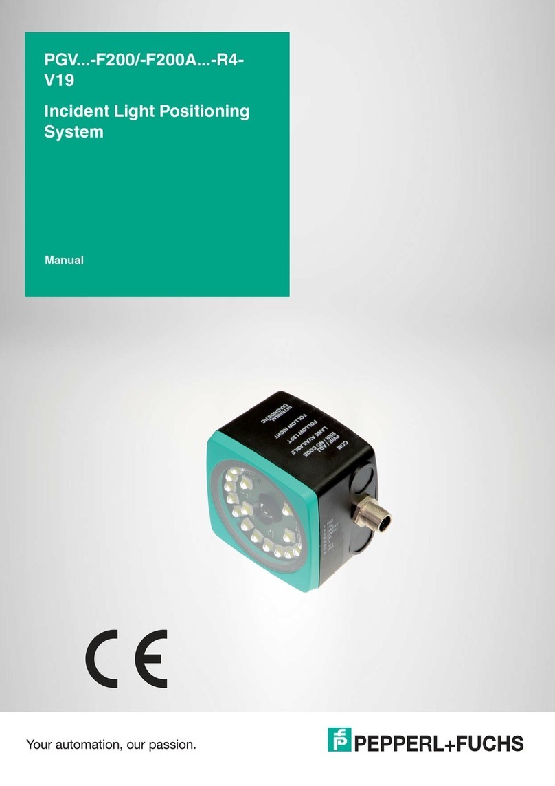
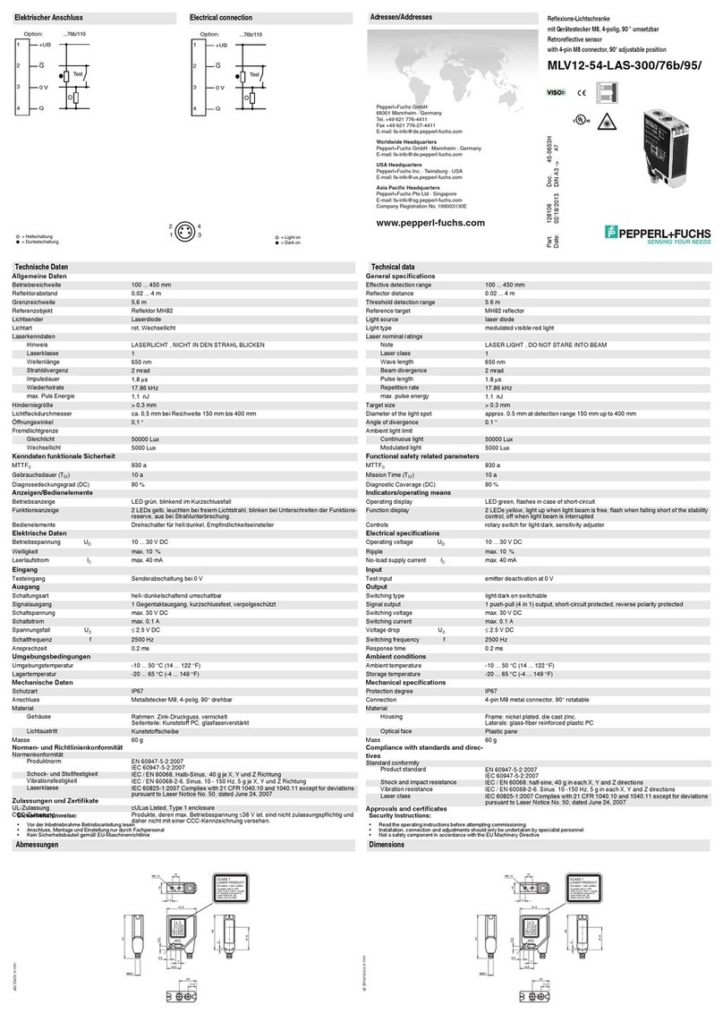
Pepperl+Fuchs IQT-F116-R4-V1 User manual

Pepperl+Fuchs

Pepperl+Fuchs IQT-F116-R4-V1 User manual

Pepperl+Fuchs PGV Series User manual

Pepperl+Fuchs

Pepperl+Fuchs PGV Series User manual

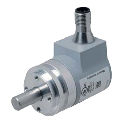
Pepperl+Fuchs 6000 SERIES User manual

Pepperl+Fuchs

Pepperl+Fuchs 6000 SERIES User manual

Pepperl+Fuchs PGV F200A User manual

Pepperl+Fuchs

Pepperl+Fuchs PGV F200A User manual

Pepperl+Fuchs KT-SRT-FF User manual

Pepperl+Fuchs

Pepperl+Fuchs KT-SRT-FF User manual

Pepperl+Fuchs KFD2-CD-1.32 Series User manual

Pepperl+Fuchs

Pepperl+Fuchs KFD2-CD-1.32 Series User manual

Pepperl+Fuchs EI-0D2-10Y-10B-LT User manual

Pepperl+Fuchs

Pepperl+Fuchs EI-0D2-10Y-10B-LT User manual

Pepperl+Fuchs 6500 Series User manual

Pepperl+Fuchs

Pepperl+Fuchs 6500 Series User manual

Pepperl+Fuchs PXV80AQS-F200-R4-V19 User manual

Pepperl+Fuchs

Pepperl+Fuchs PXV80AQS-F200-R4-V19 User manual

Pepperl+Fuchs DAD10-8P Series User manual

Pepperl+Fuchs

Pepperl+Fuchs DAD10-8P Series User manual

Pepperl+Fuchs FD0-VC-Ex4.FF User manual

Pepperl+Fuchs

Pepperl+Fuchs FD0-VC-Ex4.FF User manual

Pepperl+Fuchs 7500 Series User manual

Pepperl+Fuchs

Pepperl+Fuchs 7500 Series User manual

Pepperl+Fuchs 1001A Series User manual

Pepperl+Fuchs

Pepperl+Fuchs 1001A Series User manual

Pepperl+Fuchs 1001B Series User manual

Pepperl+Fuchs

Pepperl+Fuchs 1001B Series User manual

Pepperl+Fuchs PXV100AQ-F200-R4-V19 User manual

Pepperl+Fuchs

Pepperl+Fuchs PXV100AQ-F200-R4-V19 User manual

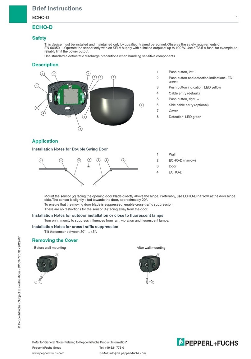
Pepperl+Fuchs ECHO-D Reference guide

Pepperl+Fuchs

Pepperl+Fuchs ECHO-D Reference guide

Pepperl+Fuchs RSD-CFA-CN User manual

Pepperl+Fuchs

Pepperl+Fuchs RSD-CFA-CN User manual

Pepperl+Fuchs PGV -F213-B16-1.5M Series User manual

Pepperl+Fuchs

Pepperl+Fuchs PGV -F213-B16-1.5M Series User manual

Pepperl+Fuchs FieldConnex D0-TI-Ex8 Series User manual

Pepperl+Fuchs

Pepperl+Fuchs FieldConnex D0-TI-Ex8 Series User manual

Pepperl+Fuchs PCV F200-R4-V19 Series User manual

Pepperl+Fuchs

Pepperl+Fuchs PCV F200-R4-V19 Series User manual

Pepperl+Fuchs VisuNet TCU1100 Series User manual

Pepperl+Fuchs

Pepperl+Fuchs VisuNet TCU1100 Series User manual

Pepperl+Fuchs VisuNet Control Center 6 User manual

Pepperl+Fuchs

Pepperl+Fuchs VisuNet Control Center 6 User manual

Pepperl+Fuchs PGV100RS-F200-B16-1,5M User manual

Pepperl+Fuchs

Pepperl+Fuchs PGV100RS-F200-B16-1,5M User manual

Pepperl+Fuchs BEBCO EPS 1002 User manual

Pepperl+Fuchs

Pepperl+Fuchs BEBCO EPS 1002 User manual

Popular Industrial Equipment manuals by other brands

ABB HT842718 Operation manual

ABB

ABB HT842718 Operation manual

probst TSV operating instructions

probst

probst TSV operating instructions

Fein FRIT GIB quick start guide

Fein

Fein FRIT GIB quick start guide

probst FVZ-UNI operating instructions

probst

probst FVZ-UNI operating instructions

Tormach 35550 Technical document

Tormach

Tormach 35550 Technical document

ABB HT576398 Operation manual

ABB

ABB HT576398 Operation manual

JUKI KE-2050 Maintenance Guide

JUKI

JUKI KE-2050 Maintenance Guide

CyBe Construction 3DP 1.0 Operator's manual

CyBe Construction

CyBe Construction 3DP 1.0 Operator's manual

Graco Therm-O-Flow 20 Instructions - parts

Graco

Graco Therm-O-Flow 20 Instructions - parts

Trooper ADVANTAGE TR-100 instruction manual

Trooper

Trooper ADVANTAGE TR-100 instruction manual

Gigola HURRICANE Series Assembly instructions

Gigola

Gigola HURRICANE Series Assembly instructions

Aerotech ABL2000 Series user manual

Aerotech

Aerotech ABL2000 Series user manual

Nordson ColorMax Series manual

Nordson

Nordson ColorMax Series manual

MATO pneuMATO 55 Lube-Jet operating instructions

MATO

MATO pneuMATO 55 Lube-Jet operating instructions

Telesis FQ20 manual

Telesis

Telesis FQ20 manual

Progres AGRONIC 4000 instruction manual

Progres

Progres AGRONIC 4000 instruction manual

HOLZMANN MASCHINEN UFE410FLEX user manual

HOLZMANN MASCHINEN

HOLZMANN MASCHINEN UFE410FLEX user manual

ADT 8020 Maintenance manual

ADT

ADT 8020 Maintenance manual

manuals.online logo
manuals.online logoBrands
  • About & Mission
  • Contact us
  • Privacy Policy
  • Terms and Conditions

Copyright 2025 Manuals.Online. All Rights Reserved.