IMT 3203i Use and care manual

Printed on 12 February, 2007
# 99903618
IMT Electric-Hydraulic Crane
Operation & Safety Manual
(Models 3203i, 4004i, & 6006i)
20070212
IOWA MOLD TOOLING CO., INC.
PO Box 189
Garner, IA 50438
Tel: 641-923-3711 FAX: 641-923-2424
Website: http://www.imt.com
Copyright © 2007 Iowa Mold Tooling Co., Inc.
All rights reserved
No part of this publication may be reproduced, stored in a retrieval system, or transmitted in any
form or by any means, electronic, mechanical, photocopying, recording or otherwise without the
prior written permission of Iowa Mold Tooling Co., Inc.
Iowa Mold Tooling Co., Inc. is an Oshkosh Truck Corporation Company.


i
Contents
Revisions ..................................................................................................................................................... ii
Introduction 3
Operation 5
Safety............................................................................................................................................................6
Crane Component Identification...................................................................................................................8
General..........................................................................................................................................................9
Daily Safety Inspection.................................................................................................................................9
Electrical Hazards.......................................................................................................................................10
Crane Capacity............................................................................................................................................12
Load Ratings...............................................................................................................................................13
Capacity Chart.................................................................................................................................14
Outriggers ...................................................................................................................................................15
Initial Operation..........................................................................................................................................15
Crane Operation..........................................................................................................................................15
Overload Protection System ............................................................................................................17
Anti-Two-Block System..................................................................................................................18
Operation in Adverse Conditions................................................................................................................18
Cold Weather...................................................................................................................................18
Hand Signals...............................................................................................................................................20

ii Contents
Revisions
DATE LOCATION DESCRIPTION
20050830 MODEL CHANGES TO 3203i, 4004i, AND 6006i

3
GENERAL
The information contained in this manual is designed to help provide you with the knowledge
necessary in the safe and proper operation of your IMT crane. This information is not intended to
replace any governmental regulations, safety codes or insurance carrier requirements.
Operators, maintenance and test personnel must read and understand all safety procedures
applicable to the equipment in use.
WARNING
FAILURE TO READ, UNDERSTAND AND FOLLOW ANY SAFETY PROCEDURES
APPLICABLE TO YOUR EQUIPMENT MAY RESULT IN EQUIPMENT DAMAGE, SERIOUS
INJURY, OR DEATH.
In addition to reading the manual, it is your responsibility to become familiar with government
regulations, hazards, and the specific operation of your crane. Use caution and common sense
while operating and maintaining the crane, and follow all safety procedures and regulations.
Refer to ANSI/ASME B30.5, the standard for Telescoping and Mobile Boom Cranes, for more
information on crane design and test criteria. (You may obtain this publication from the
American Society of Mechanical Engineers at www.asme.org.) Crane operators must also be
familiar with OSHA 29CFR, Subpart N, Article 1926.550 and CAL-OSHA Title 8, Article 93
(California).
CRANE AND SAFETY EQUIPMENT MODIFICATIONS
Modifications to your crane must be performed with IMT approved accessories, parts and
optional equipment. If in doubt about the safety, compatibility, or appropriateness of any
modifications, contact IMT prior to making those modifications. DO NOT alter or modify any
safety device! All safety devices must be inspected, tested and maintained in proper working
condition.
Decals regarding crane safety and operation are considered to be safety equipment. They must
be maintained just as any other safety device. Decals must be kept clean and legible to the
operator, operational personnel, and bystanders as specified in the decal section of this manual.
DO NOT remove, disable, or disregard any safety device attached to your crane.
OWNER RESPONSIBILITIES
It is the user’s responsibility to maintain and operate this unit in a manner that will result in the
safest working conditions possible, and to be aware of existing Federal, State, and Local codes
and regulations governing the safe use and maintenance of this unit.
CHAPTER 1
Introduction

4 IMT Electric-Hydraulic Crane Operation & Safety Manual # 99903618
The owner and/or designated employee is responsible for informing all operators, maintenance
personnel, and others involved in equipment operation about the safe operation and
maintenance of the crane. If questions arise concerning safe crane operation, contact IMT or
your IMT distributor for clarification.
MANUAL STRUCTURE
Throughout this manual, three means are used to draw the attention of personnel. They are
NOTEs, CAUTIONs and WARNINGs and are defined as follows:
NOTE
A NOTE is used to either convey additional information or to provide further emphasis for a
previous point.
CAUTION
A CAUTION is used when there is the very strong possibility of damage to the equipment or
premature equipment failure.
WARNING
A WARNING is used when there is the potential for personal injury or death.
WARRANTY
Warranty of this unit will be void on any part of the unit subjected to misuse due to overloading,
abuse, lack of maintenance and unauthorized modifications. No warranty - verbal, written or
implied - other than the official, published IMT new machinery and equipment warranty will be
valid with this unit.
NOTICE TO THE OWNER / USER
If your equipment is involved in a property damage accident, contact your IMT distributor
immediately and provide them with the details of the accident and the serial number of the
equipment. If an accident involves personal injury, immediately notify your distributor and IMT’s
Technical Support at:
IOWA MOLD TOOLING CO., INC.
500 HWY 18 WEST
GARNER, IA 50438
641 - 923 - 3711

5
In This Chapter
Safety ........................................................................ 6
Crane Component Identification................................ 8
General...................................................................... 9
Daily Safety Inspection.............................................. 9
Electrical Hazards ..................................................... 10
Crane Capacity.......................................................... 12
Load Ratings ............................................................. 13
Outriggers.................................................................. 15
Initial Operation ......................................................... 15
Crane Operation........................................................ 15
Operation in Adverse Conditions............................... 18
Hand Signals ............................................................. 20
CHAPTER 2
Operation

6 IMT Electric-Hydraulic Crane Operation & Safety Manual # 99903618
Safety
WARNING
KEEP CHILDREN, BY-STANDERS, AND PERSONS NOT REQUIRED IN THE OPERATION
OF EQUIPMENT AT LEAST 10’-0” (3.05 m) FROM THE OUTERMOST RANGE OF THE
CRANE.
CRANE OPERATION
Before engaging the PTO, be sure the carrier vehicle’s transmission is in neutral and the
parking brake is applied.
Stand clear of all moving outriggers.
Know the position of the booms at all times while operating the crane.
Eliminate swing by positioning the boom tip directly over the center of the load before lifting.
Never drag a load.
Check the safety of the load by first lifting the load barely off the ground.
Stop all crane operation at a signal from anyone.
When you rotate the crane, the load may change from being supported by the outriggers to
the vehicle suspension. Be cautious as you rotate the crane, because the springs on the
carrier vehicle will respond differently to the load than the tires will.
Position the crane in its stowed position when not in use.
FIRE PRECAUTIONS
To avoid fires,
Use safety-type portable gasoline containers equipped with an automatic closing cap and
flame arrester.
DO NOT refuel while the vehicle engine is running.
DO NOT smoke in a refueling area.
Install in the vehicle cab a portable fire extinguisher with a basic minimum extinguisher rating
of 10 BC and know how to use the fire extinguisher.

Chapter 2 Operation 7
READ THE ENTIRE MANUAL BEFORE OPERATING THE CRANE.
Use this manual for reference and for training operators. This manual covers the basics of safe
and correct operation of your crane. However, success and safety depends greatly upon the
skill and caution of the person actually doing the work. Persons engaging in these procedures
do so entirely at their own risk.
Your new IMT crane includes the following safety features:
Automatic Overload Protection (OLP) system which senses an overload and prevents winch
up, boom extension and boom down functions.
Load holding valves in the hydraulic cylinders which prevent the load from dropping in case
of hydraulic hose failure.
Manual reset circuit breaker which prevents over current damage to the electric motors and
contactors.
Arc–suppression circuits in the control module and power cable which minimize contact
arcing and extend the life of switches and contactors.
Anti-Two-Block (A2B) on all cranes with power extension, which stops the boom extension
and/or the winch up functions before contact is made between the block assembly and the
boom.
8 IMT Electric-Hydraulic Crane Operation & Safety Manual # 99903618
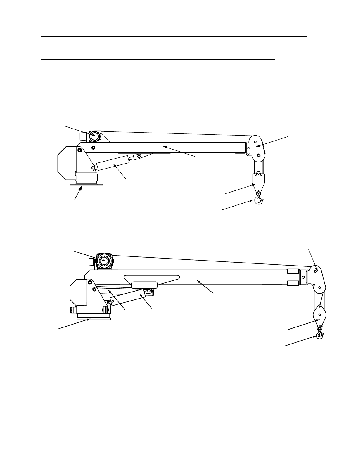
Crane Component Identification
IMT electric-hydraulic cranes are designed to lift a variety of materials. These cranes are
typically mounted on a vehicle chassis, but they can have stationary mounts. Instructions on
how to operate the crane may refer to various crane components. Use the crane layout to help
you identify the appropriate crane components.
SNATCH
BLOCK
HOOK
ASSEMBLY
BASE
LOWER
CYLINDER
WINCH
LOWER
BOOM
EXTENSION
BOOM
Model 6006i has a power arm to help lift larger loads.
SNATCH
BLOCK
HOOK
ASSEMBLY
BASE
LOWER
CYLINDER
WINCH
LOWER
BOOM
EXTENSION
BOOM
POWER
ARM

Chapter 2 Operation 9
General
To operate this crane, you must conform to physical and behavioral requirements and must have
certain abilities as defined by ANSI B30.22 chapter 22-3 and the Occupational Safety and Health
Administration (OSHA). There may be additional operator requirements defined by local, state
or federal regulations in your area. Make sure you are following all regulations regarding crane
operation.
Prior to beginning work at a job site, you should understand:
Crane Safety
Crane Controls
Crane Load Limits
Operating Procedures
You should have the chance to practice operating the crane prior to using the crane in a job site
application.
The operator must understand what to do in case of emergency, and be prepared to take
emergency action at any time. Safe operation is the responsibility of the operator, maintenance
and inspection personnel. Safety has been a major consideration in the design and manufacture
of this equipment, but only the operator and maintenance personnel can insure a safe work
environment.
Daily Safety Inspection
Using the Crane Log, IMT Manual No. 99900686, or the inspection checklist in the reference
section of this manual, inspect the crane on a daily, weekly, and monthly basis. Use the
following list as a guide when you are inspecting your unit at start-up and during operation:
1 Vehicle - Check oil level, battery, lights, brakes, and tires for inflation, pressure, cuts, and
loose or missing wheel lugs.
2 Safety Accessories - Check for proper function, oil levels, leaks and malfunctions.
3 Hydraulic Oil Reservoir - Check for proper oil level, leaks and blockages.
4 Weldments - Check visually for damage, especially cracks or breaks in welds.
5 Cylinders - Check for leakage and scored rods.
6 Fasteners - Check pins, sheaves, nuts and bolts for breakage, excessive wear and
tightness.
7 Crane Hooks - Check for the presence of a safety catch, twists, cracks, or damage.

10 IMT Electric-Hydraulic Crane Operation & Safety Manual # 99903618
8 Covers and Guards - Check for missing or improperly maintained covers and guards.
9 Remote Control - Check engine stop switch for function and corrosion.
10 Operation Placards and Safety Decals - Check for illegible or missing decals and placards.
Refer to the decal section of this manual for more information on the required decals.
Replace or repair any items as needed prior to equipment operation.
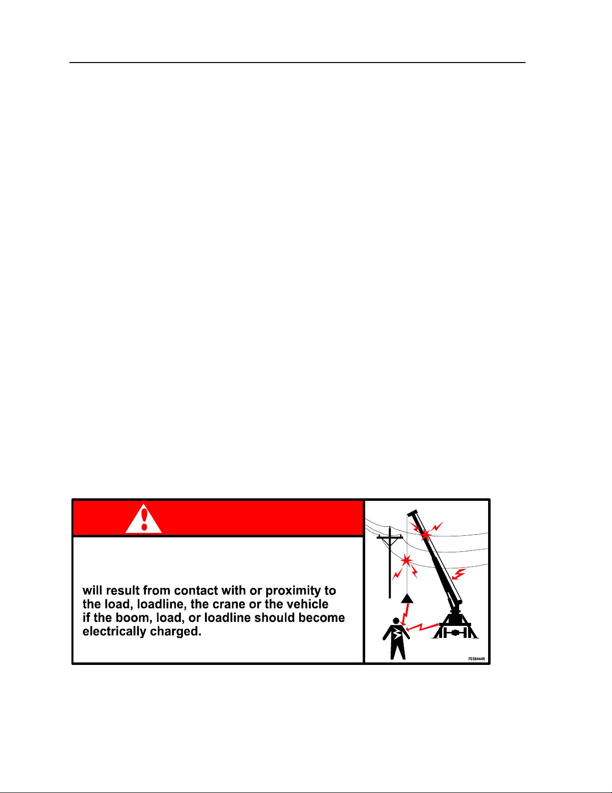
Electrical Hazards
Always operate the crane so that no part of the crane or load enters the "Danger Zone", the
minimum clearance distance for a powerline.
NOTE
THE DANGER ZONE OF A PARTICULAR POWERLINE IS BASED UPON ITS VOLTAGE.
HIGH VOLTAGE LEVELS INCREASE THE DANGER ZONE. SEE FIGURE.
DANGER ZONE
AVOID THIS AREA.
DANGER ZONE FOR CRANES
OPERATING NEAR ELECTRICAL
POWERLINES
REQUIRED CLEARANCE OF CRANES FROM ELECTRICAL TRANSMISSION LINES
NORMAL VOLTAGE
kV (Phase to Phase)
MINIMUM CLEARANCE
REQUIRED Feet (meters)
From 0 to 50 10 (3.05)
From 50 to 200 15 (4.60)
From 200 to 350 20 (6.10)
From 350 to 500 25 (7.62)
From 500 to 750 35 (10.67)
OPERATION NEAR HIGH
VOLTAGE POWERLINES
From 750 to 1000 45 (13.72)
From 0 to 0.75 4 (0.22)
From 0.75 to 50 6 (0.83)
From 50 to 345 10 (3.05)
From 345 to 750 16 (4.87)
OPERATION IN TRANSIT WITH
NO LOAD AND BOOM OR MAST
LOWERED
From 750 to 1000 20 (8.10)
Chapter 2 Operation 11
For maximum safety during work near powerlines, adhere to the following guidelines:
During windy conditions, allow additional clearance.
Do not rely on cage-type boom guards, insulating links, or proximity warning devices for
safety. Adhere to the required distances listed in table titled REQUIRED CLEARANCE OF
CRANES FROM ELECTRICAL TRANSMISSION LINES.
Contact the utility company before beginning work near powerlines.
Always assume overhead lines to be energized.
Avoid transporting a crane over uneven terrain.
When using rope to steady a load or restrain spinning of the load, be aware that rope will
also conduct electricity, especially if wet or damp.
Reduce operating speed when in close proximity to powerlines in order to allow the operator
more reaction time.
IF ELECTRICAL CONTACT OCCURS:
1 Shut off all power.
2 Break contact of any person in contact with a live conductor by using rubber hose, dry rope,
or dry wood. DO NOT attempt this unless you are certain that all power is off.
3 Call 911 or the local emergency service.
4 Administer first aid.
5 Avoid the area around the crane, as high voltage travelling through a crane will charge the
ground.
ELECTRICAL CONTACT FOLLOW-UP:
1 Inspect and repair any equipment affected by electrical contact.
2 Replace any wire rope which has had high voltage contact.
DANGER
ELECTROCUTION HAZARD
DEATH OR SERIOUS INJURY
KEEP CLEAR OF TRUCK AND LOAD

12 IMT Electric-Hydraulic Crane Operation & Safety Manual # 99903618
Crane Capacity
The IMT crane is designed to lift specific loads. These loads are defined on the capacity placard
mounted near the operator’s station and on the crane. Exceeding the limits presented on the
capacity placard will create severe safety hazards and will shorten the life of the crane. The
operator and other concerned personnel must know the load capacity of the crane and the
weight of the load being lifted!
WARNING
NEVER EXCEED THE CRANE’S RATED LOAD CAPACITIES. DOING SO WILL CAUSE
STRUCTURAL DAMAGE AND DAMAGE TO WINCHES AND CABLES WHICH CAN LEAD
TO DEATH OR SERIOUS INJURY.
NOTE
LOAD LIMIT INFORMATION ON THE CAPACITY PLACARD IS FORMULATED ON 85% OF
TIPPING. TIPPING REFERS TO THE CRANE ACTUALLY TIPPING WITH ITS OPPOSITE
OUTRIGGER AND TIRES HAVING BROKEN CONTACT WITH THE SURFACE.
Prior to lifting a load:
1 Determine the weight of the load.
2 Determine the weight of any load handling devices.
3 Add the weight of the load and the weight of the load handling devices. The sum is the total
weight of the load being lifted.
4 Determine the distance from the centerline of crane rotation to the centerline of the load
being lifted.
5 Determine the distance from the centerline of crane rotation to the centerline of where the
load is to be moved to.
6 The actual distance used should be figured as the larger of items 4 and 5 above.

Chapter 2 Operation 13
Load Ratings
The maximum load chart is a representation of the MAXIMUM loads for which your crane is
rated. The Overload Protection System prevents loads significantly over these ratings. The
actual load rating for your installation will be determined by other factors. Remember that just
because the load chart says a given load is possible, that load may not be possible under some
configurations without tipping the truck. Conduct a load stability test in accordance with Crane
Load–Stability Test Code, Society of Automotive Engineers (SAE) J765, to determine the actual
loading capacities for a given installation. Contact the factory for more information.
All crane functions are hydraulic except the hoist, which is electric. The hydraulic functions can
be actuated simultaneously, but when the crane is loaded it is best to actuate one function at a
time. Simultaneous actuation of two or more functions will momentarily result in a lower than
rated load capacity.
14 IMT Electric-Hydraulic Crane Operation & Safety Manual # 99903618
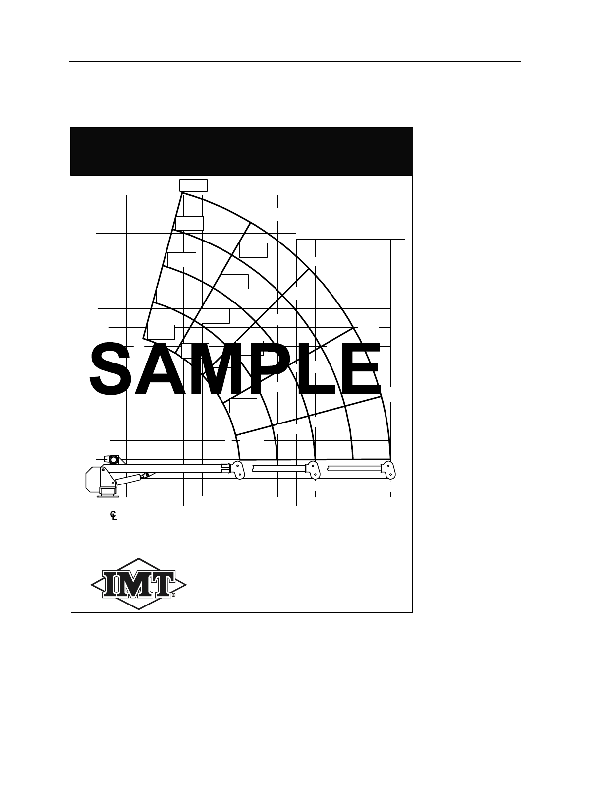
Capacity Chart
IOWA MOLD TOOLING CO., INC.
BOX 189, GARNER, IA 50438-0189
TEL: 641-923-3711 FAX: 641-923-2424
70396783
3203i CAPACITY CHART
10'
12'
14'
16'
2' 4' 6' 8' 10' 12' 14'0
75°
60°
45°
30°
15°
2'
4'
8'
0
(Base)
6'
725
836
990
1212
1567
1721
1346
1100
933
807
982
1141
1342
1640
2100
2916
2302
1888
1600
1400
3088
3200
3200
3200
DISTANCE IN FEET / LOAD IN POUNDS.
Weight of load handling devices are part of the load lifted
and must be deducted from the capacity.
Maximum 1-part line
capacity is 1600 lbs.
For greater loads, use
2-part line.
NOTE: Boxes denote
2-part line.
1500 954 700
2625

Chapter 2 Operation 15
Outriggers
An outrigger (part # 32000513) or stiffening leg is recommended for stabilizing the truck. It
should be deployed before lifting any load. The outrigger extends three feet out to the side of
the truck on the crane side, and has the ability to level the truck bed before lifting. Always level
the truck bed to within 1% grade before lifting the load. Refer to SAEJ765 “Crane Load–Stability
Test Code” procedures for determining crane load stability.
CAUTION
AVOID EQUIPMENT DAMAGE! NEVER LIFT A LOAD WITHOUT DEPLOYING
OUTRIGGERS.
Prior to beginning a lift, fully deploy outriggers and lock them into position. If blocking is
necessary, it should be strong enough to prevent crushing and of sufficient area and thickness to
completely support the stabilizer pad.
Initial Operation
Before operating your crane for the first time, check the hydraulic oil level. The proper oil level is
1 to 1–1/2” below the top of the fill hole. Install the breather cap which is supplied with your
crane. Before lifting a load, check the crane for proper function. If a problem is found, refer to
the troubleshooting section in this manual. Rotate the crane a full circle and back to check for
proper clearance.
Crane Operation
Size of Load
1 Do not load the crane beyond the specifications of the load rating chart, except for test
purposes.
2 Be sure the load to be lifted is within the rated capacity of the crane in its existing
configuration.
3 When loads that are not accurately known are to be lifted, make sure the weight of the load
does not exceed the crane rating at the maximum radius at which the load is to be handled.
Operational Aids
1 The use of operational aids such as overload prevention or two–block prevention does not
replace the need to comply with size of load requirements.

16 IMT Electric-Hydraulic Crane Operation & Safety Manual # 99903618
2 If operational aids are inoperative or malfunctioning, do not use the crane to lift any loads.
Warning Sign
If there is a warning sign on the crane controls, do not operate the crane until the warning sign
has been removed by an appointed person.
Attaching the Load
1 Do not wrap the hoist rope around the load.
2 Attach the load to the hook using slings or other devices of sufficient capacity.
Holding the Load
1 Test crane controls at the start of a new shift. If any controls fail to operate properly, they
must be adjusted or repaired before operations are begun.
2 Do not leave the controls while the load is suspended.
3 Do not allow anyone to stand or pass under a suspended load.
Moving the Load
1 Make sure:
a) The crane is level and blocked, where necessary.
b) The load is well secured and balanced in the sling or lifting device before it is lifted more
than a few inches.
c) The lift and swing path is clear of obstructions.
2 Before starting the lift, make sure:
a) The hoist rope is not kinked.
b) Multiple–part lines are not twisted around each other.
c) The hook is secured to the load in such a manner as to minimize swinging.
d) In case of a slack rope condition, the rope must be seated on the drum and in the
sheaves as the slack is removed.
e) The effect of ambient wind on the load and on crane stability is taken into consideration.
3 During the lifting operations, make sure:
a) There is no sudden acceleration or deceleration of the moving load.
b) The load, boom or other parts of the machine do not contact any obstruction.
4 Limit boom side loading to freely suspended loads. The crane must not be used for dragging
loads sideways.
5 Do not move loads over people.
6 Keep more than five full wraps of rope on the winch drum.
7 While in transit, take the following additional precautions:
a) Position the crane boom in line with the direction of motion of the truck.

Chapter 2 Operation 17
b) Lash or restrain the empty hook so that it cannot swing freely.
c) Do not leave loads suspended from the hook.
8 When rotating the crane, avoid sudden starts and stops. When reversing rotation direction,
pause to allow load swing to subside before rotating in the opposite direction.
9 Do not use this crane for transporting or lifting personnel.
Power Failure
If power fails during operations:
1 Move all controls to the off or neutral position.
2 Land the suspended load, if practical.
Post Operation
Before leaving the crane unattended:
1 Land any load, bucket, lifting magnet or other device.
2 Put controls in the off or neutral position.
3 Disconnect and stow the control pendant.
The operator must be familiar with the equipment and its proper care. If adjustments or repairs
are necessary, the operator shall promptly report this to the appointed person and shall also
notify the next operator.
Overload Protection System
The crane is equipped with a system that, when activated by excess moment load, locks out the
hoist up, boom extend, and boom down functions. An overload condition is sensed as excess
pressure in the boom up hydraulic cylinder.
CAUTION
DO NOT HOIST OR EXTEND A LOAD WITH THE BOOM IN THE FULL DOWN POSITION.
To make sure that the overload protection system works properly, always raise the boom up off
the bottom of the cylinder before hoisting or extending the load. Failure to do this may result in a
crane overload condition with serious consequences. When the crane goes into overload mode,
the operator should relieve the overload by lowering the hoist or retracting the boom. The best
system for preventing overload is a well-trained, cautious crane operator. The overload
protection system should not be viewed as a substitute for sensible safety precautions, but
rather a backup system in case of operator error. Remember, when the overload system is
triggered, the crane is OVERLOADED. The pressure setting of the overload protection system
is factory set and should not be tampered with. If the operator is in doubt as to whether the
overload protection system is working properly, he should contact his supervisor immediately.

18 IMT Electric-Hydraulic Crane Operation & Safety Manual # 99903618
Anti-Two-Block System
If your crane is equipped with power extension, it has a switch which stops the boom extension,
hoist up and boom down functions. This switch is connected to a hanging weight at the crown
block of the boom. It is activated before the traveling block can come in contact with the boom
crown. This system is designed to be failsafe in that if any of the components should fail or
become disconnected, the target functions will not work until it is replaced, repaired or
reconnected. If the operator is in doubt as to whether the anti-two-block system is working
properly, he should contact his supervisor immediately.
Operation in Adverse Conditions
Operating your crane in adverse weather conditions can affect the crane performance. Please
note the following operation procedures for adverse weather conditions.
1 Dusty and Sandy Areas - Operating in dusty or sandy areas presents special problems due
to the abrasive action of dust which shortens the life of parts. Make every effort to keep dust
and sand out of the moving parts of the crane machinery and engine. Keep lubricants clean,
and lubrication and fluid fill areas capped tightly.
2 High Humidity and Salt Air - Moisture and salt will cause deterioration of paint, cables, wiring
and all exposed metallic parts. Keep parts dry and well lubricated in high humidity or salt air
conditions. Keep parts thoroughly lubricated, and remove rust and corrosion if and when it
appears.
3 High Altitudes - Operation at high altitudes presents special problems due to lower
atmospheric pressure and wide temperature ranges. Consult the vehicle owner’s manual
regarding operating the vehicle at high altitudes.
Cold Weather
For cold weather operation with temperatures of -25º F or lower, the following procedures must
be followed:
1 Start the truck and run at manufacturer’s recommended idle speed for proper warm up.
2 After approximately 45 minutes of truck warm up time, engage the PTO.
3 With the PTO fully engaged and the truck engine running at idle speed, let the hydraulic
system oil circulate.
Other manuals for 3203i
1
This manual suits for next models
2
Table of contents
Other IMT Construction Equipment manuals


Popular Construction Equipment manuals by other brands


National Crane
National Crane 600H Service manual

MULTIQUIP
MULTIQUIP Whiteman WM120PH Series Operation and parts manual

Husqvarna
Husqvarna Soff-Cut 4000 Operator's manual

Toro
Toro Line Painter 1200 Operator's manual

Dawson
Dawson EMV-70 METRIC Operator's instructions/Spare parts list

Fayat Group
Fayat Group Dynapac CA25 instruction manual


