www.petsafe.net 5
Setting up the Wire Break
Locator Transmitter
1. TurntheexistingcontainmentTransmitteroff.Disconnect
theBoundaryWiresfromtheTransmitterandunplugthe
ACpoweradapterfromtheTransmitter.
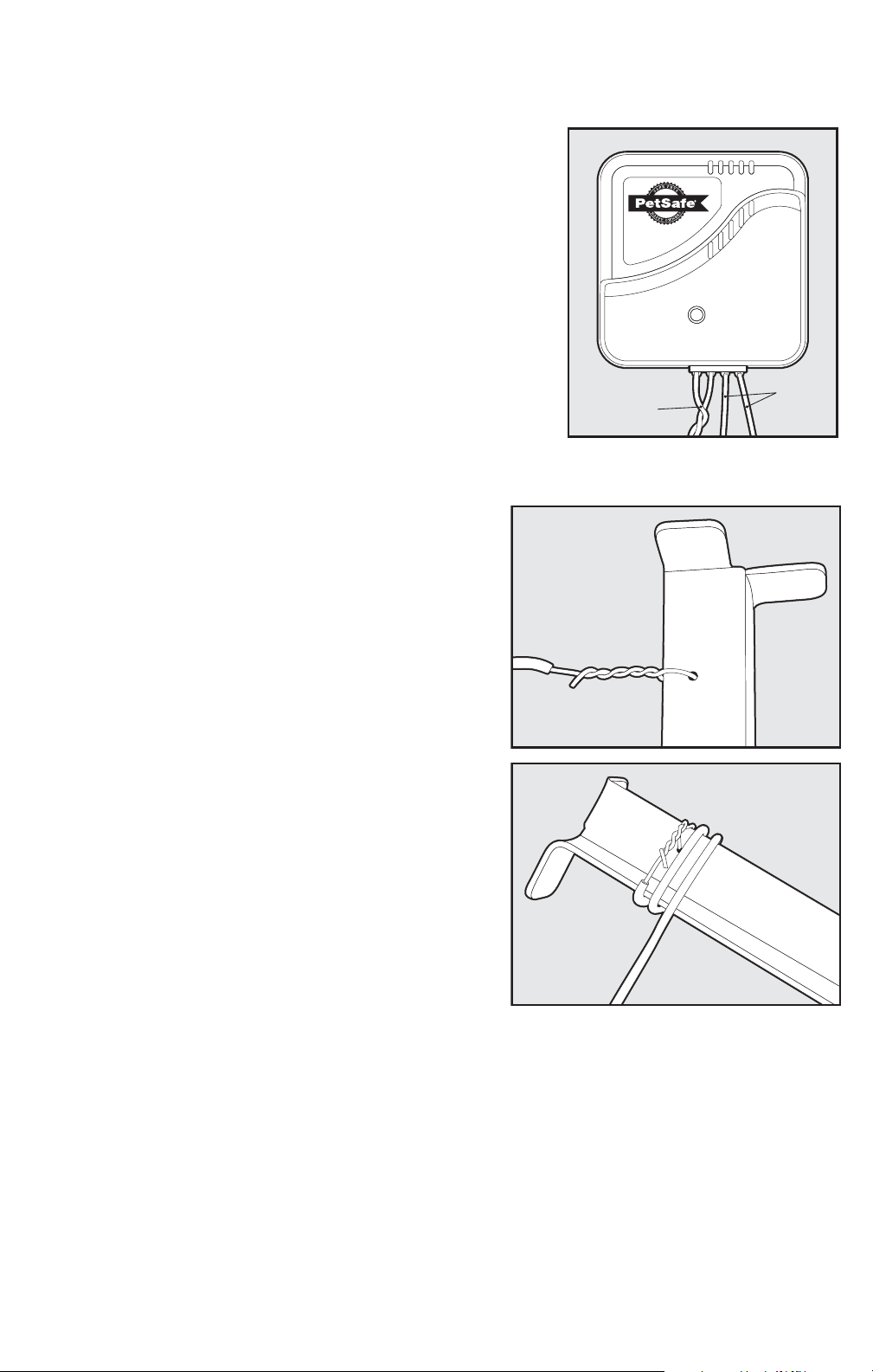
2. Connectthe2BoundaryWirestothetwoREDLOOPwire
connectorsontheWireBreakLocatorTransmitter
3. ForproperoperationoftheTransmitter,twoseparate
groundingwiresmustbeconnectedtotheBLACK
GROUNDterminalsoftheWireBreakLocatorTransmitter.
Usingthespoolofwiresuppliedinthekit,Strip3/8”of
insulationoffofthewireononeendofthespool.Insert
thestrippedendofthespoolintooneoftheGROUND
terminalsontheWireBreakLocatorTransmitterasshown
inFigure 1.
NOTE: Each ground connection on the Transmitter must be
connected to a separate grounding stake supplied in the
Boundary
Wires
Ground
Wires
1
RFA-450 kit. These grounding stakes must be inserted into the earth outside of the home/garage
for the transmitted signal to operate properly. These stakes should be 2-3 feet apart.
4. Slipthesmallwirespoolthoughyourngerand
unrollthewirebyallowingthespooltorotateonyour
ngerasyouwalkawayfromtheWireBreakLocator
Transmitter.Walktoanoutsideareawherethere
isasmallsectionofgroundavailabletoinsertthe
groundingstakes.Note:Itisrecommendedtokeep
thesegroundconnectionwiresasshortaspossibleby
trimmingoffanyexcesswirebetweentheWireBreak
LocatorTransmitterandtheintendedlocationofthe
groundingstakes.Cutthewireandstrip2inchesof
insulationoffofthewiretoconnecttothegrounding
stake.Placethewirethroughthesmallholeinthe
groundingstakeandtightlytwistthewireasshownin
Figure 2.Makesurethatthewireistightlywrapped
aroundthestakeandthatthecopperismakinggood
connectionwiththemetalonthegroundingstakeas
showninFigure 3.RepeatSteps3and4toconnect
theotherwiretothesecondTransmitterground
terminalandgroundingstake.
5. Thegroundingstakesshouldbelocatedatleast2-3
feetapartintheground.Insertthegroundingstakes
intothegroundabout8incheswithabout
2inchesremainingfromtheend.Afterthegrounding
stakesareinstalled,makesurethatthewireistightly
wrappedaroundthestakeandthatthecopperis
makinggoodconnectionwiththemetalonthe
groundingstakeasshowninFigure 3.
2
3
6. RechecktheLOOPandGROUNDwireconnectionsattheWireBreakLocationTransmitterand
verifythattheyaresecurelyinstalled.
7. TheWireBreakTransmitterispoweredusingaRadioSystems®Corporationadapterpart
numberRFA 372, 650-229, 300-006, or Innotek®adapter part number 0400036-1(notsuppliedinthe
RFA-450system).ConnectpowertotheWireBreakLocationTransmitterusingtheadapter
fromyourIn-Groundcontainmentsystem.NOTICE: Do not use Radio Systems®Corporation
adapter part number 650-230 or Innotek®adapter part number 0400042-1. Damage to the
Wire Break Locator Transmitter will occur. Check the adapter before plugging into the Wire
Break Locator Transmitter and verify that the output is specified at 12VAC.
8. PlugthePowerAdapterintothePowerJackandACPowerOutlet.ThegreenPowerLightwill
ashquicklyindicatingpowerissupplied.