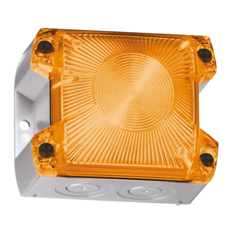
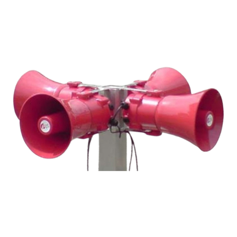
Pfannenberg PA 1 User manual

Betriebsanleitung PA 1 / PA X 1-05
06/2020 Seite 1 / 10 086200000b
de
en
fr
it
ru
Schutzvermerk nach DIN ISO 16016 beachten!
Originalsprache
Inhalt
1. Bestimmungsgemäße Verwendung..............................................................................................................1
2. Lieferumfang....................................................................................................................................................1
3. Abmessungen..................................................................................................................................................2
4. Technische Daten ...........................................................................................................................................2
4.1 Allgemein...............................................................................................................................................2
4.2 Elektrische Kenndaten AC.....................................................................................................................3
4.3 Elektrische Kenndaten DC.....................................................................................................................3
5. Zulassungen....................................................................................................................................................4
6. Inbetriebnahme................................................................................................................................................5
6.1 Sicherheitshinweise...............................................................................................................................5
6.2 Elektrischer Anschluss PA 1........................................................................................................................6
6.3 Elektrischer Anschluss PA X 1-05.........................................................................................................6
7. Toneinstellungen (auf der Treiberplatine im Oberteil)................................................................................6
7.1 Änderung der Töne durch externe Ansteuerung...................................................................................7
7.1.1 Tonstufenauswahl durch Steuereingang (TAS), DC- und AC-Versionen.........................................7
7.1.2 Tonstufenauswahl durch Versorgung über Steuereingang (TAV) – alle DC-Versionen...................8
7.1.3 Tonstufenauswahl durch Verpolung (TAR) – alle DC-Versionen (außer Option –SSM)..................9
8. Option...............................................................................................................................................................9
9. Zubehör..........................................................................................................................................................10
10. Wartung, Service, Instandhaltung.............................................................................................................10
11. Außerbetriebnahme, Demontage und Entsorgung..................................................................................10
Anhang Tonartentabelle und Ansteuerung der Töne
1. Bestimmungsgemäße Verwendung
Schallgeber der PA- Serie sind für die Signalisierung von z.B. Gefahrzuständen in Industrie, Gewerbe und
Gebäudebereichen bestimmt. Bei Nutzung der Schallgeber-Blitzleuchten-Kombination (PA X 1-05) besteht
zusätzlich die Möglichkeit der optischen Signalisierung.
Die Schallgeber erzeugen akustische Signale in 80 verschiedenen Tonarten, die mit Hilfe eines internen
Schalters ausgewählt werden können. Es besteht die Möglichkeit, durch externe Ansteuerung auf maximal 3
weitere Töne umzuschalten.
Die Geräte nur in unbeschädigtem Zustand innerhalb der spezifizierten Kenndaten betreiben. Die Funktion des
Gerätes ist nur gewährleistet, wenn Ober- und Unterteil korrekt zusammengefügt ist.
Die Geräte sind für den Einsatz im Innen- und Außenbereich geeignet und nur für die ortsfeste Montage be-
stimmt.
2. Lieferumfang
Der Lieferumfang besteht aus:
1x Signalgerät
1x Membrannippel M20
1x Kurzanleitung
1x Widerstand (nur bei –SSM-Versionen)

Betriebsanleitung PA 1 / PA X 1-05
06/2020 Seite 2 / 10 086200000b
de
3. Abmessungen
PA 1
PA X 1-05
M20-Ausbruch vorbereitet
M20-Ausbruch vorbereitet
M20-Ausbruch vorbereitet
Bohrbild im Inneren des Gehäuses (PA 1)
Bohrbild im Inneren des Gehäuses (PA X 1-05)
M20-Ausbruch vorbereitet
M20-Ausbruch vorbereitet
4. Technische Daten
4.1 Allgemein
PA 1 PA X 1-05
Max. Schallpegel 105 dB (A) 1m
Lautstärkeregelung max. -12dB
Töne 80
Blitzenergie - 5 J
Blitzfrequenz - 1 Hz
Einschaltdauer 100%
Anschlussklemmen 0,14 - 2,5mm² feindrähtig / AWG24 - AWG 14
Schutzart IP 66 (EN 60529), Type 4 & 4x
Schlagfestigkeit IK08 (EN 50102)
Schutzklasse II

Betriebsanleitung PA 1 / PA X 1-05
06/2020 Seite 3 / 10 086200000b
de
Betriebstemperatur -40 °C…+55 °C
Lagertemperatur -40 °C…+70 °C
Max. rel. Luftfeuchte 90%
Kabeleinführung 4x M20 vorgeprägt 5x M20 vorgeprägt
Dichtbereich der
Durchführungstülle
7 – 13 mm Bei Verwendung von Kabeldurchmessern < 7 mm eine Kabelver-
schraubung mit ausreichender Schutzart vorsehen
Gehäusematerial PC/ ABS Blend
Haubenmaterial PC
Einbaulage beliebig
Haubenfarben klar, weiß, gelb, orange, rot, grün, blau
4.2 Elektrische Kenndaten AC
PA 1 PA X 1-05
Bemessungsspannung
(Begrenzungen siehe Zu-
lassungen)
24 V
50/60 Hz 48 V
50/60 Hz 115 V
50/60 Hz 230 V
50/60 Hz 24 V
50/60 Hz 115 V
50/60 Hz 230 V
50/60 Hz
Spannungsbereich 18 – 30 V
44 – 52 V
95 –
127 V
195 –253 V
18 –
30V
95 – 127V
195 –
253V
Stromaufnahme Schall-
geber (max)
150 mA 150 mA 30 mA 16 mA 150 mA 30 mA 16 mA
Stromaufnahme Blitz-
leuchte (max)
- - - - 800 mA 120 mA 90 mA
Leistungsaufnahme 4,5 VA 9 VA 4,5 VA 4,5 VA 34,5 VA 18,5 VA 25 VA
4.3 Elektrische Kenndaten DC
PA 1 PA X 1-05
Bemessungsspannung
(Begrenzungen siehe Zulassungen)
24 V oder
12 – 48 V
120 V 12 V 24 V 48 V
Spannungsbereich 10 – 57 V 108 – 132 V 10 – 15 V 18 – 30 V 40 – 57 V
Stromaufnahme Schallgeber (max) 80 mA 30 mA 25 mA 70 mA 80 mA
Stromaufnahme Blitzleuchte (max) - - 700 mA 360 mA 170 mA
Leistungsaufnahme
12 – 48 V: 4 W
24 V: 2 W 3,6 W 8 W 11,5 W 11,5 W

Betriebsanleitung PA 1 / PA X 1-05
06/2020 Seite 4 / 10 086200000b
de
5. Zulassungen
(Zulassungen gelten für gekennzeichnete Geräte)
Bauproduktver-
ordnung
(305/2011/EU)
12
PA 1: 0786-CPD-21182 PA X 1-05: 0786-CPD-21220
PA 1 PA X 1-05
Optionen –SSM (24V DC)
Bemessungsspannung 24 – 48 V DC 24V DC 48V DC
Spannungsbereich ge-
mäß EN54-3, EN54-23
18 V – 57 V
Option: -SSM (18 V – 30 V)
18 - 30V 40 - 57V
Haubenfarbe Blitzleuchte - rot, klar
Ton
2
15
60
104
131
146
konform zur Bauproduktenrichtlinie (89/106/EWG)
1200Hz-500Hz (Sägezahn/ Saw tooth) DIN/PFEER P.T.A.P.
500Hz-1200Hz (Ansteigender Ton/ Slow whoop)
825Hz (Dauerton/ Continuous)
660Hz (Unterbrochener Ton/ Intermittent)
800Hz/ 1000Hz (Wechselton/ Alternating)
544Hz/ 440Hz (NF S 32-001)
Signalisierungsbereich
EN54-3:
siehe Dokument 30303-005-1
EN 54-23 Kategorie O:
siehe Dokument 30303-005-1
Umweltschutzklasse Typ B
Einbaulage beliebig siehe Dokument 30303-005-1
Die Prüfung erfolgte unter Verwendung des mitgelieferten Membrannippels und der äuße-
ren Befestigungsbohrungen.
VdS PA 1 PA X 1-05
G 212115
G 212188
Daten siehe Bauproduktverordnung (305/2011/EU)
GL
61062-13 HH
Umweltkategorie C, H, EMC1
MED MEDB00002BH
CNBOP 2015/2014 2017/2014
UL, cUL
S7256
UCST, UCST7, ULSZ, ULSZ7, UEES, UEES7 (weiterführende Informationen siehe Seite 4
bis 5 im englischsprachigen Kapitel)
Keine Zulassungen für PA1, 48V AC.

Betriebsanleitung PA 1 / PA X 1-05
06/2020 Seite 5 / 10 086200000b
de
6. Inbetriebnahme
6.1 Sicherheitshinweise
GEFAHR- Lebensgefahr durch Stromschlag
Spannungsführende Geräte und freiliegende Anschlussleitungen können Stromschläge erzeugen
und schwere Unfälle verursachen.
Arbeiten an elektrischen Anschlüssen dürfen nur elektrotechnisch geschulte und autorisierte
Fachkräfte durchführen.
Vor der Montage alle Zuleitungen spannungsfrei schalten und gegen Wiedereinschalten si-
chern. Spannungsfreiheit immer sicherstellen.
Entladungsphase von 5 Minuten für die elektrischen Komponenten abwarten. Erst danach
Gerät öffnen.
Das Anlegen der Betriebsspannung darf nur bei fest verschlossenem Gehäuse erfolgen.
WARNUNG - Gefahr durch unzulässigen Einsatz der Geräte
Der nicht bestimmungsgemäße Einsatz kann zu schweren Unfällen führen.
Bei der Installation darauf achten, dass die Anschlussleitung gegen Zug und Verdrehen ab-
gesichert ist.
Die Geräte sind nur für die ortsfeste Montage bestimmt.
Zur Gewährleistung der dauerhaften Funktion:
in staubreicher Umgebung oder im Außenbereich den Schalltrichter nicht nach oben gerichtet
montieren.
GEFAHR - Gefahr durch Beschädigung der Geräte
Nichtbeachtung der Typenschild-Angaben kann zu schweren Unfällen führen.
Bei Installation und Wartung der Geräte immer die Angaben auf dem Typenschild beachten.
VORSICHT - Verletzungsgefahr durch scharfe Kanten oder erhitzte Bauteile
Bei Installations-, Montage-, oder Service-/ Wartungsarbeiten Handschuhe tragen.
Verdrahtung entfernt von scharfen Kanten, Ecken und internen Komponenten vornehmen.
VORSICHT - Beeinträchtigung des Hörvermögens
Um eine Beeinträchtigung des Hörvermögens zu verhindern, bei Arbeiten/ Tests eine Schall-
schutzausrüstung tragen.
VORSICHT – Beeinträchtigung des Sehvermögens
Bei Verwendung der Schallgeber-Blitzleuchten-Kombination:
Um eine Beeinträchtigung des Sehvermögens zu verhindern, den dauernden, direkten Blick
in die aktivierte Leuchte vermeiden.
Öffnen des Gehäuses
Verschließen des Gehäuses
Durch Lösen der vier
Deckelschrauben lässt
sich das Oberteil ab-
nehmen
Verschließen des Ge-
häuses durch Drehen
der Deckelschrauben
in die Endstellung bis
zur Verrastung.
Das Gerät wird in nicht verschlossenem Zustand ausgeliefert.
Plombierstopfen für die Gehäuseschrauben sind als Zubehör erhältlich.
Kabeldurchführungen
Der mitgelieferte Membrannippel kann durch eine Kabelverschraubung oder durch einen M12-Steckverbinder
mit einem Flanschmaß von M20 ersetzt werden.
Nur Kabelverschraubungen mit einer Schutzart von mindestens IP66 an den entsprechenden Durchbrü-
chen montieren.
Bei Kabeldurchmessern von <7 mm eine Kabelverschraubung mit ausreichender Schutzart verwenden.
IP 66 nur bei nach außen ge-
richtetem Trichter der
Membrane.
Nach Montage des Kabels
Reste der Membrane entfernen.
Membrannippel IP 66
(mitgeliefert)
Kabelverschraubung
IP 66 (Option)
M12- Steckverbinder IP 66,
für Kleinspannungs-Geräte
(Option)
3/8
1. 2.
3/8
1. 2.

Betriebsanleitung PA 1 / PA X 1-05
06/2020 Seite 6 / 10 086200000b
de
6.2 Elektrischer Anschluss PA 1
Platine im Unterteil:
Betriebsspannungsanschluss
6.3 Elektrischer Anschluss PA X 1-05
Gemeinsamer Anschluss von Blitzleuchte
und Schallgeber (Werkseinstellung)
Getrennter Anschluss von Blitzleuchte
und Schallgeber
Stecker von der Blitz-
leuchtenplatine
Stecker von der
Blitzleuchten
-
platine
Betriebsspannungsan
schluss
Betriebsspannungs-
anschluss Schallgeber
Betriebsspannungs-
anschluss Blitzleuchte
7. Toneinstellungen (auf der Treiberplatine im Oberteil)
Der gewünschte Ton wird mit dem Tonartenschalter S3 (auf der Treiberplatine im Oberteil) ausgewählt. Die
möglichen Töne sind in der Tonartentabelle im Anhang beschrieben.
Nach Anlegen der Versorgungsspannung wird der Ton erzeugt.
DC-Version und 48 AC AC- Version
Lautstärkeregler
Hinweis:
Um EN54-3 konform zu sein,
muss sich der Lautstärkeregler in
der Maximal-Position befinden.
Tonartenschalter
S3
Diode nicht überbrückt
Polarität negativ
Werkseinstellung
Diode nicht überbrückt
Polarität positiv
Diode überbrückt
Polarität negativ
Diode überbrückt
Polarität positiv
S1B (nur DC)
Auswahl der Polarität
der Steuerspannung für
C1 und C2
S1A (nur DC)
Überbrückung der
Verpolungsdiode
S1A
S1B
S3
S3
S1B/ S1A nur bei
DC-Versionen

Betriebsanleitung PA 1 / PA X 1-05
06/2020 Seite 7 / 10 086200000b
de
7.1 Änderung der Töne durch externe Ansteuerung
Für Anwendungen, die zusätzlich zum Grundton weitere Töne benötigen, besteht die Möglichkeit, bis zu drei
weiteren Tonarten mithilfe der folgenden elektrischen Ansteuerungen zu erreichen.
Grundsätzlich wird erst der gewünschte Grundton (♪, siehe Tonartentabelle im Anhang) mit dem Tonarten-
schalter S3 auf der Treiberplatine eingestellt. Die korrespondierenden zusätzlichen Töne (C1, C2, C1+C2) sind
der Tabelle „Ansteuerung der Töne“ im Anhang zu entnehmen.
7.1.1 Tonstufenauswahl durch Steuereingang (TAS), DC- und AC-Versionen
DC-Version:
Hinweis: Versorgungsspannung immer zusammen mit den Steuereingängen angelegen.
Achtung: Ist die Steuerspannung größer als die Versorgungsspannung oder die Versorgungsspannung liegt
nicht an, erfolgt die Betriebsstromversorgung über die Steuereingänge. Eine entsprechende Belastbarkeit
muss dann gewährleistet sein.
Negative Ansteuerung: (Werkseinstellung)
Schalterstellung wie folgt vornehmen:
S1A auf (Diode nicht überbrückt)
Umschalter S1B auf „–“
(auf der Treiberplatine)
Ton C2
Ton C1
Betriebsspannung
Positive Ansteuerung:
Schalterstellung wie folgt vornehmen:
S1A auf (Diode nicht überbrückt)
Umschalter S1B auf „+“ (positive
Ansteuerung)
(auf der Treiberplatine)
Ton C2
Ton C1
Betriebsspannung
Ton C1
Ton C2
Ton C1
Ton C2

Betriebsanleitung PA 1 / PA X 1-05
06/2020 Seite 8 / 10 086200000b
de
AC-Version:
Hinweis: Versorgungsspannung immer zusammen mit den Steuereingängen angelegen.
24 V AC/ 115/ 230 V AC: Phase „L“ der Versorgungsspannung an die Steuereingänge C1 bzw. C2 anlegen.
Nur 48 V AC: „N“ der Versorgungsspannung an die Steuereingänge C1 bzw. C2 anlegen.
Ton C2
Ton C1
Betriebsspannung
7.1.2 Tonstufenauswahl durch Versorgung über Steuereingang (TAV) – alle DC-Versionen
Hinweis: Nur bei DC-Version anwenden!
Der Schallgeber kann über die Steuereingänge C1 bzw. C2 auf der Anschlussplatine mit Betriebsspannung
versorgt werden. Versorgung und Tonstufenauswahl erfolgt somit gleichzeitig.
Schalterstellung wie folgt vornehmen:
S1A auf (Diode nicht überbrückt)
Umschalter S1B auf „+“
(auf der Treiberplatine)
Minuspol auf der Anschlussplatine anschließen.
Pluspol auf der Anschlussplatine anschließen. Der Grundton (♪) wird erzeugt.
Anschluss der positiven Spannung an C1 auf der Anschlussplatine erzeugt Ton C1.
Anschluss der positiven Spannung an C2 auf der Anschlussplatine erzeugt Ton C2.
Gleichzeitiger Anschluss der positiven Spannung an C1 und C2 auf der Anschlussplatine erzeugt Ton
„C1+C2“.
Grundton
Ton C1
Ton C2
Grundton
Ton C1+C2
Ton C1
Ton C2
Ton C1
Grundton
Ton C2

Betriebsanleitung PA 1 / PA X 1-05
06/2020 Seite 9 / 10 086200000b
de
7.1.3 Tonstufenauswahl durch Verpolung (TAR) – alle DC-Versionen (außer Option –SSM)
Hinweis: Nur bei DC-Version anwenden!
Nicht bei –SSM-Versionen anwenden!
Die Steuereingänge C1 und C2 dürfen auf der Anschlussplatine nicht beschaltet werden!
Schalterstellung wie folgt vornehmen:
S1A auf (Diode überbrückt)
und Umschalter S1B auf „+“
(auf der Treiberplatine)
Durch Verpolung der Betriebsspannung zum Grundton (♪) kann zusätzlich Ton „C1+C2“ gewählt werden:
Grundton
Ton „C1+C2“
8. Option
–SSM (Soft-Start-Modul, nur 24V DC)
Die Einschaltstromspitze wird begrenzt auf:
: max. 2,1 A
: max. 2,1 A
Die Betriebsspannung wird erst ab >7 V zum Betriebsmittel durchgeschaltet.
Betriebsspannungsbereich: 18 V – 30 V DC
Position des Widerstands (1kOhm) wie folgt vornehmen:
Den Widerstand zur Leitungsüberwachung immer im letzten Gerät montieren.
Bei getrenntem Anschluss von Schallgeber und Blitzleuchte Position des zweiten Widerstandes siehe
unten.
Nicht benötigte Widerstände entfernen.
Gemeinsamer Anschluss von Schallgeber und Blitzleuchte:
Getrennter Anschluss von Schallgeber und Blitzleuchte:

Betriebsanleitung PA 1 / PA X 1-05
06/2020 Seite 10 / 10 086200000b
de
9. Zubehör
Artikel-Nr. Bezeichnung
28300000002 Plombierstopfen, 4er-Pack
28912000000 Ersatzverriegelungsbolzen, 4er-Pack
28300000004 Flächendichtung
28300000007 Schalttafeleinbau-Kit PA 1
10. Wartung, Service, Instandhaltung
Bei allen Arbeiten am Gerät Sicherheitshinweise beachten.
Das Gerät erfordert keine besondere Wartung.
Äußere Reinigung mit einer schwachen Seifenlösung ohne Verwendung von Lösungsmittel vornehmen.
Austausch von Komponenten nur mit Originalersatzteilen.
Reparaturen grundsätzlich nur im Herstellerwerk ausführen lassen.
Umbauten, Änderungen, fehlerhafter und unzulässiger Einsatz sowie die Nichtbeachtung der Hinweise dieser
Betriebsanleitung schließen eine Gewährleistung aus.
11. Außerbetriebnahme, Demontage und Entsorgung
Bei allen Arbeiten am Gerät Sicherheitshinweise beachten.
Altgeräte nur von sachkundigen Personen und gemäß geltenden Umweltvorschriften entsorgen.
Altgeräte werden ebenfalls von Pfannenberg fachgerecht entsorgt. Die Anlieferung an eines unserer Her-
stellwerke hat kostenfrei zu erfolgen.

Operating instructions PA 1 / PA X 1-05
06/2020 Page 1 / 11 086200000b
en
Observe proprietary notice in accordance with DIN
ISO 16016!
English translation
Content
1. Intended use....................................................................................................................................................1
2. Scope of delivery ............................................................................................................................................1
3. Dimensions......................................................................................................................................................2
4. Technical data .................................................................................................................................................2
4.1 General..................................................................................................................................................2
4.2 Electrical data AC ..................................................................................................................................3
4.3 Electrical data DC..................................................................................................................................3
5. Approvals.........................................................................................................................................................4
6. Commissioning ...............................................................................................................................................6
6.1 Safety information..................................................................................................................................6
6.2 Electrical connection PA 1.....................................................................................................................7
6.3 Electrical connection PA X 1-05 ............................................................................................................7
7. Tone settings (on the driver board in the upper part).................................................................................7
7.1 Changing the tones by external control.................................................................................................8
7.1.1 Stage selection via control input (TAS), AC and DC versions..........................................................8
7.1.2 Stage selection by supply via control input (TAV) – all DC versions................................................9
7.1.3 Stage selection by reverse polarity (TAR) - all DC versions (except option –SSM).......................10
8. Option.............................................................................................................................................................10
9. Accessories...................................................................................................................................................11
10. Maintenance, service, repairs....................................................................................................................11
11. Decommissioning, dismantling and disposal..........................................................................................11
Annex “Tone type table” and “Control of tones”
1. Intended use
Sounders of the PA series are designed for the signaling of e.g. hazardous conditions in industry, trade and
construction areas. There is also the possibility of visual signaling when the sounder/flashing light combination
(PA X 1-05) is used.
The sounders produce acoustic signals in 80 different tones, which can be selected using an internal switch.
The external control can be used to switch over to a maximum of 3 further tones.
The devices must only be operated when undamaged and within the specified parameters. The function of the
device can only be guaranteed if the upper and lower parts are correctly joined together.
The devices are designed for indoor and outdoor use and are only intended for fixed installation.
2. Scope of delivery
The scope of delivery consists of:
1x Signaling device
1x Diaphragm nipple M20
1x Quick guide
1x Resistor (only for –SSM versions)

Operating instructions PA 1 / PA X 1-05
06/2020 Page 2 / 11 086200000b
en
3. Dimensions
PA 1
PA X 1-05
M20 cutout prepared
M20 cutout prepared
M20 cutout prepared
Drilling pattern inside the housing (PA 1)
Drilling pattern inside the housing (PA X 1-05)
M20 cutout prepared
M20 cutout prepared
4. Technical data
4.1 General
PA 1 PA X 1-05
Max. sound level 105 dB (A) 1m
Volume control max. -12dB
Tones 80
Flash energy - 5 J
Flash frequency - 1 Hz
Duty cycle 100%
Connecting terminals 0.14 - 2.5mm² fine stranded / AWG24 - AWG 14
Ingress protection IP 66 (EN 60529), Type 4 & 4x
Impact strength IK08 (EN 50102)
Protection class
II double insulated equipment

Operating instructions PA 1 / PA X 1-05
06/2020 Page 3 / 11 086200000b
en
Operating temperature -40 °C…+55 °C
Storage temperature -40 °C…+70 °C
Max. rel. air humidity 90%
Cable inlet 4x M20 pre-embossed 5x M20 pre-embossed
Sealing range of the
feed-through grommet
7 – 13 mm A cable gland with a sufficient degree of protection must be pro-
vided when cable diameters of < 7 mm are used.
Housing material PC/ ABS Blend
Lens material PC
Installation position any
Lens colors
transparent, white, yellow, amber, red,
green, blue
4.2 Electrical data AC
PA 1 PA X 1-05
Rated voltage
(See approvals for limit values)
24 V
50/60 Hz
48 V
50/60 Hz 115 V
50/60 Hz 230 V
50/60 Hz 24 V
50/60 Hz 115 V
50/60 Hz 230 V
50/60 Hz
Voltage range 18 –
30 V
44 – 52 V
95
–
127 V
195 –253 V
18 –
30V
95 – 127V
195 –
253V
Sounder current consump-
tion (max)
150 mA 150 mA 30 mA 16 mA 150 mA 30 mA 16 mA
Flashing light current con-
sumption (max)
- - - - 800 mA 120 mA 90 mA
Power consumption 4.5 VA 9 VA 4.5 VA 4.5 VA 34.5 VA 18.5 VA 25 VA
4.3 Electrical data DC
PA 1 PA X 1-05
Rated voltage
(See approvals for limit
values)
24 V or
12 – 48 V 120 V DC 12 V 24 V 48 V
Voltage range 10 – 57 V 108 – 132 V 10 – 15 V 18 – 30 V 40 – 57 V
Sounder current consump-
tion (max)
80 mA 30 mA 25 mA 70 mA 80 mA
Flashing light current con-
sumption (max)
- 700 mA 360 mA 170 mA
Power consumption
12 – 48 V: 4 W
24 V: 2 W
3.6 W 8 W 11.5 W 11.5 W

Operating instructions PA 1 / PA X 1-05
06/2020 Page 4 / 11 086200000b
en
5. Approvals
(Approvals are valid for marked devices)
Construction
Product
Regulation
(CPR)
(305/2011/EU)
12
PA 1: 0786-CPD-21182 PA X 1-05: 0786-CPD-21220
PA 1 PA X 1-05
Options
–SSM (24V DC)
Rated voltage 24 – 48 V DC 24V DC 48V DC
Voltage range in accordance
with EN54-3, EN54-23
18 V – 57 V
Option: -SSM (18 V – 30 V)
18 - 30V 40 - 57V
Flashing light lens color
-
red, clear
Tone
2
15
60
104
131
146
compliant with the Construction Products Directive (CPD)
(89/106/EEC)
1200Hz-500Hz (Sawtooth) DIN/PFEER P.T.A.P.
500Hz-1200Hz (Slow whoop)
825Hz (Continuous tone)
660Hz (Interrupted tone)
800Hz/ 1000Hz (Alternating tone)
544Hz/ 440Hz (NF S 32-001)
Coverage volume
EN54-3:
see document 30303-005-1
EN 54-23 category O:
see document 30303-005-1
Environmental protection class
Type B
Installation position
any
see document 30303-005-1
The test was performed using the supplied diaphragm nipple and the outer mounting
bores.
VdS PA 1 PA X 1-05
G 212115
G 212188
See Construction Product Regulation (CPR) (305/2011/EU) for data
GL
61062-13 HH, Environmental category C, H, EMC1
MED
MEDB00002BH
CNBOP
2015/2014
2017/2014
UL, cUL
S7256
Rated Voltage Audible-signal Appliance
Fire Alarm Equipment
ULSZ, ULSZ7
Audible and Visual
signal Appliance
General Signal Equipment
UCST, UCST7 and UEES, UEES7
PA 1
24V – 48V DC
(Fire Alarm Equipment)
12V – 48V DC
(General Signal Equipment)
x
Special application,
limited operating voltage
range 18 – 57 V DC
x
PA 1
PA X 1-05
24V AC
115V AC
230V AC
-- x
PA X 1-05
12V DC
24V DC
48V DC
-- x
No approvals for PA1, 48V AC.
PATROL sounders and combined units PA 1/ PA X 1-05 comply with the limits for a Class B digital device,
pursuant to part 15 of the FCC Rules.
UL/ cUL specifications:
Suitable for indoor and outdoor use. Signaling area: see document 30303-005-1.
Cable gland entries:
Conduit installation needs to be UL/ cUL listed fittings suitable for knockout openings. The supply wiring has to
be enclosed in metal conduits for products for Fire Alarm Use.

Operating instructions PA 1 / PA X 1-05
06/2020 Page 5 / 11 086200000b
en
According to CSA-C22.2 No. 205-M1983 clause 4.3.4 the connection is limited to max. three leads.
Installation:
The units shall be installed indoors or outdoors in accordance with the manufacturer’s installation instructions
as well as the National Electrical Code (NFPA 70) and the National Fire Alarm Code (NFPA 72) for the units
evaluated for Public Fire Alarm applications in the U.S. In Canada, they shall be installed in accordance with
the Canadian Electrical Code, Part 1 and the Standard for the Installation of Fire Alarm Systems CAN/ULC-
S524-M91 for the units evaluated for Public Fire Alarm applications. The installation shall also be in a manner
acceptable with the local authority having jurisdiction.
For audible application for Fire Alarm Service use both terminals for connection. Break wire run to provide
Electrical Supervision (see UL 464 clause 39.1e). The tone no. 111 is to be used for evacuation use only
(see UL 464 clause 39.1e)
cUL directional characteristics for the horn:
AXIS ANGLE dBA
Horizontal 32 deg. left or right -3
Horizontal 28 deg. left or right -6
Vertical 32 deg. left or right -3
Vertical 28 deg. left or right -6
Min. Output sound pressure level: [dB(A)]:
Type Voltage UL 464 dB(A) at 10 ft ++ CAN/ULc-S525-07
PA 1-24 DC 18V DC 77.1 (for tone 113) 86.2 (for tone 60)
Tone no. 2, 15, 60, 104, 131, 146, 111, 112, and 113 was used for this test.
Connecting cables:

Operating instructions PA 1 / PA X 1-05
06/2020 Page 6 / 11 086200000b
en
6. Commissioning
6.1 Safety information
DANGER- Danger to life due to electric shock
Voltage-carrying devices and exposed connection cables may cause electric shocks and serious
accidents.
Only trained and authorized electricians may work on electrical connections.
Disconnect all supply lines from mains before installation and secure them against reconnec-
tion. Always ensure absence of voltage.
Wait for the discharge phase of 5 minutes for the electrical components. The device should
only be opened afterwards.
The operating voltage must only be applied when the housing is firmly closed.
WARNING - Danger due to unauthorized use of the devices
Improper use may lead to serious accidents.
Ensure that the connection cable is protected against pulling and twisting during installation.
The devices are only intended for fixed installation.
To ensure long-term function:
Do not mount the sound projector pointing upwards in dusty environments or outdoors.
DANGER - Danger due to damage to the devices
Non-compliance with the information on the type plate can lead to serious accidents.
Always observe the information on the type plate when installing and maintaining the devices.
CAUTION - Risk of injury due to sharp edges or heated components
Wear gloves during any installation, assembly or service/maintenance work.
Perform wiring tasks at a distance from sharp edges, corners and internal components.
CAUTION - Risk of hearing impairment
Wear sound insulation equipment during work/testing to prevent hearing impairment.
CAUTION - Impairment of vision
When using the sounder/flashing light combination:
Avoid constant, direct glances into the activated lights to prevent impairment of vision.
Opening the housing
Closing the housing
The upper part can be
detached by loosening
the four cover screws
Close the housing by
turning the cover
screws to the end
position until they
lock in place.
The device is delivered in an unsealed condition.
Sealing plugs for the housing screws are available as accessories.
Cable feed-throughs
The supplied diaphragm nipple can be replaced by a cable gland or by an M12 plug-in connector with a flange
dimension of M20.
Only cable glands with a degree of protection of at least IP66 should be fitted to the corresponding open-
ings.
Cable diameters of <7 mm require a cable gland with a sufficient degree of protection.
IP 66 only with the diaphragm
funnel pointing
outwards.
Remove the remains of the
diaphragm after the cable has
been fitted.
Diaphragm nipple
IP 66 (supplied)
Cable gland IP 66
(option)
M12 plug-in connector
IP 66, for low-voltage de-
vices (option)
3/8
1. 2.
3/8
1. 2.

Operating instructions PA 1 / PA X 1-05
06/2020 Page 7 / 11 086200000b
en
6.2 Electrical connection PA 1
Circuit board in lower part:
Operating voltage connection
6.3 Electrical connection PA X 1-05
Common connection of flashing light and sounder
(Factory setting)
Separate connection of flashing light and sounder
Connector from flashing
light circuit board
Connector from
flashing light cir-
cuit board
Operating voltage connection
Operating voltage con-
nection for sounder
Operating voltage con-
nection for flashing light
7. Tone settings (on the driver board in the upper part)
The desired tone can be selected using the tone selector switch S3 (on the driver board in the upper part). The
possible tones are described in the tone type table in the Annex.
The tone is generated after the supply voltage is applied.
DC version and 48 V AC AC version
Volume control
Note:
The volume control must be in the
maximum position in order to
conform to EN54-3.
Tone selector switch
S3
Diode not bridged
Polarity
negative
Factory setting
Diode not bridged
Polarity positive
Diode bridged
Polarity negative
Diode bridged
Polarity positive
S1B (only DC)
Selection of control
voltage polarity for C1
and C2
S1A (only DC)
Bridging of the
reverse polarity
diode
S1A
S1B
S3
S3
S1B/ S1A only for
DC versions

Operating instructions PA 1 / PA X 1-05
06/2020 Page 8 / 11 086200000b
en
7.1 Changing the tones by external control
It is possible to obtain up to three additional tone types using the following electrical controls for applications
that require additional tones in addition to the base tone.
The desired base tone (♪, see tone type table in the Annex) is always set first with the tone selector switch S3
on the driver board. The corresponding additional tones (C1, C2, C1+C2) can be found in the "Control of
tones" table in the Annex.
7.1.1 Stage selection via control input (TAS), AC and DC versions
DC version:
Note: Always apply the supply voltage together with the control inputs.
Caution: If the control voltage is higher than the supply voltage or the supply voltage is not present at all, the
operating current will be supplied via the control inputs. A corresponding carrying capacity has to then be en-
sured.
Negative control: (Factory setting)
Switch setting should be as follows:
S1A to (diode not bridged)
Changeover switch S1B to "–"
(on the driver board)
Tone 2
Tone C1
Operating voltage
Positive control:
Switch setting should be as follows:
S1A to (diode not bridged)
Changeover switch S1B to "+" (positive
control)
(on the driver board)
Tone 2
Tone C1
Operating voltage
Tone C1
Tone C2
Tone C1
Tone C2

Operating instructions PA 1 / PA X 1-05
06/2020 Page 9 / 11 086200000b
en
AC version:
Note: Always apply the supply voltage together with the control inputs.
24 V AC/ 115/ 230 V AC: Apply phase "L" of the supply voltage to the control inputs C1 / C2.
Only 48 V AC: Apply "N" of the supply voltage to the control inputs C1 / C2.
Tone C2
Tone C1
Operating voltage
7.1.2 Stage selection by supply via control input (TAV) – all DC versions
Note: Only applicable to DC version!
The sounder can be supplied with operating voltage via the control inputs C1 / C2 on the connection board.
Supply and stage selection therefore take place simultaneously.
Switch setting should be as follows:
S1A to (diode not bridged)
Changeover switch S1B to "+"
(on the driver board)
Connect the negative terminal on the connection board.
Connect the positive terminal on the connection board. The basic tone (♪) is generated.
Connection of the positive voltage to C1 on the connection board generates tone C1.
Connection of the positive voltage to C2 on the connection board generates tone C2.
Simultaneous connection of the positive voltage to C1 and C2 on the connection board generates tone
"C1+C2".
Base tone
Tone C1
Tone C2
Base tone
Tone C1+C2
Tone C1
Tone C2
Tone C1
Base tone
Tone C2

Operating instructions PA 1 / PA X 1-05
06/2020 Page 10 / 11 086200000b
en
7.1.3 Stage selection by reverse polarity (TAR) - all DC versions (except option –SSM)
Note: Only applicable to DC version!
Not applicable to –SSM versions!
The control inputs C1 and C2 must not be connected on the connection board!
Switch setting should be as follows:
S1A to (diode bridged)
and changeover switch S1B to "+"
(on the driver board)
Tone "C1+C2" can also be selected by reversing the polarity of the operating voltage to the basic tone (♪):
Base
tone
Tone "C1+C2"
8. Option
–SSM (soft-start module, only 24V DC)
The inrush current peak is limited to:
: max. 2.1 A
: max. 2.1 A
The operating voltage is only switched through to the operating equipment from >7 V.
Operating voltage range: 18 V – 30 V DC
Positioning of the resistor (1kOhm) is as follows:
Always mount the resistor for line monitoring in the last device.
See below for the position of the second resistor if the sounder and flashing light are connected separately.
Remove any resistors that are not required.
Common connection of sounder and flashing light:
Separate connection of sounder and flashing light:
Other manuals for PA 1
2
This manual suits for next models
31
Table of contents
Languages:
Other Pfannenberg Security System manuals
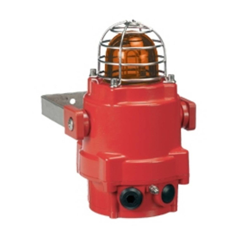
Pfannenberg
Pfannenberg BExBG05D-P User manual
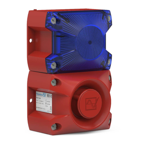
Pfannenberg
Pfannenberg PA L 1 User manual
Pfannenberg
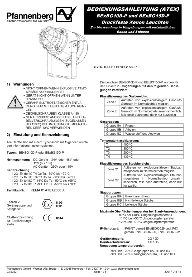
Pfannenberg BE BG10D-P Series User manual
Pfannenberg
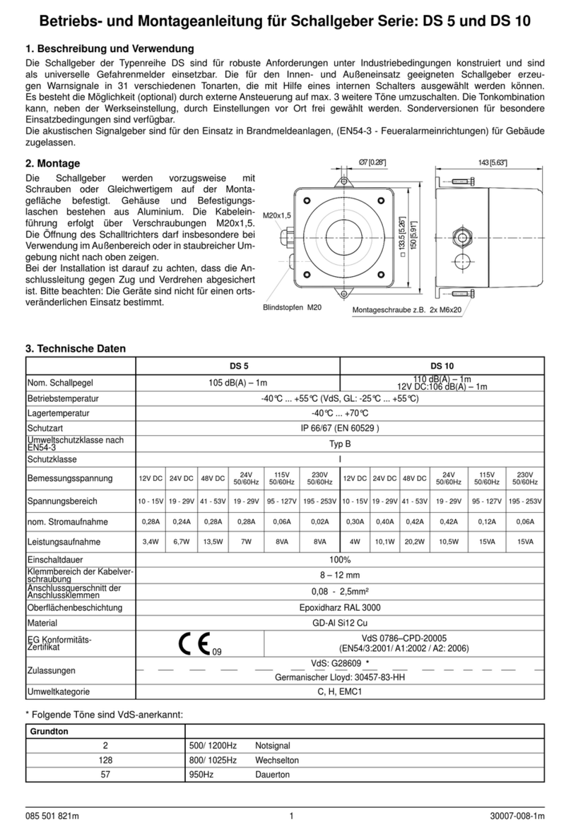
Pfannenberg DS Series Instruction Manual
Pfannenberg
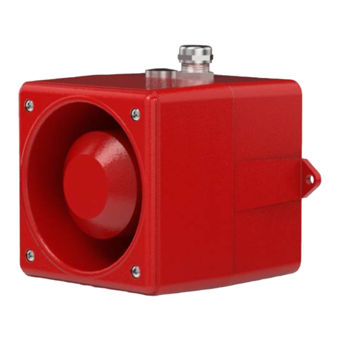
Pfannenberg DS Series Instruction Manual
Pfannenberg
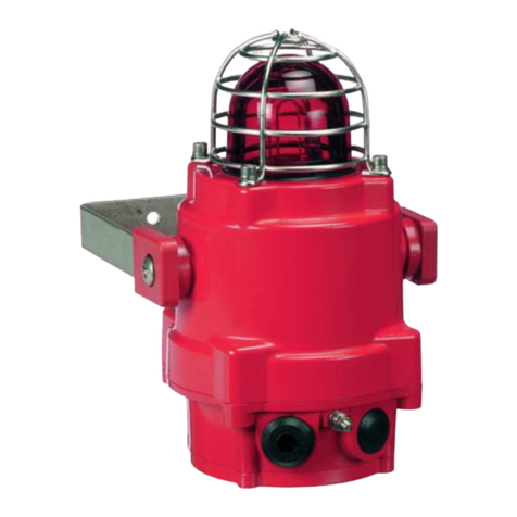
Pfannenberg BExBG15E-P User manual
Pfannenberg
Pfannenberg PY L-S User manual
Pfannenberg
Pfannenberg DS Series Instruction Manual
Pfannenberg
Pfannenberg Quadro LED-RGB-3G/3D User manual
Pfannenberg
Pfannenberg PA X 1-05 Assembly instructions
