Pfeiffer Vacuum DPG 109 User manual

Operating Instructions
DPG 109
PG 0005 BEN/F (1102)
Controller

2
1. Safety Instructions...................................................................... 3
1.1. For Your Orientation.............................................................................................4
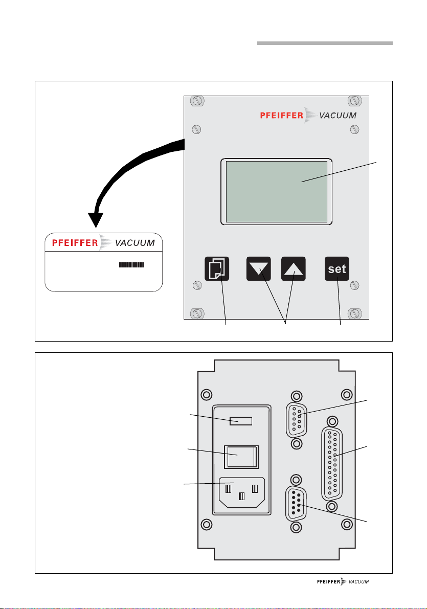
2. Understanding The DPG 109 ...................................................... 5
2.1. Main Features .....................................................................................................5
Proper Use ......................................................................................................... 6
Improper Use ..................................................................................................... 6
2.2. The Delivery Content .........................................................................................6
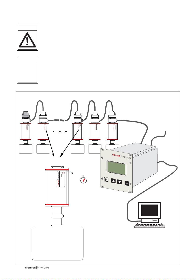
3. Installation .................................................................................. 7
3.1. Preparations For Installation............................................................................... 7
3.2. Connections ....................................................................................................... 7
3.2.1Mains Connection................................................................................................ 7
3.2.2.Transmitter Connection....................................................................................... 8
3.2.3 PC Connection (RS 232) ..................................................................................... 9
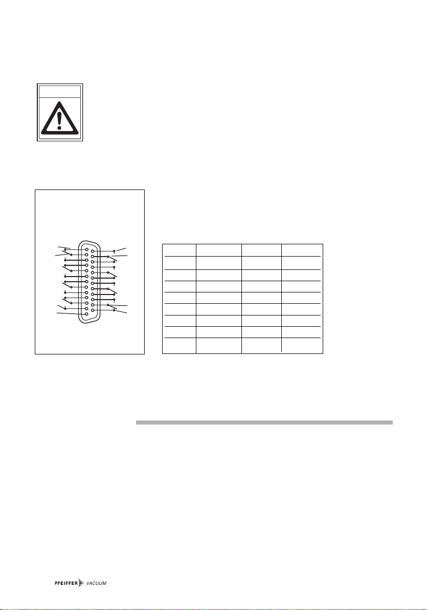
3.2.4.Relay Output ..................................................................................................... 10
4. Operations ................................................................................ 11
4.1. First-Time Operation......................................................................................... 11
4.2. Switching On The Unit.......................................................................................12
4.3. Measuring Mode.............................................................................................. 12
4.4. Configuration Mode (Overview Of Menu Options) .......................................... 12
4.5. General Procedure For Parametering ............................................................... 14
4.5.1. Menu «PRESSURE» ........................................................................................ 15
4.5.2.Menu «CHANNEL MENU»............................................................................... 17
Gas Type Correction Factor («CHANNEL MENU»)........................................... 18
Retro Adjustment («CHANNEL MENU») ......................................................... 19
4.5.3. Menu «CHANNEL MENU» .............................................................................. 20
Degassing («CHANNEL MENU»)..................................................................... 21
4.5.5 Menu «RELAY MENU» .................................................................................... 22
4.5.6.Menu «COMMON MENU» .............................................................................. 24
4.6 Communication Via RS 232 Interface............................................................... 25
5. Error Signals ............................................................................. 27
6. Maintenance, Service................................................................ 28
7. Technical Data .......................................................................... 29
7.1. Data Listings .....................................................................................................29
7.2. Dimensions Diagram........................................................................................ 29
8. Accessories ............................................................................... 30
9. Supplementary Information ..................................................... 30
Declaration Of Conformity .............................................Appendix
Index
Page
Please note
Current operating instructions are available via www.pfeiffer-vacuum.net

3
☞Read and follow all the instructions in this manual.
☞Inform yourself regarding:
– Dangers which can be caused by the unit,
– Dangers which can be caused by the system.
☞Observe the safety and accident prevention instructions.
☞Check regularly that the safety procedures are being complied with.
☞Take into account the prevailing environmental conditions when installing the
DPG 109.
☞The protection type is IP 20.
☞Take account of the relevant instructions when handling the process media and
observe the safety procedures.
☞Take account of the possible reactions between materials and process media.
☞Take account of possible reactions in the process media resulting from the
spontaneous warming of the product.
☞Do not carry out any unauthorized modifications to or conversions on the unit.
☞When returning the unit to the manufacturer please follow the shipping instructions.
☞Before beginning work, inform yourself regarding the existence of any possible
contamination.
☞When handling contaminated parts observe the relevant instructions and follow the
safety procedures.
☞Ensure that all other users receive the safety instructions.
Validity
These operating instructions describe the installation and operation of the Digital Vacuum
Measurement And Control Unit DPG 109 with the article number PT G15 010. The article
number appears on the rating plate.
To ensure the avoidance of possible product identification errors in any correspondence with
Pfeiffer Vacuum please always state the article number appearing on the rating plate.
This document is based on the component software version 1.50.
Technical modifications reserved.
1. Safety Instructions

4
1.1. For Your Orientation
Abbreviations used:
HPT = Digital Pirani/Bayard-Alpert Transmitter
CPT = Digital Piezo Transmitter
RPT = Digital Piezo/Pirani Transmitter
PPT = Digital Pirani Transmitter
MPT = Digital Pirani/Cold Cathode Transmitter
DPG = Controller
DPS = Power Supply
KK = Cold Cathode
Working instructions in the text,
➡Here you have to do something.
Pictogram Definitions
Important note.
☞
PLEASE NOTE
Danger of damage to the pump or system.
CAUTION
Danger of personal injury.
WARNING
Danger of an electric shock.
WARNING

5
Gauge
F1 T 2,0A
X1
S1
0
I
RS 232
Connection Side DPG 109
5 Unit fuse, 2 AT
6 Mains switch
7 Mains connection
8 Transmitter input;
SubD box (9 pole)
9 Relay output; SubD box
(25 pole)
10 PC connection; SubD plug
(9 pole)
5
6
7
8
9
10
DPG109
Product Identification on the rating
plate
Mod.:
Mod. No.:
Input:
Output.
Weight:
Ser. No.: 42000303
DPG 109
PT G15 010
.....V, 50/60Hz ..VA
.....V, 0.2 A
.....kg
D-35614 Asslar
1
243
Front Panel DPG 109
1 Display for
- Pressure measurement values
- Switch threshholds, hysteresis
- Units of measurement
- Relay preselection etc.
2 Menu key
3 Set key
4 Up/Down key
2. Understanding The DPG 109
2.1. Main Features

Proper Use
The DPG 109, in conjunction with the DigiLine Vacuum Transmitters, to measure and control
total pressures. The unit is ready for connection to up to 9 transmitters of Type CPT 100,
RPT 100, PPT 100, HPT 100 und MPT 100.
All products used in this connection must be operated in accordance with their operating
instructions.
Connect only original Pfeiffer Vacuum accessories.
Of a maximum of 9 connected transmitters only a mximum of 4 HPT 100-
Transmitters can be operated on the DPG 109. Otherwise the transmitter types
can be combined as required.
All products in use must be operated in accodance with the respective operating instructions.
Improper Use
The following is regarded as improper:
– The use for purposes not covered above, in particular:
– the connection to components which is not permitted according to their operating
instructions;
– the connection to components which contain touchable, voltage carrying parts.
No liability will be accepted for claims arising from improper use.
The user bears the responsibility with respect to the process media.
2.2.The Delivery Content
The following positions are included in the delivery consignment:
– DPG 109 PT G15 010
– Mating plug for the relay output
– Operating Instructions PG 0005 BN
The mains cable is not included in the delivery.
☞
PLEASE NOTE
6

7
3.1. Preparations For Installation
Do not carry out any unauthorized conversions or modifications on the unit.
Before connecting to local mains power:
The voltage stated on the rating plate of the DPG 109 must comply with local
mains voltage values.
Only use this controller where the:
Temperature is in the range: +5°C - +40°C.
Relative humidity is in the range: 5 - 85%, non dew forming.
Atmospheric pressure is in the range: 86 kPa - 106 kPa
3.2. Connections
The mains plug may only be plugged into a socket with protective contacts.
Use only 3 pole mains cable with proper protective earth connection. The
protective earthing may not be replaced by an extension lead without
protective earthing. The mains cable should be connected before all other
cables in order to ensure continuous earthing.
CAUTION
WARNING
If the unit is to be fitted into a rack, mains voltage must be
supplied via a terminal box.
0
I
3. Installation
3.2.1 Mains Connection
The mains plug may only be plugged into a socket with protective contacts.
Use only 3 pole mains cable with proper protective earth connection. The
protective earthing may not be replaced by an extension lead without
protective earthing. The mains cable should be connected before all other
cables in order to ensure continuous earthing.
WARNING

8
3.2.2 Transmitter Connection
The display unit must be switched off when a transmitter is connected. Non
observance of this instruction can lead to the unit being damaged.
Set the address selection switch on the transmitter rating plate to the desired
address 1 to 9 (RS485); for each sensor a different address.
Connect to the DPG 109 a maximum of 9 digital total pressure transmitters of the
DigiLine Program (thereof a maximum of 4 HPT100).
☞
PLEASE NOTE
CAUTION
RS 485
90...264 VAC
Mod.:
Mod.-No.:
Input:
Output.
Weight:
Ser.-No.:42000303
RPT100
PT.........
.....V,50/60Hz ..VA
.....V,0.2 A
.....kg
D-35614Asslar
Mod.:
Mod.-No.:
Input:
Output.
Weight:
Ser.-No.:42000303
PPT100
PT.........
.....V,50/60Hz ..VA
.....V,0.2 A
.....kg
D-35614Asslar
Mod.:
Mod.-No.:
Input:
Output.
Weight:
Ser.-No.:42000303
PPT100
PT.........
.....V,50/60Hz ..VA
.....V,0.2 A
.....kg
D-35614Asslar
Mod.:
Mod.-No.:
Input:
Output.
Weight:
Ser.-No.:42000303
PPT100
PT.........
.....V,50/60Hz ..VA
.....V,0.2 A
.....kg
D-35614Asslar
Mod.:
Mod.-No.:
Input:
Output.
Weight:
Ser.-No.:42000303
CPT100
PT.........
.....V,50/60Hz ..VA
.....V,0.2 A
.....kg
D-35614Asslar
D
PG
109
Vacuum
Chamber
Vacuum
Chamber Vacuum
Chamber
Vacuum
Chamber
PC
PC
RS 232/
SPS
Connection overview
CPT,
RPT,
PPT,
HPT
Vacuum
chamber
RS 485
Trans-
mitter
Mod.:
Mod.-No.:
Input:
Output.
Weight:
Ser.-No.: 42000303
PPT 100
PT.........
.....V, 50/60Hz ..VA
.....V, 0.2 A
.....kg
D-35614 Asslar
RS 485

9
1
2
3
4
5
6
7
8
9
3.2.3 PC Connection (RS 232)
This connection enables the DPG109 to be connected to the PC or PLC for the documentation
of pressure movements. The necessary Software "DokuStar" or "DokuStar Plus" (PT 882 501 -
T) and the connecting cable PT 348 130-T are available as accessories (please see Section 8.
Accessories).
Pin Arrangement SubD plug, 9 pole
Pin 1,4,6,7,8,9: n.c.
Pin 2: RXD
Pin 3: TXD
Pin 5: GND
Pin Arrangement SubD socket, 9 pole
Pin 1, 2, 3, 4, 9: n.c.
Pin 5: GND
Pin 6: VCC
Pin 7: RS 485, D-
Pin 8: RS 485, D+
Transmitter Connection
socket
Connecting The Transmitter:
➡Connect the first transmitter using a suitable data cable (Type PT 348 4xx; Bus cable) o the
unit socket ("Gauge"); always connect the double plug of the bus cable onto the
transmitter.
➡Connect the second transmitter with a second bus cable onto the double plug of the first
transmitter; take account of the address setting on the address selection switch.
➡Connect further transmitters in the ame manner.
➡Always provide the last transmitter with a closing resistor (see Accessories).
1
2
3
4
5
6
7
8
9
PC Connection plug
Connect the serial interface to the RS 232
pinout connector on the back of the unit by
means of a shielded cable (electromagnetic
compatibility).
Reference to the operating instructions
PM 800 488 BN for detailed information.
CAUTION

10
4. Operations
3.2.4 Relay Output
This output is used for the external control of the switching functions of the DPG 109.
For this purpose eight relay switchpoints (polarized contacts) are available.
Use the mating plug which is provided. Connect and disconnect the plug only in
a voltage free condition.
Load the outputs with a maximum of 3A only.
CAUTION
Relay Outputs SubD Box, 25 pole
Representation of the contacts when at rest, that means.:
Switch function = “OFF”
1
2
.
.
.
12
13
14
15
.
.
.
24
25
Relay Common Off On
K1 18 19 17
K2 15 16 14
K3 2 1 3
K4 5 4 6
K5 8 7 9
K6 11 10 12
K7 24 25 23
K8 21 22 20
Commands and numeric values are entered via 4 foil keys with detectable pressure point..The
display of the data and the user guide is presented in clear text via an illuminated graphic
screen. A flashing cursor marks the current input position. Set values to be saved must be
confirmed with the "set" key, otherwise the altered value is rejected and the original value will
be re-displayed („Undo" function)
Set values and configuration data are saved without temporal limitation .

11
4.1. First-Time Operations
Before switching on it must be ensured that the operating voltage which has
been set on the unit complies with local mains voltage and also that the protec-
tion lead connection has been made.
Check that the unit is earthed and also for correct installation of connecting
lines and transmitter.
The connected transmitter requires a warm up phase of at least 5 minutes.
Before the transmitter is equalized do not subject it to larges pressure
fluctuations.
☞
PLEASE NOTE
CAUTION
The DPG 109 carries out a self-test:
- The software version number
appears in the display.
- The connected total pressure trans-
mitter is identified automatically.
- Before the final switch off, the
actual parameters are activated.
- The start menu "PRESSURE" with
representation of the actual pressu-
re value appears in the display.
Switching off:
The DPG 109 can be switched off in any
operations mode.
The keyboard lock is activated (indicated
with a lock sign) until the DPG 109 is swit-
ched off.
1005
PRESSURE
ch: 1
rel.: 12 3 4 5 6 7 8
mbar
4.2. Switching The Unit ON/OFF
The mains switch is located on the rear panel of the unit (see Fig. in Section 2.1).
After switching on:
v 1.50
Scan
keyboard lock

12
»PRESSURE«
After switching on, the DPG109 is in the
start menu "PRESSURE". Here, the pressure
value with the respective channel number,
the unit and the setting of the 8 switching
relays are displayed.
»CHANNEL MENU«
This menu shows specific data for the selec-
ted channel (transmitter type, gas type and
correction factor).
In addition there is also the function to
select »adjust« for the respective sensors .
4.3. Measuring Mode
In the measuring mode the DPG 109 shows the currently measured pressure of the transmitter
which is connected. Depending on the pressure range, the display is represented either
numerically or exponentially.
The switch outputs are controlled according to the set switching parameters and actual pres-
sure.
A flashing pressure display or a flashing type display means that the communication with the
transmitter has been interrupted. In such a case re-initialize the unit by renewed depression
of the menu key.
4.4. Configuration Mode (Overview of Menu Options)
The configuration mode on the DPG 10 is attained via the menu key. There, the following para-
meters can be set successively.
type: RPT100
gas: N2/02/CO/Air
corr: 1.0
adjust
CHANNEL MENU
ch: 1
1005
PRESSURE
ch: 1
rel.: 12 3 4 5 6 7 8
mbar

13
»RELAY MENU«
Here is displayed the respective parameters
for the selected relay (channel assignment,
set value and hysteresis with unit). The
current setting of the 8 switching relays is
also displayed.
»COMMON MENU«
Here is the selection of the unit of pressure
and the pressure display type. In addition,
there is the option to switch on and off the
screen background lighting (the lighting is
always activated when the unit is switched
on).
type: HPT 100
BAFil: on
SWMode: trans_HI
degas: off
SENSOR MENU
ch: 1
chann: 1
press: 10 mbar
hyst: 1.0 mbar
RELAY MENU
rel: 1
pressure unit: mbar
display type: digit
backlight: on
COMMON MENU
12 3 4 5 6 7 8
»SENSOR MENU«
Here is displayed the specific sensor data
(type of transmitter, sensor setup and the
switching values of the combi transmitters)
of the current channel.
The function »degas« is only possible on
total pressure transmitters using the hot
cathode measuring system.

14
4.5 General Procedure For Parametering
As described in section 4.4. five basic menus are available for parametering.
The following example will show how to operate the various commands and keys:
“Menu“ key:
Switching over to the next menu
(see section 4.4.)
“Up/Down“ keys:
Alters the configuration data; a
flashing cursor marks the
current input position.
“set“ key:
Saves the edited values. Confi-
guration data are saved, with no
temporal limitation.
“Menu“ key:
Jumps a menu or rejects the
actual value (displayed by a
flashing cursor).
set
...... MENU
rel: ._
................
...................
...................
........._......
...................
...................
................
........._.......
...................
set
set
set
12 3 4 5 6 7 8

15
4.5.1 Menu «PRESSURE«
Menu name
Channel number
Actual pressure value (in large type format)
und unit of pressure.
Setting of the 8 switching relays (small
digits: „off“, large digits „on“.
Menu name
Actual pressure values of all 9 channels
simultaneously in small type format:
Format options:
p> 10 mbar: 4 positions e.g. 980 mbar
10> p> 1 mbar: 2 positions, one
position after the decimal point
e.g. 2.7 mbar
p< 1 mbar: 2 position mantissa,
1 position exponent with
pre-sign e.g. 5.6 x10⁻⁷
Pressure display of a selected channel as a
bar graph.
The pressure display follows here in the
form of a bar graph in large type format. The
exponent of the current pressure value
determines automatically the representation
range.
1005
PRESSURE
ch: 1
rel.:
mbar
PRESSURE
1 2 3 4 5 6 7 8910
ch: 1
rel.:
102mbar 103
PRESSURE
1: 1005
2: 980
3: 1.5E-5
4: 2.5E-9
5: 1
rel.: 12 3 4 5 6 7 8
mbar
1: 1.5
2: 10
3:notr
4:notr
In the »PRESSURE« menu the DPG 109 shows the currently measured pressure of the
transmitter which is connected. The switching outputs are controlled according to the set
switching parameters and the current pressure.
As illustrated below, there are 3 different types of display for the representation of the measu-
rement values (see section 4.5.4 Menu »COMMON MENU«/»display type«):
12 3 4 5 6 7 8
12 3 4 5 6 7 8
Exponent Mantisse
Einstellung: "digit":
Einstellung: "multi":
Einstellung: "graph":

16
»notr«:
The unit was not able to communicate with a
transmitter.
Causes:
1) No transmitter is connected.
2) The address selection switch of the
transmitter has not been set on a 485
Address between 1 and 9..
3) The data line between the DPG 109 and
transmitter is not correctly connected or
is faulty.
4) The unit serial interface in the DPG 109 is
defective.
»ur/or«:
The measured pressure is outside the
measurement range of the transmitter.
»Err1«:
The connected transmitter is defective.
»< 11..00··1100--44«:
With this display the filament is switched off
with the HPT and/or the KK sensor with the
MPT.
The measured pressure with the Pirani
sensor is currently < 1.0 · 10-4 (“UR” of the
Pirani sensor).
If the pressure rises in the Pirani sensors
measuring range , the value is measured and
displayed.
Further Display Options:
notr
PRESSURE
ch: 9
rel.:
mbar
12 3 4 5 6 7 8
ur/or
PRESSURE
ch: 9
rel.:
mbar
12 3 4 5 6 7 8
Err1
PRESSURE
ch: 9
rel.:
mbar
12 3 4 5 6 7 8
< 1.0 · 10-4
PRESSURE
ch: 1
rel.:
mbar
12 3 4 5 6 7 8

17
4.5.2 Menu «CHANNEL MENU«
This menu shows specific data for the selected channel (transmitter type, gas type and
correction factor). In addition the function »adjust« is selectable for the respective sensor.

18
ch: Channel number
CHANNEL MENU:Menu name
type: Identified transmitter type on
channel 1 (e.g. HPT 100)
gas: Set gas type for the actual
transmitter.
corr: Pre-set correction factor for the
actual transmitter.
adjust: Adjust.
Setting options for the correction factors:
1. Pre-programmed gas types.
The following gas types are selectable:
N2 / O2 / CO / Air / CO2 / H2 / Freon12 / He
/ Ne / Ar / Kr / Xe / user
➡Select the required gas type with
“Up/Down“ in the menu point »gas«; the
relevant correction factor will be display-
ed automatically in the menu point
»corr«.
2. Individual correction factor.
➡Select user specific correction factor
with “Up/Down“ in the menu point »corr«.
After altering a pre-programmed correction
factor under the menu point »gas« the
display will change tof »user«.
➡To carry out gas specific correction
range; Enter the factor in the range from
0.2 – 8.0.
Gas Type Correction Factor «CHANNEL MENU«
On total pressure transmitters (PPT 100, RPT 100) which employ a measuring method which is
independent of the type of gas, oonneecorrection factor for matching to various gases can be
assigned to the transmitter. This will ensure that the pressure display is corrected in a broad
pressure range. On a combi-transmitter such as the HPT 100 and the MPT 100 with differing
measurement methods ttwwoocorrection factors are necessary (see the operating instructions
for the transmitter).
type: HPT100
gas: N2/02/CO/Air
corr: 1.00PI 1.0 0BA
adjust
CHANNEL MENU
ch: 1
...
gas: N2/02/CO/Air
corr: 1.00
...
...
gas: user
corr: 2.00
...
set
set
set

19
Retro-Adjustment «CHANNEL MENU«
With the help of the DPG 109 retro-adjustment can be carried out on the transmitter.
When carrying out a zero point equalization ensure that the pressure in the vacuum chamber
is at least one decade below the measuring range of the transmitter.
The connected transmitter
requires a warm up phase of at
least 5 minutes. Do not subject
the transmitter to large pressu-
re fluctuations before
equalization.
➡Depress “set“ key until the cursor flashes
in the menu point »adjust«.
➡Depress the “Up“-key; in the display
there appears on the cursor position the
display »HI«.
To equalize the transmitter to
the daily pressure ensure that
the pressure on the transmitter
is between 800 and 1200 mbar.
➡After depressing the “set” key there
appears in the display the pre-set
reference pressure value (*)/(**).
➡With the “Up-/Down“ keys set the actual
reference day pressure (**).
➡By depressing the “set“ key the new
value is taken up, indicated through
»OK«, and the cursor jumps back to the
actual channel number »ch:«.
Appears »not OK« in the display, the
transmitter could not be adjusted.
➡Set the reference pressure value in the
same way for the zero point equalization
»LO«.
When equalizing to the zero
point »LO« ensure that the
reference pressure in the
vacuum chamber is at least
one decade below the measu-
ring range of the transmitter.
☞
PLEASE NOTE
☞
PLEASE NOTE
☞
PLEASE NOTE
set
...
gas: ...
corr: ...
adjust: HI/LO
...
gas: ...
corr: ...
adjust:HI 995 mbar
LO
LO
HI
HI
set
set
...
gas: ...
corr: ...
adjust:_
CHANNEL MENU
ch: 1
(*) The reference pressure value can only be entered
in the measurement units mbar, hPa or Torr. If, for
example the unit bar is selected, for reference
pressure input purposes there is a temporary switch
over to mbar, withTorr to Torr and with Pa to hPa.
When equalization has been completed the originally
selected display unit is again active.
(**) These points are only required for daily pressure
equalization on the CPT100 and the RPT100 .

20
4.5.3 Menu «SENSOR MENU«
Type dependant functions of the combi transmitters RPT 100, HPT 100 and MPT 100 can be
selected in this menu; described by the example HPT 100.
➡Depress the “set“ key in "SENSOR MENU"
until the cursor in the menu point »BAFil«
flashes; the actual status of the function
will be displayed (»off« or »on«).
With the transmitter MPT 100 there
appears »CCSens« instead of »BAFil«.
➡Using the “Down“ key select the function
»off«.
➡Confirm with the „set“ key.
➡Process dependent, it is possible to switch
on and off the filament of the BA
component (at HPT 100) as well as the KK
sensor (at MPT 100).
➡Depress the “set“ key in "SENSOR MENU"
until the cursor in the menu point
»SWMode« flashes; the actual status of
the function will be displayed
(»trans_Hi«, »trans_Lo« or »switch«),
depends on the type of transmitter.
➡Using the “Up/Down“ key select the desi-
red function.
➡Confirm with the „set“ key.
...
BAFil: on
...
...
...
...
SWMode: trans_HI
...
set
set
...
...
...
degas: off
set
type: HPT 100
BAFil: on
SWMode: Trans_HI
degas: off
SENSOR MENU
ch: 1
set
The function »degas« is only possible for
total pressure transmitters with the hot
cathode measuring system (HPT 100).
Table of contents
Other Pfeiffer Vacuum Controllers manuals

Pfeiffer Vacuum
Pfeiffer Vacuum Tele TC cable 110 User manual

Pfeiffer Vacuum
Pfeiffer Vacuum CenterOne User manual

Pfeiffer Vacuum
Pfeiffer Vacuum DPG 202 User manual

Pfeiffer Vacuum
Pfeiffer Vacuum TCP 600 User manual

Pfeiffer Vacuum
Pfeiffer Vacuum IMG 400 User manual

Pfeiffer Vacuum
Pfeiffer Vacuum TPS 110 User manual

Pfeiffer Vacuum
Pfeiffer Vacuum TCM 1601 User manual

Pfeiffer Vacuum
Pfeiffer Vacuum OPS 100 User manual

Pfeiffer Vacuum
Pfeiffer Vacuum MaxiGauge TPG 256 A PT G28 760 User manual

Pfeiffer Vacuum
Pfeiffer Vacuum TCP 120 User manual