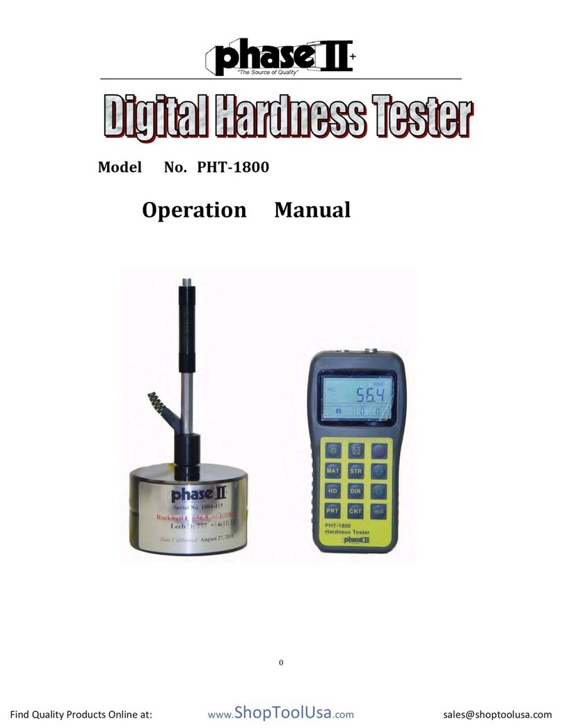
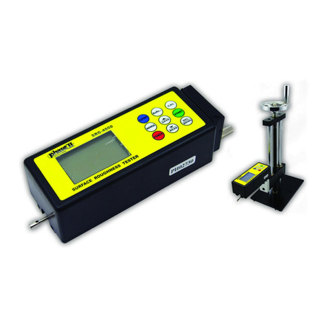
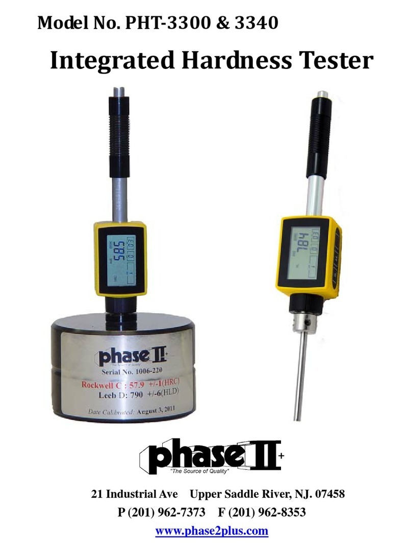
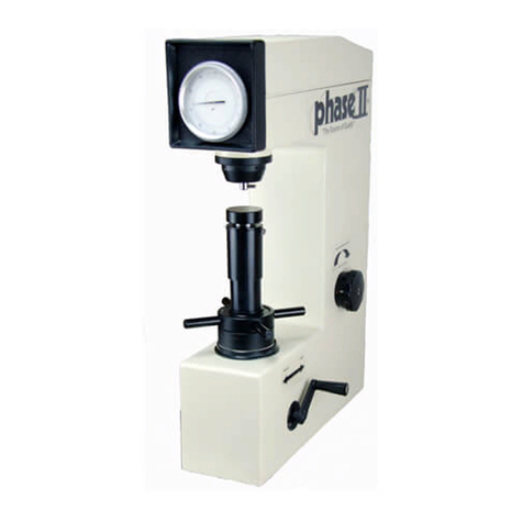
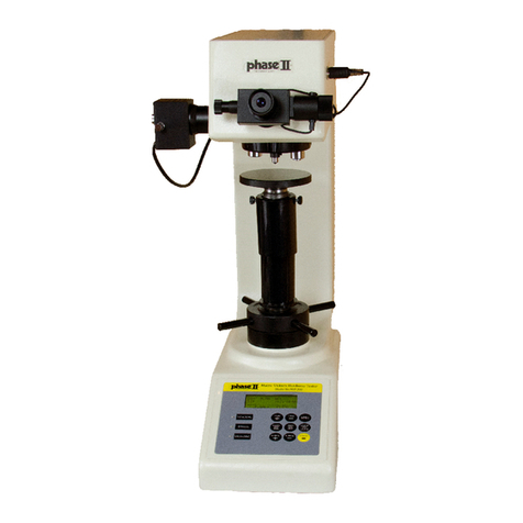
phase II+ 900-356 User manual

21IndustrialAve UpperSaddleRiver,NJ.07458
Tel:(201)962‐7373 Fax:(201)962‐8353
E‐Mail:info@phase2plus.com
WebSite:http://www.phase2plus.com
ModelNo.900‐355
ModelNo.900‐356
Shownw/OptionalOpticalScannerSystemPHT‐5000
BrinellHardnessTester

1
Contents
1 General description…………………………………………………………... 2
2 Key performance parameters………………………………………………. 2
3 Basic configuration and structure…………………………………………. 2
3.1 Standard configuration………………………………………………………. 2
3.2 Structure schematic diagram……………………………………………….. 3
4 Installation and adjustment…………………………………………………. 3
5 Operating methods…………………………………………………………… 4
5.1 Testing preparation…………………………………………………………… 4
5.2 Test parameters setting……………………………………………………… 5
5.2.1 Brinell hardness symbol ……….…………………………………………… 5
5.2.2 Load dwell setting…………………………………………………………….. 6
5.2.3 Reference information ………………………………………………………. 7
5.2.4 Time setting……………………………………………………………………. 7
5.3 Testing………………………………………………………………………….. 8
5.4 Shut down………………………………………………………………….…... 9
6 Maintenance and attentions………………………………………………… 9
Annex 1 Installation Notes……………………………………………… 11

2
1Generaldescription
The 900‐355/356 Brinell hardness testers are mainly used for hardness
determination for metallic materials such as cast iron, steel profiles,
nonferrous metals and soft alloys, and also can be used for testing of hard
plastics, bakeliteandsomeothernonmetallicmaterials. Thisunitissuitable
for use in factories, workshops, laboratories, universities and research
institutes.
Thetesterconformsto:
ISO6506MetallicMaterials‐BrinellHardnessTest
ASTME‐10TestMethodforBrinellHardnessofMetallicMaterials
2Keyperformanceparameters
Testforce:3000kgf(29400N),1500Kgf(14700N),1000Kgf(9800N),750Kgf(7355N),
500Kgf(4900N),250Kgf(2452N),187.5Kgf(1839N),125Kgf(1226N),
100Kgf(980N),62.5Kgf(612.9N)
Loaddwellduration:2s~99s,canbesetandstored
TungstenCarbideBallindenter:10mm,5mm,2.5mm
Measuringrange: 3.18HBW~658HBW
Magnificationofthemicroscope:20X
Resolutioncapabilityofthemicroscope:0.005mm
TestingCapacity:900‐355230mminvertical,140mminhorizontal
TestingCapacity:900‐356430mm(w/largeanvil)450mm(w/smallanvil)
Dimensions: 900‐355 530mm×260mm×750mm
Dimensions:900‐356600mm×300mm×1000mm
Netweight:110kg(900‐355)165kg(900‐356)Gross205kg
Powersupply:singlephase,AC,110V,50~60Hz,4A
Thepowersupplycanberesetto220V.Pleasecontactthesupplierto
resetitaccordingtheloc alpowersupply.
OptionalCabinet/SupportStand

3
3 Basic configuration and structure
3.1 Standard configuration
Base machine 1
Standard block 125-350HBW10/3000 1
Standard block 125-350HBW10/1000 1
Ф10mm Tungsten Carbide Ball indenter 1
Ф5mm Tungsten Carbide Ball indenter 1
Ф2.5mm Tungsten Carbide Ball indenter 1
Mounting screws for indenter 1
Screwdriver for indenter mounting 1
Flat anvil 1
“V ”shape anvil 1
20X microscope 1
Power supply wire 1
Dust cover 1
3.2 Structure schematic diagram
1
1
2
3
4
6
5
1)Screen/Keypad
2)Penetrator
3)Anvil
4)ElevationScrew/Cover
5)Handwheel
6)LevelingFeet

21IndustrialAve UpperSaddleRiver,NJ.07458
Tel:(201)962‐7373 Fax:(201)962‐8353
E‐Mail:info@phase2plus.com
WebSite:http://www.phase2plus.com
4Installationandadjustment
4.1 Unpackthewoodcase,thenremovethethreeM10screwsfromtheundersideofthebase.Liftthe
machineverycarefullyfromthebottom.Removetheallaccessoriesthatareattachedtothe
baseboardbythestraps.
4.2 Themachineshouldbemountedonafirmbenchortableinacleanarea,freefromvibrationor
shock,recommendedheightis800mm.Aholemustbeprovidedinthetopofthebenchtoprovide
workingclearancefortheleadscrewreferingfigure4.1.
4.3 Placethetesteronthepreparedbench,turnthehandwheelcounterclockwisetolowertheanvil,
removetheantivibrationpad;thenplaceaprecisionlevelwiththeaccuracyof0.2mm/mon the
anvil,adjustthelevelingfeetoftestertomakethemachinelevelwithin1mm/m,thenlockthenuts
onthelevelingfeet.
Figure 4.1
4.4 Forinstallation,opentheuppercoverandbackcoveroftester, then remove all the
packing materials. Inspecttomakesurethebladeshouldbecorrectlyplacedinthe V
grooveasfigure4.2showing.(Thisisdoneatthefactorybutmaybeoutofadjustment
duetotransportationofmachine.)
Figure4.2
4.5 Reinstalltheupperandbackcoverandconnectthepowersupplywire.

4
5 Operating methods
5.1 Testing preparation
Switch on the machine and then the tester will automatically perform a self check. The relative
information such as type, series number, software version will be displayed on screen. Tester will
come to main menu after self-checking; current test parameters will be displayed on screen, and
the status at the last test parameters will be automatically stored.Figure5.1.1 isa typicalstatus of
Brinelltestingparameter;showingthetestingload,indenterdiameter,loaddwellduration,aswellas
currenttime.
Figure5.1.1
Theproperindentermustbemountedinthemachineaccordingtothespecificrequirementsofthe
hardnesstest.Wheninstallingindenter,makesuretheinstallingsurfacecleanandtightlyfixed.
Thetestcanbeperformeddirectlyaccordingtotheprocedure5.3ifnoneoftheparametersaboveis
requiredtomodify;followingproceduresshouldbeobservedifmodificationisnecessary.
5.2Testparameterssetting
5.2.1 5.2.2
Press “Setup” key, figure 5.2.1 will be shown on the display, the parameter setting is ready.

5
5.2.1 Brinell hardness symbol
There are 12 kinds of Brinell parameters that this machine is capable of setting. The appropriate
parameters should be selected according the material and intended hardness value. The
parameters are listed in Tab 5.1.
Press“ ”or“ ”key to move cursor to “1” in figure 5.2.1, press “ ” key ,then the cursor move
to “HB10/3000”. Press “ ”or“ ”key at this time the optional 12 Brinell symbols in Tab5.1 will be
appear in sequence. When the desired symbol appears, press “ ”to confirm. At this time test
force will be changed automatically.
Press “Setup” key to return to figure 5.1.1;or press “ ”or “ ”key to reset the other parameters.
Tab 5.1 Brinell hardness parameters
Hardness
symbols
Indenter
Diameter(mm)
Testing load, F Indention
(mm)0.102F/D2
(in kgf)(in N)
1 HBW10/3000 10 3000 29420
2.4mm-6.0mm
30
2 HBW10/1500 10 1500 14710 15
3 HBW10/1000 10 1000 9807 10
4 HBW10/500 10 500 4903 5
5 HBW10/250 10 250 2452 2.5
6 HBW10/100 10 100 980.7 1
7 HBW5/750 5 750 7355
1.2mm-3.0mm
30
8 HBW5/250 5 250 2452 10
9 HBW5/125 5 125 1226 5
10 HBW5/62.5 5 62.5 612.9 2.5
11 HBW2.5/187.5 2.5 187.5 1839
0.6mm-1.5mm
30
12 HBW2.5/62.5 2.5 62.5 612.9 10

6
5.2.2 Load dwell setting
Load dwell refers to the duration of total test force.
Press “ ”or“ ”key to move cursor to “2” in figure 5.2.2, press “ ” key ,then the cursor move
to “12S”. Press “ ”or“ ”key at this time to select the dwell time range from 2s~99s,then press
“”to finish the setting.
Press “Setup” key to return to figure 5.1.1;or press “ ”or“ ”key to reset the other parameters.
5.2.3 Reference information
Press “ ”or“ ”key to move cursor to “4” in figure 5.2.2, press “ ” key ,then the figure 5.2.3,
and 5.2.4 appear, which showing the directions for 0.102F/D2ratios should be selected
according to the materials and the range of hardness value.
Figure5.2.3 Figure5.2.4
Press “Setup” key to return to figure 5.1.1;or press “ ”or“ ”key to reset the other parameters.
5.2.4 Time setting
Press “ ”or“ ” key to move cursor to “6” in figure 5.2.1, press “ ” key, figure5.2.5 appears.
Press “ ”or“ ”key to move cursor to “1” in figure 5.2.12, then press “ ” key, press “ ”or“ ”
to select the year, and press “ ” key to confirm. The month, also the date, hour, minute and
second can be reset in the same way.
Press “Setup” key to return to figure 5.1.1.
Figure 5.2.5

7
5.3 Testing
Caution:The sample must be place and supported in such a manner that the surface to
be indented is in a plane perpendicular to the axis of the indenter and the line of the
indenting force. Otherwise 3000kgf will bring a great divisive force in horizontal direction
that may cause damage to the machine.
YES NO
Place the sample to be tested on the anvil, and rotate the hand wheel in clockwise to lift the anvil
as figure 5.3.1, showing the anvil moving course. Rotate the hand wheel smoothly until the anvil
in figure reaches the end position, buzzing warning will be given out, then the rotating should be
stopped at right.
Figure5.3.1 Figure5.3.2
Then the testing cycle will be performed automatically as following: load application showing as
figure 5.3.2, the load holding showing as figure 5.3.3 with dwell time counting down, finally
unloading is performed immediately when the dwell time has finished.
After that, all the test results will be shown on the display as in figure 5.3.4.
Rotate the hand wheel in counter-clockwise to lower the anvil, and the screen returns to figure
5.1.1 for the next test.

8
Figure5.3.3 Figure5.3.4
1
1.
.
Use of Microscope for Readings Taking
1.1 A scheme of the microscope’s external structure (Fig. 8)
Lens Cylinder Base
Long Lens Cylinder
Object Lens Cylinder
Lens Cylinder Locking Screw
Eye Lens Package
Eyelens Adjusting Knob
Reading Taking Drum
1.2 Application
This microscope is designed to be used primarily for measurement of the indent formed in Brinell hardness
test.
1.3 Technical Specification
Amplification: x 20; diameter of the sight range: 9 mm; effective measurement range: 6 mm
Eye lens scale span Graduation range of
eye lens scale
Minimum readable on
the micro-measuring
drum
Measurement
accuracy
1 mm 8 mm 0.005 mm 0.005 mm
Fig 8

9
1.4 Operation instructions:
1.4.1 Place the microscope on the standard block or specimen, using natural light or a lamp
as illumination through the notch on the long lens cylinder. Both the numerals and
graduation lines on the scale shall be clearly identifiable in the sight range. If the
indent can not be clearly defined, turn the eye lens knob to adjust the sight until it
becomes clear. The microscope is calibrated at the factory to make possible that
indents can be clearly defined.
1.4.2 Rotate the drum to take reading. Numerals from 0 – 90 and 100 graduation lines are
printed on the drum with the scale span of 0.005 mm so that a complete turn of the drum
equals to 0.5 mm. See Fig. 9 for details.
1.4.3 There are two graduation scales in the eye lens, one fixed and one mobile. Numerals
from 0 – 8 are indicated on the fixed scale with span of 1 mm (see Fig. 10 for detail),
while a black line is marked on the mobile scale for measurement.
1.4.4 When the drum starts to rotate, the mobile scale with black line moves simultaneously.
By this time the indent can be measured in the following manner: at first move the black
line to line up with one side of the indent and take the reading, then turn the drum and
shift the line to the other side of the indent and take reading accordingly.
Scheme of Graduation Lines on the Scale
Fig 10
Reading Drum
Fig 9
Indent Measurement Example
Fig 11

10
Measure the diameter of the indention using the microscope in 2 directions perpendicular to each
other. Remember the values and enter as shown below, marked as d1 and d2 on the digital
display of the machine
Press “ ”or“ ” key to move cursor to “3” HBW Calculator in figure 5.2.1, then press “ ” key
to confirm. Figure5.3.5 appears. Press “ ”or“ ”key to input the two diameters, d1 and d2. And
press “ ” key to confirm. The Brinell hardness value will be calculated automatically.
Figure 5.3.5
5.4 Shut down
Remove the test force completely, and switch off the power supply. Remove power cord when machine will not
be in use for an extended period of time.
6 Maintenance
6.1Whenthehardnesstesteristoberepositionedinanotherareaofyourfacility,theindentermustbe
removed.Ifitistobetransportedforalongdistance,theoriginalpackagingmustberestored.
6.2Whenperforminganyadjustments andexaminingin themachine,thepowersupplymustbeturned
off.
6.3Wheninstallingorremovingtheindenter,themountingsurfaceshouldbecleananddry.Theindenter
shouldberemovedcarefullyandplacedbackinitssuppliedcaseifnotbeingusedforanextendedperiodof
time.
6.4Thesurfaceofanvilandstandardhardnessblocksshouldbecleanwithoutcontamination,scratchesor
rust.Whenstoringanvilsortestblocks,theyshouldbelightlycoatedwithoiltopreventrusting.
6.5Dustproofandcorrosivemediumpreventionshouldbeconsideredindailyoperatingenvironment.Rust
preventionmeasuresshouldbeadoptedinhighhumidityarea.
6.6Theleadscrewoftheanvilshouldbelubricatedperiodically.Applyafewdropsoflightmachineoil,
thenruntheleadscrewupanddownafewtimestodistributetheoil.
6.7Pleasedon’tdisassembleoradjustanyfixedparts.Thiswillvoidyourwarranty.Thisshouldbedone
byaprofessionalservicepersonfamiliarwiththemachine.

11
PHT-5000 Brinell Hardness Indentation Auto-measurement System
Features
1. FriendlyUserInterface:Automaticmeasurementwithakeystrokeoraclickofabutton;
Testresultscanbemanuallygeneratedorcorrectedwithasinglem o u se dra g m ove ;
2. Highreliability:Advancedimageprocessingandanalysistechnologiesinautomatic
measurement.Fieldprovenunderseveresamplesurfaceconditions;
3. Singlecamerawithfourmagnifications:1.3MpixelCMOSUSBcamerawithtwocamera
tubeswitheachtubeheighthavingtwomagnifications.Fullmeasurementrangeiscovered
withfourmagnificationsforbettermeasurementaccuracy.Specifically, tube 1
magnification#1issuitableforindentationdiameters3~6mm,magnification #2 for
0.8~1.6mm,whiletube2magnification#3for2~4mm,andmagnification#4for1~2mm.
www.phase2plus.com
Shownw/laptop.(notincluded)

12
MainFunctions
1. BasicFunctions: Includes the basic functions of imaging system such as image capture,
camera calibration, image processing, geometric measurement, document labeling, and
albummanagement;
2. Automaticmeasurement: Automatically or manually measures the indentation diameter
andcalculatesthehardnessHBvalue;
3. HB2(DIN1605standard)automaticmeasurement:Automaticallyormanuallymeasures
theindentationdiametersonthecalibrationsampleandthetestsample,andautomatically
interpolatestheHBvalueforthetestsample;
4. Conversionandvalidation:ConvertsHBtootherhardnessscales;Validatesthetestresults
withsampledimensions;
5. Statistics:Automatically updates the statistical values such as average, minandmax,
standarddeviation,CpandCpk;
6. Auto‐alarm:Automaticallymarkstheoutofspecmeasurements;
7. Testreport:AutomaticallygeneratescustomizableWORDorEXCELreport.

13
ApproximateHardnessConversionNumbersforNon‐AusteniticSteels(RockwellCHardnessRange)A
BrinellHardnessNumberC Rockwell SuperficialRockwellNumber
RockwellC
150kgf
(HRC)
Vickers
(HV)
10‐mm
Standard
ball
3000kgf
(HBS)
10‐mm
Carbide
ball
3000kgf
(HBW)
Knoop
500‐gf
and
Over
(HK)
A
Scale
60kgf
(HRA)
DScale
100kgf
(HRD)
15‐N
Scale
15‐kgf
(HR15N)
30‐N
Scale
30‐kgf
(HR30N)
45‐N
Scale
45‐kgf
(HR45N)
Scleroscope
HardnessD
68
67
66
65
64
63
62
61
60
59
58
57
56
55
54
53
52
51
50
49
48
47
46
45
44
43
42
41
40
39
38
37
36
35
34
33
32
31
30
29
28
27
26
25
940
900
865
832
800
772
746
720
697
674
653
633
613
595
577
560
544
528
513
498
484
471
458
446
434
423
412
402
392
382
372
363
354
345
336
327
318
310
302
294
286
279
272
266
…
…
…
…
…
…
…
…
…
…
…
…
…
…
…
…
(500)
(487)
(475)
(464)
451
442
432
421
409
400
390
381
371
362
353
344
336
327
319
311
301
294
286
279
271
264
258
253
…
…
…
(739)
(722)
(705)
(688)
(670)
(654)
634
615
595
577
560
543
525
512
496
481
469
455
443
432
421
409
400
390
381
371
362
353
344
336
327
319
311
301
294
286
279
271
264
258
253
920
895
870
846
822
799
776
754
732
710
690
670
650
630
612
594
576
558
542
526
510
495
480
466
452
438
426
414
402
391
380
370
360
351
342
334
326
318
311
304
297
290
284
278
85.6
85.0
84.5
83.9
83.4
82.8
82.3
81.8
81.2
80.7
80.1
79.6
79.0
78.5
78.0
77.4
76.8
76.3
75.9
75.2
74.7
74.1
73.6
73.1
72.5
72.0
71.5
70.9
70.4
69.9
69.4
68.9
68.4
67.9
67.4
66.8
66.3
65.8
65.3
64.8
64.3
63.8
63.3
62.8
76.9
76.1
75.4
74.5
73.8
73.0
72.2
71.5
70.7
69.9
69.2
68.5
67.7
66.9
66.1
65.4
64.6
63.8
63.1
62.1
61.4
60.8
60.0
59.2
58.5
57.7
56.9
56.2
55.4
54.6
53.8
53.1
52.3
51.5
50.8
50.0
49.2
48.4
47.7
47.0
46.1
45.2
44.6
43.8
93.2
92.9
92.5
92.2
91.8
91.4
91.1
90.7
90.2
89.8
89.3
88.9
88.3
87.9
87.4
86.9
86.4
85.9
85.5
85.0
84.5
83.9
83.5
83.0
82.5
82.0
81.5
80.9
80.4
79.9
79.4
78.8
78.3
77.7
77.2
76.6
76.1
75.6
75.0
74.5
73.9
73.3
72.8
72.2
84.4
83.6
82.8
81.9
81.1
80.1
79.3
78.4
77.5
76.6
75.7
74.8
73.9
73.0
72.0
71.2
70.2
69.4
68.5
67.6
66.7
65.8
64.8
64.0
63.1
62.2
61.3
60.4
59.5
58.6
57.7
56.8
55.9
55.0
54.2
53.3
52.1
51.3
50.4
49.5
48.6
47.7
46.8
45.9
75.4
74.2
73.3
72.0
71.0
69.9
68.8
67.7
66.6
65.5
64.3
63.2
62.0
60.9
59.8
58.6
57.4
56.1
55.0
53.8
52.5
51.4
50.3
49.0
47.8
46.7
45.5
44.3
43.1
41.9
40.8
39.6
38.4
37.2
36.1
34.9
33.7
32.5
31.3
30.1
28.9
27.8
26.7
25.5
97.3
95.0
92.7
90.6
88.5
86.5
84.5
82.6
80.8
79.0
77.3
75.6
74.0
72.4
70.9
69.4
67.9
66.5
65.1
63.7
62.4
61.1
59.8
58.5
57.3
56.1
54.9
53.7
52.6
51.5
50.4
49.3
48.2
47.1
46.1
45.1
44.1
43.1
42.2
41.3
40.4
39.5
38.7
37.8

14
ApproximateHardnessConversionNumbersforNon‐AusteniticSteels(RockwellBHardnessRange)A
RockwellSuperficialRockwellNumber
RockwellB
100kgf
(HRB)
Vickers
(HV)
10‐mm
Standard
ball
3000kgf
(HBS)
Knoop
500‐gf
and
Over
(HK)
A
Scale
60kgf
(HRA)
FScale
60kgf
(HRF)
15‐T Scale
15‐kgf
(HR15T)
30‐T Scale
30‐kgf
(HR30T)
45‐TScale
45‐kgf
(HR45T)
100
99
98
97
96
95
94
93
92
91
90
89
88
87
86
85
84
83
82
81
80
79
78
77
76
75
74
73
72
71
70
69
68
67
66
65
64
63
240
234
228
222
216
210
205
200
195
190
185
180
176
172
169
165
162
159
156
153
150
147
144
141
139
137
135
132
130
127
125
123
121
119
117
116
114
112
240
234
228
222
216
210
205
200
195
190
185
180
176
172
169
165
162
159
156
153
150
147
144
141
139
137
135
132
130
127
125
123
121
119
117
116
114
1
12
251
246
241
236
231
226
221
216
211
206
201
196
192
188
184
180
176
173
170
167
164
161
158
155
152
150
147
145
143
141
139
137
135
131
129
127
125
124
61.5
60.9
60.2
59.5
58.9
58.3
57.6
57.0
56.4
55.8
55.2
54.6
54.0
53.4
52.8
52.3
51.7
51.1
50.6
50.0
49.5
48.9
48.4
47.9
47.3
46.8
46.3
45.8
45.3
44.8
44.3
43.8
43.3
42.8
42.3
41.8
40.9
40.4
…
…
…
…
…
…
…
…
…
…
…
…
…
…
…
…
…
…
…
…
…
…
…
…
…
99.6
99.1
98.5
98.0
97.4
96.8
96.2
95.6
95.1
94.5
93.9
93.4
92.8
93.1
92.8
92.5
92.1
91.8
91.5
91.2
90.8
90.5
90.2
89.9
89.5
89.2
88.9
88.6
88.2
87.9
87.6
87.3
86.9
86.6
86.3
86.0
85.6
85.3
85.0
84.7
84.3
84.0
83.7
83.4
83.0
82.7
82.4
82.1
81.8
81.4
81.1
83.1
82.5
81.8
81.1
80.4
79.8
79.1
78.4
77.8
77.1
76.4
75.8
75.1
74.4
73.8
73.1
72.4
71.8
71.1
70.4
69.7
69.1
68.4
67.7
67.1
66.4
65.7
65.1
64.4
63.7
63.1
62.4
61.7
61.0
60.4
59.7
59.0
58.4
72.9
71.9
70.9
69.9
68.9
67.9
66.9
65.9
64.8
63.8
62.8
61.8
60.8
59.8
58.8
57.8
56.8
55.8
54.8
53.8
52.8
51.8
50.8
49.8
48.8
47.8
46.8
45.8
44.8
43.8
42.8
41.8
40.8
39.8
38.7
37.7
36.7
35.7

15
ApproximateLeeb(TypeD)HardnessConversionforNon‐AusteniticSteels(RockwellCHardnessRange)A
LeebHardness,TypeD
ImpactDevice(HLD)
RockwellCHardness
150kgf(HRC)
VickersHardness
(HV10)
BrinellHardness
10mmSteelBall
3000kgf(HBS)
828
819
809
800
791
782
773
764
755
746
737
729
720
712
703
695
687
679
671
663
655
647
640
632
625
618
611
603
596
590
583
576
570
563
557
551
545
539
533
527
521
516
510
62
61
60
59
58
57
56
55
54
53
52
51
50
49
48
47
46
45
44
43
42
41
40
39
38
37
36
35
34
33
32
31
30
29
28
27
26
25
24
23
22
21
20
762
737
711
688
667
645
625
605
586
568
550
534
517
503
487
473
460
447
434
422
410
398
388
377
368
358
349
339
330
323
314
306
299
291
284
277
271
264
258
251
245
240
234
(721)
(699)
(675)
(654)
634
614
595
577
559
542
526
511
496
482
467
455
442
430
418
407
395
385
375
365
356
347
338
328
320
313
305
297
291
283
276
270
264
258
252
246
240
235
229

16
MainHeadquarters:U.S.A
PhaseIIMachine&Tool,Inc.
21IndustrialAve
UpperSaddleRiver,NJ.07458 USA
Tel:(201)962‐7373
Fax:(201)962‐8353
GeneralE‐Mail:info@phase2plus.com
www.phase2plus.com
MEXICO
PhaseIIde Mexico
CalleANo.4PromerPiso
Col.SanMarcosAzcapotzalco
C.P02020Mexico
Tel:01(55)3622‐7000
Fax: 01(55) 5319
‐
4000
BEIJING,CHINA
PhaseIIMeasuringInstruments(Beijing)Ltd.
Room 301, Bldg 2 Qing Yuan Xi Li, Haidian District,
Beijing100192,China
Tel:+86‐10‐59792409
Fax:+86‐10‐59814851
General E
‐
mail:
info@phase2china.com.cn
VENEZUELA
PhaseIIHerramientasUniversales
EDCM.CA.
Av.FranciscoLazoMartiCC
PlazaSantaMonicaPBLocal
SantaMonica,Caracas1040Venezuela
Tel:212‐690‐28‐21
Fax:212‐693‐29‐16
This manual suits for next models
1
Table of contents
Other phase II+ Test Equipment manuals

phase II+
phase II+ SRG 2200 User manual

phase II+
phase II+ MET-U1A User manual

phase II+
phase II+ 900-345 User manual

phase II+
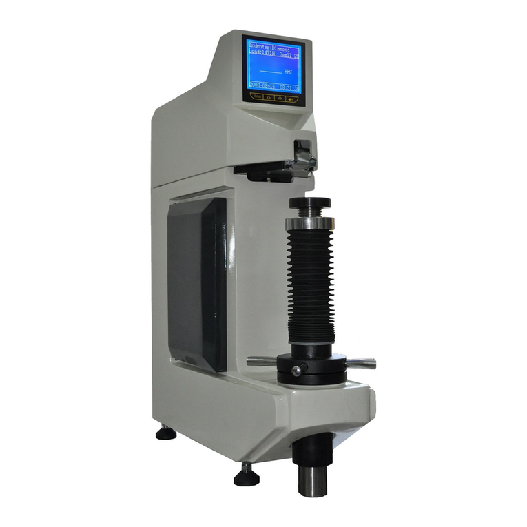
phase II+ 900-365 User manual

phase II+
phase II+ PHT-5000 User manual

phase II+
phase II+ PHT-1800 User manual

phase II+
phase II+ DVM-1000 User manual
phase II+
phase II+ 900-398 User manual

phase II+
phase II+ SRG-2000 User manual

phase II+
phase II+ SRG-4000 User manual