manuals.online logo
Brands
  1. Home
  2. •
  3. Brands
  4. •
  5. Philips
  6. •
  7. Measuring Instrument
  8. •
  9. Philips 22RR454/00 User manual

Philips 22RR454/00 User manual

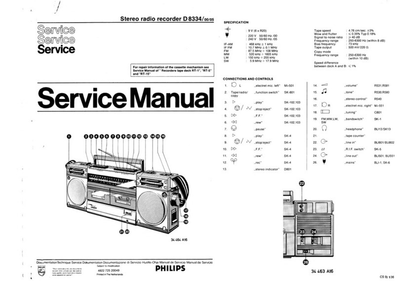
Radio-recorder
22RR454/00/15/19
Service
ervics
STOR
<K]
REC.
SKE
SK-A
@
<J
b>
eo
ary
SK-B
R420
SK-F
SKE
SK-E
”
AUT.STOP
LA
415
C401
b,c
.
Salt
at:
/OF/—_
S413
SK-L
LW-
MW-SW-FM
SK-K
0@/RADIOREC/
@
SK-H
&/rie
7
SK-J
FOO
©
110/220V~
QVs=
(6xR14)
Cea
|
0
eee
a:
oe
ae
eo
loH*
LW:
150-260kHz
(2000-1154m)]
«(00/28
:
452k
Hz
uy
MW:
520-1605
kH
1)
:
| .
:
520
Z
(576.3-
187.5m)
>
IF
—
15
2
668kHz
4.73
¢M/sec
:
SW:
5.95
-9.775MHz
(508
-30.9m
)
/19
+
460kHz
FM:
875-104
MHz
~
[F
$10.7
MHz
BQ-1W
sin
(d<10%)
oe
6929B
Safet
regulations
require
that
the
set
be
restored
to
its
original
condition
and
that
parts
which
are
identical
with
those
specified,
be
used.
‘Docu
mentation
Technique
Service
Dokumentation
Documentazione
di
Servizio
Huolte-Ohie
Manual
de
Servicio
Manual
de
Servicio.
PHILIPS
Subject
to
modification
CS$53334
4822
725
11609
Printed
in
The
Netherlands
Cabinet
Cassette
enveloppe
WRENCH
25mm
4822
395
50085
6943A
6945A
Fig.
A
|
Fig.
B
LF
unit
|
1
rn
Fig.
C
3
69488
LF
PC
board
HF
PC
board
5
5
5
5
5
aes
Ge
RO
ooo}
[}
Goocel
/
Cold
tol
Eo
eed
ze
2
3
69468
Fig.
D
Mounting
the
LF
unit
(Fig.
C)
-
Fit
connector
5.
-
Sluit
connector
5
aan.
-
Lower
the
LF
unit
into
the
cabinet,
taking
care
-
Laat
LF
unit
in
kast
zakken,
let
daarbij
op
juiste
that
the
position
of
components
A
and
B
is
correct.
posities
van
componenten
A
en
B.
-
Carry
out
procedures
4, 3,
2
and
1.
-
Verricht
daarna
de
handelingen
4,
3,
2
en
1.
CF)
Montage
de
l’unité
BF
(Fig.
C)
Cd)
Montage
der
NF.Einheit
(Abb.
C)
-
Brancher
te
connecteur
5.
-
Konnektor
5
anschliessen.
-
Laisser
descendre
|’unité
BF
dans
fe
boitier,
-
NF-Einheit
in
das
Gehause
senken;
achten
Sie
faire
attention
que
les
composants
A
et
B
soient
darbei
auf
die
richtige
Lage
der
Einzelteile
A
und
dans
la
bonne
position.
B.
-
Exécuter
ensuite
les
opérations
4,
3,
2
et
1.
.
-
Danach
sind
die
Handlungen
4,
3,
2
und
1
aus-
zufuhren.
C1)
Montaggio
dell’unita
BF
(Fig.
C)
-
Collegare
il
connettore
5.
-
Lasciare
scivolare
|’unita
BF
ingiu
nel
mobile
assicurarsi
che
i
componenti
A
e
B
siano
nella
posizione
giusta.
-
Quindi
procedere
alle
operazioni
4,
3,2e1.
pew
camer
tevmrtistaiy
Morte
sla
SE:
3
'
FR
Te
Se
Oe
REI
I
ET
ea
D403
D406
D459
TS401
TS402.0404
D405
TS425A
D467
_TS425B
D450
TS441A,B
TS425C
0451
D452A.8
MiSC|-
_15630,429.431,432
LA4IS
0461,462
M0460
K1,2
TS.437.0464.455
TS434,435
TS438
D454...456
TS443
TS442
TS439
TS440
D468
D469
D470
TS446
TS645
D472.471
VL1
MISC
410
480.411
411
412
413
414
415
482,483
486,494
495
487.496
LS409
489.497
490
407
509.419.505.420
421422423
427 428
429
4633.426,432430
431
779
434
435
L01c
506
507.519
523.518.521
528.525.524.520.517522
529.545.546.548526.547_
541
530
549
551.
536.550.818.552
542
531
553
555.532
556
538
533.534.557.535.537
558
loib
512
«519-776
-775:510773.511
_514.771.772
770
781
782.
783
784
785786,.780,787799---801789
790.797.798
788
796
808
809,805806.811,807812810.804
820
554.544
_—815
817.828.819.821
814
813.816.822
829
830.831
827
826
832
B34
833
|
R
439
440
441.880
879.443
644.844
845
&46.851.853
850
866
865
867.958.868.
959.956.855,869.854
957
856.870.955.954
872.871
852857
B63
873.858.874.861
860.859.864875.862|
R
|
TR
|
842
904906
896-898
901.905.895.900
__
899.847.849.890:
694
909.910.924.925
931.911
932
930.916.926
919.915.927,929.917.914.918928
939.938.943
937.942.940.420941
935
936
878
948.950
946.947.951963.965.949972
962.964.945.966.
944
967
973.974
968.976
975
|
rR
|
R862
470k
cs
C530
C531
_R852
IF-FM
:
10.7MHz
pa
a
ene
Se
=
=
|
Reet
IF-AM
:/00,/28
:
£52kHz
10p
5.6p
Beer
D452a
R858
/15
:
668kHz
CH
&
15.2550)
3
ar
R857
S489
/19
.
L60kHz
-
BF49SC
R855
54250
F2V]
5c,
S486
33Y
E750
]
G
RELL
LY
BF494B
6
38
y
:
o
use
c
a
:
:
105V
:
507
Sages
K2
some
Ki
6
K&
©
quem
0
eee
6
Oe
©
ee
©
O
°°
eee
0
ee
©
47p
Sw/MW/LW
a
SW
FM-TUNER
?
sl
3
zm
R865,
Brau
N
C556
'
+h
+6
+h
|“
SW/MW/LW
R875
C426
$413
$482
-
fat
aL
>
C546
oy,
a
:
ee
1
oe
:
ose
o697
p25)
R863
C537
'e
C5é5
1k
|
ee
i
K1
some
K3
Ce
oe
oy:
x
os
$c
C538,
eo
SW/MW/LW
ean
D405
Fe
3:
»T
:
Reus
|?
:
4.7n
|
ie
CSS7
C419
BFL9L
C427
BA216
[=
ene
R873|0
Slaule
ae
L7n
°
e%
4.7p
+5
K11
3n
G3)
if
N
x
0
SW
sw/Mw/LW
D406
39410
[eo}RA39
9,
cu233sun
A
+4
+h}
daw
a
BA220
Iv
]=°{
RbLI
K17
—
K15
KIS.
KIS
+4
K13
LW
C555
C420
'
T
47
of
+6
Jn
woe
SW
Sw/MW/LW
K
12mm
K10
R850
|
C525
it.
fei
+6
a
ge
~}R440
ps
:
MW
:
K17
meee
K19
C519
Jw
$483
390p
a
Coote
«4
MW/LW
¢523
C522
340p
10p
18p
K9
+4
ew
+4
+4
efottfrp
AM-MIXER
rasi|
IF
AMPLIFIER
S
K13
+4
+4
TE
CETTE
EN
R954
L3
U1
of
o——fo
12}
PB.
REC.
21,
6796
Bross
ie
ul=
R955
TS441B
o
|
o——
72100
J
Ac188/01
dy
SK-C
|
CrO2
(ON
DECK)
R958
387V
C22:
170
018
:
L3
mm
Ld
0467
210
SK-D
|-
AUTOMATIC
STOP
sq
cs
+2
on
AIS,”
AN3
SK-E
|-
ON/OFF
MOTOR
lo
H16
sme
H20
G37
470
_jAIS
4
=
q
R946
|
TS440_
J—
rec.
S|rsce
sk-F
[+
Pause
“4
.
C509
rege:
(ci
en
8
a
AN?
50
06
K31
K29
220pP
[=
~
+2
-
SK-G
|-
P.u/
MICRO
(ON
SOCKET)
3
l
SW
SW
R932
C801,
H22
ommm
H20
-
R935
R947
S
4
2
|
{"
E
P9480)
t5139
[e
@
oe
;
Bcs4ee
|
75v
270P
SK-A
K26
emu
K
18
C804
A10
<a
A12
R936
At}
em
AQ
C815,
L98V
AP,
Te
|
~
120
|
C805,
=
3K:
fa
22k}-4—0
}
0
12
HK)
LS409
BR
SK-J
SK-L
{i
[4
4.7
REC.
REC.
47p
+4
[[]
1000mw
MONITOR
MWe
en
em:
Se
SR
4.74
A104
ec
4
AD
x
438V
fe)
d<10%
C806
>
REC.
REC.
@SIR950
C817
R
|
Borie
aay
ome
100)
|
R958
|
TEMP
15-35°C
—
se
ote
ait
==
|
R951
IcQ=SmA+15
\2]
2)
re
MW/LW
LW
22n
a
=
LW
O
e
N
K25]
B10
Biz
R941
PB.
R962
iA
0513
RB4S
meETe
pHi
T
i
C809
eines
Hn
ee
x
+6
iN
'&
Jon
a6
s
>
L
B
ied
SeSchA
unt
C808
©
TS442
céot
R898
LAL15
47
GJR9L3
fF
R942
00
Sp
BC548C
c820
ey
<7
R963
D468
E1
J5
2.2p
ey
3
SK-H
|-
ON/OFF
MOTOR
~~
+
Lo,+hi
c3t0
Pe
Lo,
+hi
BA220
ae
eee
x
Biv:
'
180n
R965
>
6821
uM
om|
R967
Av;
8.
E2
i7h.
57
100
C
SK-K
\/
+2
R966
° =
aul
1
3.5
7
9
11
13-15
17
19 21
23
25
27
29
31
33
4)
&|
R897
eo
|
nos
R910
PRE-AMPLIFIER
AUTOMATIC
RECORDING
LEVEL
CIRCUIT
°
0
g3°°
|
o
4
IV,
3)
Rage
a
tees,
RADIO
AM
|
tmp
oe
Hy
a
PAUSE
“nar
[o2.2k}-—=
;
FM
Sw
MW
sOLW
L729)
[:
C771:
C770
ke
afew
AUT.
oe
»
RADIO
FM
PR
F2
220p
R891
aa
in
a
STOP
fy),
PLAY
BACK
R896
a
==
D2
es
|
|
|
DRAWN
IN
POS.
FM
0773
+
i
CD)...
REC
Es
aa
O2ivi
Eon
3
R945
R9L6
2
&
6
B
10
12
%4
16
18
20
22
2
26
2B
30
32
34
=
Rags}
0459
C772
9
+1
(+77V)
[0
220
|
T5629
PQ)
S
[amce
&
1-4
6V
7
° °
BcSLec
Let]
\
1
uLOy
I
I
rien
econ
BA2IG
|
22M
(y
t
ol
aT
C813
ov
O25
2)
~|
R890
OSC
=36-49kHz
67
L743
D460
jo
4¢1
=0.7-1.5kHz
apc826
BAz16
Lo
Bae
£2
=
2
3kHz
+2
(+8.23V)
3.3n
470p
104°
TS445
GD
*
MOTOR
SPEED
CONTROL
S|aon
J
cro,
+3
(+9.4V)
nes
d
RQ
a
ol
|
Be
c
a
me
Oty
J-of2
:
+4
(+7.7V)
TaN
°
:
2.2n{
R916
=
+10.1V
x
;
.
A
em
dh
yn
pis
ue
R900/
|
R899
x
+5
(+1.76V)
>
a4
a4
ee
ee
narsf
a
784
C782
==
C7839-C
7849
C785
=
C786
rH
aay
'
ON
lo
1.2n
47m
|0-39n/0-39n}
22n
|
470
.
Dé54
PuU/MICRO
:
REC.
Ge
°
CSL4
<>
c828
Ratt
aon
3xBA220
si
ae
a
:
47M
D456
=
830
ELECTRONIC
;
334
VOLTMETER
+3
os
H30
==
H28
Pmax
=
7Watt
+10%
1
D470
|
787
Reon
s=2imA
|
Son
82X79
|
&)
eee!
T330n
ices
<133mA
/C10
=
FAST
REWINDING
Ipc
<
100mA(PB)
.
ERASE
OSCILLATOR
PU.
RECORDING
eink
Hie?
|
“Hae
+
;
-—__}
CARBON
RESISTOR
E24
SERIES
0.125W
Sem
ON
S
145
mA(
REWINDING}
DRAWN
IN
POSITION
FM
WITHOUT
eve
AND
SIGNAL
6335E
CS$53335
244}—
PLATE
CERAMIC
CAPACITOR
2°4}—
FLAT
FOIL
POLYESTER
CAPACITOR
—2)f}—
MINIATURE
ELECTROLYTIC
CAPACITOR
q
'
/
'
i
ceo
come
Seas
Le
PRE
i
Ean
apa
reA
AD
RTE
ar
abe
ee
8
\=
946mm
20.6
mm
>
Adjust
for
maximum
height
and
symmetry.
Afregelen
op
maximum
hoogte
en
symetrie.
Short-circuit
C558
(AFC).
Open
bridge
YW
C558
kortsluiten
(AFC).
Brug
YW
openen.
Close
bridge
W
3{
Brug
VW
sluiten.
EleIsie}
Adjust
for
maximum
slope
and
symmetry:
of
the
Afregelen
op
maximum
steilheid
en
symetrie
”§”-curve.
van
de
"S”
-kromme.
Ajuster
sur
hauteur
et
symétrie
maximales.
Justiere
auf
maximale
Hohe
und
Symmetrie.
Court-circuiter
C558
(CAF).
Ouvrir
le
pontet
C558
kurzschliessen
(AFR).
Briicke
YY
W
Offnen.
Fermer
le
pontet
YW
;
Schliesse
Brucke
Ajuster
sur
Raideur
et
symétrie
maximales
de
Justiere
auf
maximale
Steilheit
und
Symmetric’
la
courbe
en
"S”.
der
”S”-kurve.
QD
Regolare
per
la
massima
amplezza
e
simmetria.
Cortocircuitare
C558
(CAF).
Aprire
il
ponticello
YW
.
Chiudere
il
ponte
W
Regolare
la
curva
ad
”"S”
per
la
massima
amplezza
e
simmetria.
web
ne
Se
ew
ischaemic
ie
oi
Btig
enti
Mn
ree
en
Pate
ida
gts
eb
Beets
Bie
citeatnt
dena
as
arbel
at
deninersie
sont
Haran
sieee
neces
ned
ate
och
tl
shes
$68
eRe
s
See
eet
mee
aadin
A
sctoete
eR
iettla
INES
aed
maleate
dato
sce
is
Ron
PR
A
hc
Siaks
IEE
UEAIE
fp
el
Aa
io
a
CRE
DORSET
A
SET
es
SLE
i
i
i
Controle:
Als
in
de
stand
stop
"zonder
cassette
in
het
apparaat”
het
vliegwiel
met
de
hand
in
de
normale
draairichting
wordt
gedraaid
moeten
de
beide
meene-
mers
(91)
meedraaien.
Doordat
de
meenemers
(91)
in
tegengestelde
richting
draaien
wordt
hiermee
de
benodigde
remwerking
verkregen.
4.
Instelling
viiegwiel
beugel
503,
fig.
3
|
5.
Instelling
aandrukkracht
van
de
drukrol
76,
fig.
4
Wanneer
drukrol
juist
vrijkomt
van
de
toonas,
moet
de
trekkracht
400-460
gram
bedragen.
Instelling
geschiedt
d.m.v.
lip
A.
6.
Controle
van
de
opspoelfrictie
koppling
81,
Fig.
1
Voor
deze
controle
wordt
de
friktiemeetcassette
("Cassette
Torque
Meter”).
Fig.
6
codenummer
4822
395
30054,
gebruikt.
-
Leg
de
friktiemeetcassette
in
het
apparaat
en
zet
de
recorder
in
stand
weergave.
-
De
cassette
moet
de
volgende
aanwijzingen
geven:
Rechter
spoelschotel
30-60
grcm.
Linker
spoelschotel
3-8
grcm.
De
aanwijzing
van
de
meter
moet
zo
konstant
mogelijk
zijn.
-
jadien
bovengenoemde
aanwijzingen
niet
worden
verkregen
moet
het
apparaat
uitgekast
worden.
-
Maak
de
snaren
en
loopvlakken
van
vliegwiel,
tussenwielen,
friktie
en
spoelschotels
vetvrij.
-
Wanneer
de
bovenstaande
aanwijzingen
nog
niet
worden
verkregen,
moet
de
opspoelfriktie
vervangen
worden.
Zie
hiervoor
”Reparatie-aanwijzingen”.
Opmerking:
De
friktie
kan
ook
gecontroleerd
worden
door
de
opgenomen
stroom
te
meten.
.
-
Sluit
het
apparaat
aan
op
een
uitwendige
voedings-
bron
van
9
V
via
een
Ampéremeter.
-
Zet
de
recorder
in
stand
weergave
en
lees
de
opgenomen
stroom
af.
-
Blokkeer
de
draaiende
spoelschotel
en
lees
de
stroomtoename
af.
Deze
moet
10
tot
12
mA
zijn.
7.
Controle
snelspoelen
Schakel
het
apparaat
(Zonder
cassette,
bij
gebruik
van
netvoeding)
in
de
stand
snel
vooruit
ofwel
snel
terugspoelen.
Bij
blokkeren
van
de
draaiende
spoelschotel
moet
men
een
stroomtoename
meten
van
minstens
120
mA;
gemeten
op
identieke
wijze
als
bij
controle
nr.
6
beschreven,
Indien
deze
waarde
niet
wordt
bereikt,
moeten
de
loopviakken
van
tussenwielen
en
snaar-
wielen
met
alcohol
vetvrij
worden
gemaakt.
Eventueel
moet
de
snaar
54
worden
vernieuwd,
8.
Controle
van
de
bandsnelheid
De
snelheid
wordt
gecontroleerd
met
de
"Cassette
Service
Set”
codenummer
4822
395
30052.
-
Speel
de
50
Hz-zijde
van
de
testcassette
af.
De
50
Hz
van
de
testcassette
wordt
vergeleken
met
de
netfrequentie.
-
Indien
de
bandsnelheid
te
laag
is
moet
eerst
gecontroleerd
worden
of
drukrol,
opspoelfriktie,
viiegwiel
enz.
niet
te
zwaar
lopen.
-
Daarna
kan
de
snelheid
bijgeregeld
worden
met
R842,
Hiervoor
moet
de
onderkast
verwijderd
worden.
Opmerking:
De
bandsnelheid
kan
ook
gecontroleerd
worden
met
een
testcassette
waarop
om
de
4,76
m
een
signaal
van
800
Hz
gemoduleerd
is.
Codenummer
8945
600
13501.
-
Speel
de
testcassette
af.
De
tijd
tussen
2
signalen
moet
tuSsen
98
en
102
sec.
liggen.
Smeervoorschrift
Shell
Alvania
2
4822
389
10001
Kogelbanen
van
kogels
95
in
chassis
506
Smeermiddél
10
(4822
390
10003)
Glijvlakken
van
beugels
110,
111,
507
All
purpose
oil
4822
390
10048
As
van
vliegwiel
66
Assen
100
en
102
van
spoelschotels
As
van
tussenwiel
99
a
(RECORDER)
INSTRUCTIONS
POUR
REPARATION
Remplacement
du
collecteur
92,
fig.
1
Le
collecteur
fourni
par
le
Département
Service
doit
étre
collé
sur
la
plaque
de
montage
et
non
riveté;
la
méthode
de
rivetage
s’applique
a
I’usine
(colle
a
utiliser,
4822
390
30014,
par
exemple),
1.
Réglage
de
|’azimut
-
Appliquer
de
la
laque
cellulosique
(4822
389
20004)
sur
la
vis
de
réglage
de
|’azimut
avant
de
monter
le
magnétophone.
-
Placer
le
magnétophone
dans
le
boitier.
-
Poser
une
cassette
d’essai
(6300
Hz)
-
8945
600
13501
dans
|’appareil.
-
Relier
un
voltmétre
électronique
sur
1.
-
Régler
a
la
tension
de
sortie
maximum
4
I’aide
de
la
vis
a
l’avant
du
boftier,
accessible
du
compartiment
de
cassette
(fig.
5).
-
Ne
pas
utiliser
|’appareil
pendant
une
heure,
2.
Réglage
de
I’étrier
des
tétes
96,
fig.
1
et
2
3.
Réglage
de
|’étrier
507,
fig.
1
La
patte
de
|’étrier
507
en
position
"avance
rapide”
touche
|’6trier
105
de
sorte
que
le
pignon
intermédiaire
109
doit
se
dégager
de
la
poulie
102,
En
position
arrét,
cette
patte
doit
se
dégager
|égérement
de
l’étrier
105,
Le
réglage
se
fait
en
courbant
la
patte.
Contr6éle:
Si,
dans
la
position
arrét
(appareil
sans
cassette),
le
volant
est
tourné
a
main
dans
le
sens
de
rotation
normal,
les
deux
piéces
d’entrafnement
91
doivent
également
tourner,
Comme
le
sens
de
rotation
des
deux
piéces
d’entrafnement
91
est
opposé
I’un
a
|’
autre
l’effet
de
freinage
nécessaire
est
obtenu.
4.
Réglage
de
I’étrier
de
volant
503,
fig.
3
5.
Réglage
de
la
force
de
pression
du
galet
presseur
76,
fig.
4.
Lorsque
le
galet
presseur
se
dégage
tout
juste
du
cabestan,
la
force
de
traction
doit
étre-comprise
entre
400
et
460
g.
Le
réglage
se
fait
par
la
patte
A.
6.
Contrdle
de
la
friction
d’embobinage
81,
fig.
1
On
procédera
@
cette
vérification
avec
la
cassette
"Torque
Meter”,
Fig.
6,
no
de
code
4822
395
30054,
-
Placer
la
cassette
dans
I’appareil
et
positionner
l'appareil
sur
“reproduction”.
-
La
cassette
doit
donner
les
indications
suivantes:
plateau
a
bobine
de
droite
30-60
grcm
plateau
a
bobine
de
gauche
3-8
grcm
L’affichage
du
métre
doit
rester
aussi
constant
que
possible.
-
Si
l’on
n’obtient
pas
les
indications
ci-dessus,
extraire
l’appareil
du
boftier.
outage
Seanigepes
dewormed
aH
pone
=
a
t
Hi
}
“a5
ger
M
S495
0450
S494
S215
$414
D405
TS402
$413
$412
0404,603,406
TS401
$410
S411
SK-G
SK-A
SK-B
TS
437
SK-H
SK-J
MISC
[D452ba
$490,
489
TS
425¢
$487
TS425b
$486
oe
TS425a
a
$482,483
SK-K_
$480
D467.
TS440,4410
TS441b
0468
TS442,443,439
(S438
TS446
TS445
0470
SK—-J
MISCIDLS1
S497
|
:
:
D454
—
456
2
DL59,0460.
15
429,432,430
TS431
0462,461
_0469,472,471
_TS435,434
0465,464
MISC
C
535
536
§50
551.547
546.
526 548
434
£35.
633.
629
428
432
431426
430
427
419
421
422
423
420
827
=
800
797
798.799
eS:
796
801
c
532-534
556.
552-554
542
531.549
541
529
545
530537
544
528
506.
523°.
505°521:518
520:
517
509510
513512.
816
820
815
821817807
814
804=806
813
826
832
827
828
812
809
811.
808
782=784
C
§38
555
557
:
S07
5195259922
826
516.
2
SSB
SN
818
829
773
819.775
771
776
834
831
833
891
787-791
830778786
789
781810
780
779
985
R
870
854
869
B66
865
872
867
845
441
£43
666
63900
460
966
924
967
909
910
925
940
941
935.937
927929
926
930
ce
954
955
931.928
932
IRI
R
857=+860
852.
855
856
871
874
868
853
875
851
846
880
879
B44
957
=
959956.
968946947:
949
950936
963+965
951948
945
938939
962944
942
943.972
RI
[R
861
863
873
850.
862
:
878
864
847.
849
896
890+895
898
897
842
899=906
914
973=+973
919
976
915+918
911
|
:
T
S437
e<OV
b=0.6V
c=0.1V
sp
smmnmemcerconeennss,
eee
ee
TS
443
cay
e=
OV
b=0,2V
y
c=
OV
TS438
TS442
es0V
TS425b
e=0.2V
b=0.6V
ee.
IN
b=0.5V
c20.1V
b=17V
c=
8.2V.
c=5.5V
TS440
e=7.5V
>
b=7.6V
c=h.2V
TS445
TS441a
e=20V
T3425
e=
&V
b=19.2V
La
b=3.9V
ney
b=
1.7V.
c
=8,2V
e=-7:5
wee
e146
TSL46
TS425a
:
}
5
%
er4.LV:
e=9.4V
a
b=
SV
b=10.1V
rae
CET
SV
c=19.2V
c=
6.4V[7.1V
TS441b
ez
4V
b=4.9V
c=
OV
S415
S“80
S482
TS432
TS429
TS
430
TS431
TS435
TS434
$483
$490
S494
$495
S496
S497
mo
:
2
e=2.2V
e=QV
e=B.1V
e=8.1V
e=(3.8V
e=(
4.6V
5V
Radio
AM
‘
b
b
b=2.2V
b=0.7V
b=7.9V.
b=7.4V
b=(@.9V)
b=(4.4V)
rsv]
Radio
FM
osenne
oe
eee
CX,
o
66
0
i
io
c=7.AV
¢=0.2V
cx8.1v
be=3.5V
c=(_
OV)
c=
7.8V)
‘SU!
Play
Back
Gv)
Rec.
with
CrO>
6572E
\e@
TS429,437
438
439
TS430
432
440442000:
$401,402
ere
445
e|
bi
cl
434,435
e|
bic
443
446
ble
-
425a,b.c
bl
ej
c}.
TSs441a.b
fe
|
CS53336
t
i
12
4b
iam
en
Misc
Su1r
S410
TS401
0406.403-404
$413,412
TS402.-.
D405.
S414
S445
$494.
0450
S495
_SK-LSK-H
15037
SKOB
SK-A
SK-G
MISC
|
=
$480.
SK=K
S483.
482
TS23S0
$486
TS425b
S487
TSh25¢
$489,490
0452a,b
;
SK=4
0470.
TSL45°.
TS4L6
TSL38
TS
443,442,439
DL68
TSLbib
TSékia,
4400467
CISC
zs
S407
Sani
SK
—E
$497
D451
ce
-
$409
464,465
TS434,.435
0471472
M
D669
LALI5
D461.462
1S$431K2
T$430,632,429
K1
460,459
SK-D
SK-F
SK—C
C]
h20=423
=
419
627
4302432
426
4284294339435
i
30
Sh8
S267)
SLE
Si7.
551550.
536
:
801
OB
;
799
798
797
800
822
(ce
“612
513.510
509
517
520-518
521
505).
523
$06
528 546
537
530565
529
541
549531542
5522554
556
5322535
782-784
~~
B0B=
Bt1
828
401827
832826813
806805
B04
B14
807
817
B21
B15
820
816
c
By
S588
SIG
S260.
5220525"
519-507
557
555 538
)
785-779
=781
+789
7862788
830791
790
B33
831
836
77h
771
775 819
772.
829.
773'770
818
R|
:
40
439
bbe
643
qal
845
867
872
865
B66
B69.
854
870
ae
932928931
955
954
:
930
926
929927
937935
941940925
895
910909
924967
966
RT
B44
879
880.
846
850
875
B53
868
B74
B71
856855
852
8578582860
:
Ta
972
943
942
944
962899939
938
945 948
951
963-965
936
950
949
947
946
968
9562959
rR
|
849:
BE7o+
BEE"
BT
8
862.851
873
63
B61
ee
420
Qn
915-918
876
919
974
975
973
914
900-905
847
897
898
890
+896
.
errr
enrnnnennmmennornnten
Ee
-
To
be
connected.
to
soideringtag
on
side
of
tape
deck
Ne
NO
ho
OY
>
9
\
eee
Co
ees
RONEN
EKHe9
|
OO
|
RRO
=e
meee
se
8
21
2
of
ee
GR
GREY
6S71E
C$53337
oe
‘Semaine
s
}
}
}
a
a
aad
C401b,c
S495
$496
|
S4tic-d
|
Min.cap.
se
>
452
kHz/00/28
ai
460
kHz/19
468
kHz/15
520-1605
kHz
Af
=
20
kHz
(50
Hz)
via
33
nF
LW
150-260
kHz
=|:
147
Khz
5.83
MHz
SW
via
33
nF
5.95-9.775
MHz|
9
7
mz
MW
590-1605
kHz
|
1699
KHz
550
kHz
C401b,c
Max.cap.
C401b,c
Min.cap.
$41
1c-d
S41
1a-b
C512
5.98
MHz
via 5.6
pF
$480
SW
) ,
mm
1¢
MW
1500
kHz
SK...
: |
)——_
Tuning
pik
@
Wave
range
.
Signal
to
Detune
Adjust
Indication
cp
cS)
©
V
max~
iy,
V
max~
$415
©
$490
$489
So
comm
$414
$415
10.7
MHz
Af
=
200
kHz
(50
Hz)
via
33
nF
FM
87
.5-104
MHz
via
33
nF
10.7
MHz
Af
=
200
kHz
(50
Hz)
via
33
nF
C$53338
a
eR
2A
etst
cr
Ae
RDM
CA
at
nl
Riana
EE
NL
esl
ae
EE
nde
At
(A
re
oA
rR
RA
Ne
RE
A
i
aire
Ae
Cae
PO
me
Fe
sd,
23
fA
tatte
ath
Ua
edie.
Adina
ele
poe
Lo
DTA
TS
TA
Ee
Sent
e
UNE:
_
a
a
ee
ea
TY
pe
ee
ee
REPAIR
HINTS
(RECORDER)
Replacing
the
collector
92,
Fig.
1
The
collectors
supplied
by
Concern
Service
must
be
glued
to
the
mounting
plates
(in
the
set
delivered
by
the
factory,
the
collectors
are
riveted
to
the
mounting
plates).
Glue
to
be
used:
for
example
4822
390
30014.
1.
Azimuth
alignment
-
Put
some
cellulose
lacquer
4822
389
20005
on
the
azimuth
screw
before
mounting
the
recorder
in
the
cabinet.
-
Mount
the
recorder
in
the
cabinet.
-
Insert
a
test
cassette
(6300
Hz)
-
8945
600
13501
into
the
recorder.
-
Connect
an
electronic
voitmeterto
1.
-
Adjust
for
maximum
output
voltage
by
means
of
the
srew
which
can
be
reached
through
a
hole
in
the
front,
in
the
cassette
compartment
(Fig.
5).
-Do
not
use
the
recorder
for
the
next
hour.
2.
Adjusting
the
head
bracket
96,
Figs.
1
and
2
3.
Adjusting
the
bracket
507,
Fig.
1
In
position
"fast
forward
winding”
the
tag
of
bracket
507
is
pressed
against
bracket
105
so
that
idler
wheel
109
must
come
clear
of
wheel
102.
However
in
position
“stop”
this
tag
must
be
just
clear
of
the
bracket.
Adjust
the
clearance
between
this
tag
and
the
bracket
by
bending
the
tag.
Check:
When
in
position
“stop”
(without
a
cassette
in
the
machine),
the
flywheel
is
turned
manually
in
the
normal
direction
of
rotation,
the
two
catches
91
are
taken
along.
The
catches
91
rotate
in
directions
opposite
to
each
other;
thus,
they
provide
the
required
braking
action.
4,
Adjusting
the
flywheel
bracket
503,
Fig.
3
5.
Adjusting
the
force
of
the
pressure
roller
76,
Fig.
4
When
the
pressure
roller
is
just
free
of
the
capstan,
the
pulling
force
must
be
400...460
g.
Adjust
this
force
by
bending
tag
A.
6.
Checking
the
winding
friction
coupling
81,
Fig.
1
For
this
check
the
Cassette
Torque
Meter,
4822
395
30054
is
used
(Fig.
6)
-
Insert
the
cassette
torque
meter
into
the
recorder.
Set
the
recorder
to
position
Playback,
-
The
Cassette
Torque
Meter
should
give
the
following
indications:
Right-hand
reel
disc
30-60
g-cm
Left-hand
reel
disc
3-8
g-cm
The
meter
reading
should
be
as
constant
as
possible.
-
If
the
aforementioned
values
are
not
measured,
the
chassis
must
be
removed.
-
Degrease
the
belts
and
running
surfaces
of
the
flywheel,
the
idler
wheels,
the
friction
whee!
and
the
ree!
discs.
-
If
the
aforementioned
values
are
still
not
measured,
the
winding
friction
wheel
must
be
replaced.
(See
"Repair
hints”),
Note:
The
friction
wheel
may
also
be
checked
by
a
measurement
of
the
current
taken
from
the
external
power
supply.
-
Connect
the
recorder
to
an
external
power
supply
of
9
V
via
a
current
meter.
-
Set
the
recorder
to
position
"Playback”
and
read
the
amount
of
current
taken
from
the
power
supply.
-
Block
the
rotating
reel
disc
and
read
the
increase
in
current.
This
should
be
10-12
mA.
6351769
7.
When
operated
from
mains
voltage,
the
recorder
must
be
set
(without
cassette)
to
position
"fast
forward
winding”
or
"fast
rewinding”.
Block
the
rotating
reel
disc;
then
a
current
increase
of
at
least
120
mA
must
be
measured,
The
manner
of
measuring
is
identical
to
that
described
in
para
6.
if
the
value
of
120
mA
is
not
reached,
the
running
surfaces
of
idler
wheels
and
pulleys
must
be
greased
with
alcohol.
If
necessary,
cord
54
must
be
replaced.
8.
Checking
the
speed
The
tape
speed
is
measured
with
the
Cassette
Service
Set
4822
395
30052.
-
Play
back
the
50-Hz
side
of
the
test
cassette.
Compare
the
50-Hz
frequency
of
the
test
cassette
with
the
mains
frequency,
3
-
If
the
tape
speed
is
too
low,
first
check
that
the
pressure
roller,
the
winding
friction
wheel,
the
flywheel,
etc.
run
smoothly.
-
If
necessary,
readjust
the
speed
with
R842,
To
this
end,
the
lower
cabinet
should
be
removed.
Note:
7
The
tape
speed
may
also
be
checked
with
a
test
cassette
on
which
a
800-Hz
signal
has
been
modulated
at
intervals
of
4.76
m.
Code
number
of
cassette:
8945
600
13501,
-
Play
back
the
test
cassette.
Measure
the
time
between
two
signals
to
be
98-102
seconds.
Lubricating
instructions
Shell
Alvania
2
4822
389
10001
Bal!
tracks
of
balls
95
in
chassis
506
Lubricant
10
(4822
390
10003)
Contact
faces
of
brackets
110,
111
and
507
All
purpose
oil
4822
390
10048
Shaft
of
flywheel
66
Shafts
100
and
102
of
turntables
Shaft
of
idler
wheel
99
ND)
Vervangen
van
de
collector
92,
fig.
1
De
door
Service
geleverde
collector
dient
op
de
montageplaat
te
worden
gelijmd
in
plaats
van
gefelsd,
welke
methode
door
de
fabriek
wordt
toegepast
(te
gebruiken
lijm
b.v,
4822
390
30014),
REPARATIEWENKEN
(RECORDER)
1.
Instelling
van
de
azimuth
-
Doe
celluloselak
(4822
389
20004)
op
de
schroef
voor
de
azimuthinstelling,
voordat
de
recorder
wordt
ingekast.
-
Monteer
de
recorder
in
de
kast.
~
Leg
een
testkassette
(6300
Hz)
-
8945
600
13501
in
het
apparaat.
-
Sluit
een
elektronische
voltmeter
aan
op
punt
1
-
Regel
af
op
maximum
uitgangsspanning
met
behulp
van
de
schroef,
die
bereikbaar
is
door
een
gat
in
het
front,
in
de
kassetteruimte
(fig.
5).
-
Gebruik
het
apparaat
het
eerste
uur
niet.
2.
Instelling
van
de
koppenbeugel
96,
fig.
1
en2
3.
Instelling
van
beugel
507,
fig.
1
De
lip
van
beuge!
507
drukt
in
de
stand
snel
vooruit-
spoelen
tegen
beuge!
105
waardoor
tussenwiel
109
moet
vrijkomen
van
spoelwiel
102.
In
de
stand
stop
moet
deze
lip
echter
iets
vrijkomen
van
beuge!
105,
Instelling
geschiedt
door
de
lip
te
verbuigen.
-
Enlever
toute
la
graisse
des
surfaces
de
glissement
du
volant,
entre
les
rondelles,
de
la
friction
et
des
plateaux
a
bobine,
-
Sj
1’on
n’obtient
pas
encore
les
indications
requises,
i{
faudra
remplacer
la
friction
d’enroulement.
A
ce
propos,
voir
"Instructions
pour
la
réparation”.
Remarque:
La
friction
pourra
aussi
@tre
vérifiée
en
mesurant
le
courant
absorbé.
-
Brancher
le
magnétophone
sur
une
source
d’alimentation
externe
de
9
V
A
travers
un
ampére-
metre.
-
Positionner
le
magnétophone
sur
"reproduction”
et
lire
le
courant
absorbé.,
-
Bloquer
fe
plateau
tournant
et
lire
!a
hausse
de
courant.
Celle-ci
doit
se
situer
entre
10
et
12
mA.
7.
Contréle
de
|l’avance
rapide
Placer
l'appareil
(sans
cassette)
dans
la
position
avance
rapide,
ou
rebobinage
rapide
(alimentation
secteur).
Lorsque
le
plateau
a
bobine
qui
tourne
est
bloqué,
l’'augmentation
de
courant
mesurée
doit
étre
de
120
mA
au
moins;
fa
mesure
se
fait
de
la
facon
indiquée
sous
controle
6.
si
cette
valeur
n’est
pas
atteinte,
dégraisser
les
surfaces
de
roulement
des
pignons
intermédiaires
et
des
poulies
en
enduisant
un
peu
d’alcool,
Si
nécessaire,
renouveler
Ja
corde
54,
8.
Contréle
de
la
vitesse
de
défilement
de
bande
La
vitesse
est
contrélable
avec
le
"Cassette
Service
Set”
no
de
code
4822
395
30052.
-
Faire
passer
le
cdté
50
Hz
de
la
cassette
d’essai.
(es
50
Hz
de
la
cassette
d’essai
sont
comparés
4
la
fréquence
secteur.
-
Si
la
vitesse
de
défilement
est
trop
basse,
il
faudra
d’abord
vérifier
si
la
course
du
galet
presseur,
de
la
friction
d’enroulement
et
du
volant
se font
sans
entrave.
-
Par
la
suite,
la
vitesse
pourra
@tre
ajustée
avec
R842.
La
partie
inférieure
du
boftier
doit
étre
enlevée
a
cet
effet.
Remarque:
La
vitesse
de
défilement
peut
aussi
étre
contrélée
avec
une
cassette
d’essai
comportant
un
signal
modulé
de
800
Hz
tous
les
4,76
m
(8945
600
13501)
-
Faire
passer
la
cassette.
L’intervalle
entre
deux
signaux,
doit
se
situer
entre
98
et
102
sec.
Instructions
pour
lubrification
Shell
Alvania
2
4822
389
10001
Cages
A
billes
avec
billes
95
dans
Je
chassis
506.
Lubrifiant
10
(4822
390
10003)
Surfaces
de
glissement
d’étriers
110,
111,
507
All
Purpose
Oil
4822
390
10048
Axe
de
volant
66
Axes
100
et
102
des
plateaux
a
bobine
Axe
du
pignon
intermédiaire
99
Co)
Auswechseln
des
Koilektors
92,
Abb.
1
Der
vom
Service
gelieferte
Kollektor
ist
auf
die
Montageplatte
zu
leimen
(mit
z.B.
Leim
4822
390
30014)
und
nicht
zu
falzen;
diese
Methode
wird
in
der
Fabrik
angewandt.
REPARATURHINWEISE
(RECORDER)
41.
Azimuteinstellung
-
Trdpfel
Zelluloselack
(4822
389
20004)
auf
die
Azimuteinstel!schraube,
bevor
der
Recorder
eingebaut
wird,
-
Montiere
den
Recorder
ins
Gehduse.
-
Lege
eine
Testcassette
(6300
Hz)
-
8945
600
13501
in
das
Gerat.
-
Schliesse
ein
elektronisches
Voltmeter
an
1
an.
-
Justiere
mit
der
Schraube,
die
an
der
Vorderseite
im.
Cassettenraum
zuganglich
ist,
auf
maximale
Ausgangsspannung
(Abb.
5).
-
Benutze
das
Gerdt
wahrend
der
ersten
Stunde
nicht.
2.
Einstellen
des
Kopfbiigels
96,
Abb.
1
und
2
3.
Einstellen
von
Biigel
507,
Abb.
1
Die
Zunge
von
Biigel
507
driickt
in
Stellung
"schnelier
Voriauf”
gegen
Biigel
105,
wodurch
Zwischenrad
109
vom
Antriebsrad
102
freikommen
muss.
In
Stellung
“Stop”
muss
diese
Zunge
jedoch
etwas
von
Biigel
freikommen.
Einstellen
erfolgt
durch
Verbiegen
der
Zunge.
Kontrolle:
Wenn
das
Schwungrad
in
Stellung
“Stop”
(keine
Cassette
im
Gerat)
von
Hand
in
normaler
Richtung
gedreht
wird,
miissen
sich
die
zwei
Mitnehmer
91
ebenfalls
drehen.
Da
sich
die
Mitnehmer
91
in
entgegengesetzter
Richtung
drehen,
erhalt
man
die
erforderliche
Bremskraft.
4.
Einstellen
des
Schwungradbiigels
503,
Abb.
3
5.
Einstellen
der
Andruckkraft
von
Andruckrolle
76,
Abb.
4
Wenn
sich
die
Andruckrolle
etwas
von
der
Tonachse
hebt,
muss
die
Zugkraft
400...460
g
betragen.
Einstellen
erfolgt
mit
Zunge
A.
6.
Uberpriifen
der
Aufwickelfriktion
81,
Abb.
1
Fiir
diese
Uberpriifung
wird
die
Friktionsmesscassette
("Cassette
Torque
Meter”).
Abb.
6
Kodenummer
4822
395
30054,
verwendet.
-
Die
friktionsmesscassette
in
das
Gerat
einlegen
und
den
Recorder
in
die
Stellung
"Wiedergabe”
bringen.
-
Die
Cassette
muss
folgende
Werte
angeben:
Rechter
Spulenteller
30-60
gcm
Linker
Spulenteller
3-8
gcm
Die
Werte
sollten
so
konstant
wie
mdglich
sein.
-
Falls
die
genannten
Werte
nicht
angezeigt
werden,.
muss
das
Gerat
demontiert
werden,
-
Die
Riemen,
die
Laufflachen
des
Schwungrades,
die
Zwischenrdder,
die
Friktion
und
Spulenteller
fettfrei
machen,
-
Wenn
die
genannten
Werte
noch
nicht
angezeigt
werden,
muss
die
Aufwickelfriktion
ersetzt
werden.
Siehe
hierzu
"Reparaturanieitungen”.
Anmerkung:
Die
Friktion
kann
kontrolliert
werden,
indem
man
den
aufgenommenen
Strom
misst.
-
Das
Gerdt
Gber
einen
Strommesser
an
eine
externe
Speiseeinheit
von
9
V
anschliessen.
-
Den
Recorder
in
die
Stellung
"Wiedergabe’’
bringen
und
den
aufgenommenen
Strom
ablesen.
-
Den
drehenden
Spulenteller
blockieren
und
die
Stromzunahme
ablessen.
Diese
muss
10
bis
12
mA
betragen.
7.
Kontrolle
des
Schnellaufs
Schalte
das
Gerat
(ohne
Cassette,
bei
Netzspeisung)
in
Stellung
"Schnellauf”.
Wenn
man
den
drehenden
Spulenteller
blockiert,
muss
man
eine
Stromzunahme
von
wenigstens
120
mA
messen.
(Miss
auf
die
unter
6
beschriebene
Weise
),
Wird
dieser
Wert
nicht
erreicht,
miissen
die
Lauf-
flachen
der
Zwischen-
und
der
Seifrader
mit
Alkohol
gereinigt
werden.
Erneuere
ndtigenfalls
Seil
54,
8.
Kontrolle
der
Bandgeschwindigkeit
Die
Bandgeschwindigkeit
wird
mit
dem
"Cassette
Service
Set”,
Kodenummer
4822
395
30052,
tiberprift.
-
Die
50
Hz-Seite
der
Testcassette
abspielen.
Die
50
Hz
der
Testcassette
wird
mit
der
Netzfrequenz
verglichen.
CS$53367
ae
A
ack
one
AR
AMSA
Na
Pcl
OLE
eee
enka
eed
ible
rte
Grecnder
ei
eak
n
aA
TAM
RKC
ama
Meret
aolaiet
Aaah
ht
pale
ape
Sat
ne
a
rs
aan
eee
ohh
eee
weet
Ber
Rte
st
Se
eeale
ame
hele
chia
eS
fia
ttm
AIRE
td,
5
“ott
GR
I
APL
NE
vid
hee
wipe
-
Wenn
die
Bandgeschwindigkeit
zu
niedrig
ist,
muss
erst
tiberpriift
werden,
ob
die
Anpressrolle,
die
Aufwickelfriktion,
das
Schwungrad
usw.,
nicht
schleifen.
-
Die
Bandgeschwindig
keit
kann
dann
mit
R842
nach-
gestellt
werden.
HierZu
muss
der
untere
Gehduse-
teil
entfernt
werden.
Anmerkung:
Die
Bandgeschwindigkeit
kann
auch
mit
einer
Testcassette
kontrolliert
werden,
auf
die
jede
4,76
m
ein
Signal
von
800
Hz
moduliert
ist.
Kodenummer
8945
600
13501.
Die
Testcassette
abspielen.
Die
Zeitdauer
zwischen
zwei
Signalen
muss
98
bis
102
Sek,
betragen.
Schmiervorschrift
Shel!
Alvania
2
4822
389
10001
Bahnen
der
Kugeln
(95)
im
Chassis
(506)
Schmiermittel
10
(4822
390
10003)
Gleitflachen
der
Biigel
110,
111,
und
507
Ailzweck6!
4822
390
10048
Achse
des
Schwungrads
66
Die
Achsen
100
und
102
der
Spulenteliler
Achse
des
Zwischenrads
99
@
SUGGERIMENT!
PER
LA
RIPARAZIONE
(REGISTRATORE)
Sostituzione
del!’anello
92,
fig.
1
Gli
anelli
forniti
dal
Concern
Service
devono
essere
incollati
alle
piastre
di
montaggio
(negli
apparecchi
che
escono
dalla
fabbrica
gli
anelli
sono
rivettati
sulla
piastra
di
montaggio).
La
colla
da
usare
per
esempio
4822
390
30014,
1.
Regolazione
del!’azimut
-
Applicare
la
lacca
cellulosa
(4822
389
20004)
sulla
vite
di
regolazione
dell’azimut
prima
di
montare
if
registratore.
|
-
Ponere
il
registratore
nella
cassa.
-
Introdurre
una
cassetta
campione
(6300
Hz)
-
8945
600
13501
nel
registratore.
-
Collegare
un
voltmetro
elettronico
al
punto
1.
-
Regolare
la
tensione
di
uscita
massima
per
mezzo
_detla
vite
sul
davanti
del
mobile,
la
quale
@
acceéssibile
dal
fondo
del
vano
cassetta
(fig.
5).
-
Non
utilizzare
!’apparecchio
durante
un
ora.
2.
Regolazione
della
staffa
della
testina
96,
fig.
1
e2
3.
Regolazione
della
staffa
507,
fig.
1
In
pos.
“avvolgimento
veloce”
la
linguetta
della
staffa
&
premuta
contro
la
staffa
105
cosi
ché
la
ruota
oziosa
109
che
deve
essere
libera
dalla
ruota
102.
Comunaque
in
pos.
“stop”
questa
linguetta
deve
essere
opportunamente
liberata
dalla
staffa.
Regolare
il
gioco
tra
questa
linguetta
e
la
staffa
curvando
la
finguetta.
Verifica:
Quando
in
pos.
“stop”
(senza
una
cassetta
nell’apparecchio)
i]
volano
6
ruotato
manualmente
nella
direzione
normale
di
rotazione,
i
due
fermi
vengono
portati
in
avanti.
|
fermi
girano
in
direzione
opposta
|’uno
con
|’altro;
in
questo
modo
essi
forniscono
|’azione
di
frenaggio
richiesta.
4.
Regolazione
della
staffa
del
volano
503,
fig.
3.
5.
Regolazione
della
forza
del
rullo
preminastro
76,
fig.
4
Quando
il
rullo
preminastro
é
opportunamente
libero
dal
capstan,
la
forza
di
trazione
deve
essere
400...460
grammi.
Regolare
questa
forza
curvando
la
linguetta
A.
6.
Controllo
della
trazione
della
frizione
di
avvolgimento
81,
fig.
1
Si
procedera
a
questo
controllo
usando
la
cassetta
campione
numero
di
codice
4822
395
30054,
-
Inserire
la
cassetta
campione
nell’apparecchio
e
metterlo
in
posizione
"riproduzione”.
-
La
cassetta
deve
dare
le
seguenti
indicazioni:
ptatto
portabobina
di
destra
30-60
grcm
piatto
portabobina
di
sinistra
3-8
grcem
L’indicazione
deve
rimanere
il
pit
possibile
costante.
-
Se
non
si
ottengono
le
indicazioni
Sopra
riportate,
togliere
|’apparecchio
dal
mobile.
-
Pulire
tutte
le
superfici
di
slittamento
del
volano,
tra
cui
le
rondelile
frizione
e
dei
piatti
portabobine.
-
Se
non
si
ottengono
ancora
le
indicazioni
richieste,
bisognera
sostituire
la
frizione
d’avvolgimento.
A
questo
proposito
vedere
"Istruzioni
per
la
riparazione”,
Osservazione:
La
frizione
pud
anche
easere
controllata
misurando
ja
corrente
assorbita.
-
Collegare
il
registratore
ad
un
alimentatore
esterno
di
9
V
ponendo
un
amperometro
in
serie.
-
Mettere
il
registatore
in
posizione
"riproduzione”
e
leggere
sull’amperometro
la
corrente
assorbita.
-
Bloccare
i!
piatto
che
gira
e
leggere
|’aumento
di
corrente
ottenuta.
Questo
deve
essere
compreso
tra
10
e
12
mA.
7.
Quando
funzion
a
tensione
di
rete,
il
registratore
deve
essere
posto
in
pos.
"avvolgimento
veloce”
o
"riavvolgimento
veloce”
(senza
casseita).
|
Bloccando
la
rotazione
del
disco
portabobina
si
deve
misurare
un
incremento
minimo
di
corrente
pari
a
120
mA.
I|
metodo
di
misura
@
uguale
a
quello
descritto
al
paragrafo
6.
Se
cid
non
avviene
le
superfici
di
contatto
delle
pulegge
devono
essere
pulite
con
alcool.
Se
necessario
sostituire
l’anello
54,
8.
Controllo
della
velocita
La
velocita
pud
essere
controljlata
con
il
"Cassette
Service
Set”
numero
di
codice
4822
395
30052.
-
Inserire
la
cassetta
campione
50
Hz
e
mettere
il
registratore
in
posizione
riproduzione.
|
50
Hz
della
cassetta
campione
sono
comparati
alla
frequenza
d’alimentazione,
-
Se
la
velocita
di
avanzamento
é
troppo
bassa,
bisognera
prima
controllare
se
il
movimento
del
rullo
preminastro,
della
frizione
d’avvoigimento,
del
volano
@
privo
di
attriti.
-
Fatto
cid,
{a
velocita
potra
essere
regolata
con
R842,
Si
pud
accedere
a
questo
potenziometro
togliendo
la
parte
posteriore
del
mobile.
Osservazione:
yee
La
velocité
di
avanzamento
pud
essere
controllata
anche
con
la
cassetta
campione
avente
un
segnale
modutato
di
800
Hz
ad
intervalli
di
4,76
m
numero
di
codice
8945
600
13501
-
Inserire
!a
cassetta
campione
e
mettere
i]
registra-
tore
in
posizione
“riproduzione”.
L’intervallo
tra
due
segnali
deve
essere
compreso
tra
98
e
102
sec.
istruzioni
per
la
lubrificazione
Shell
Alvania
2
4822
389
10001
|
Sfera,
sedi
della
sfere
95
sulla
piastra
506
Lubrificante
10
(4822
390
10003)
Superfici
di
contatto
delle
staffe
110,
111
e
507
Lubrificante
universale
4822
390
10048
Albero
del
volano
66
Alberi
100
e
102
del
portabobine
Albero
della
ruota
folle
99
OP
—
©
oO
™N
Oo
10
12
13
51
52
53
"O04
4822
530
70122
5322
502
84005
5322
532
10215
4822
505
10464
A822
532
10215
4822
502
10089
4822
502
30048
4822
530
70047
4822
532
50816
4822
530
70121
4822
502
60908
4822
532
14521
4822
530
70119
4822
502
10814
4822
403
30226
4822
532
50268
4822
404
10223
4822
358
30189
4822
492
31095
4822
403
50753
4822
403
30225
4822
411
50259
4822
411
60258
4822
411
60261
4822
532
50692
4822
520
10357
4822
528
60082
4822
528
80588
4822
492
31157
4822
403
20111
4822
492
31099
4822
278
90311
4822
492
40525
4822
492
51029
4822
532
50268
4822
492
51028
4822
403
40056
4822
492
61866
4822
249
10032
4822
528
8056/7
4822
492
61867
4822
403
50731
4822
492
51032
4822
520
30276
4822
532
50262
4822
403
50646
4822
528
10287
4822
214
30212
4822
492
31113
4822
404
10221
4822
520
40005
4822
403
50729
4822
403
30219
4822
528
70194
4822
528
80558
101
102
103
106
107
108
109
110
114
11:3
115
117
118
120
121
105
114
989
4822
403
30221
4822
528
70254
4822
492
31051
4822
492
61869
4822
492
31117
4822
528
30167
4822
528
70253
4822
403
50838
4822
401
10601
4822
249
40075
4822
492
61989
4822
361
70296
4822
492
31048
4822
358
30148
4822
349
50077
4822
403
20118
Fig.
5
69444
Fig.
6
4211A
CS$53339
CABINET
PARTS
51
52
54
56
4822
125
20184
4822
502
30084
4822
290
30059
A822
423
40399
4822
502
30085
4822
422
50038
4822
520
70043
4822
158
60391
4822
535
70457
4822
528
80554
4822
277
30585
4822
277
30515
4822
277
20185
4822
423
40398
4822
404
12094
4Nx1/4”
4Nx3/8"
2.3
AY
\
\
\:
MII
4822
267
50212
4822
277
20186
4822
145
30149
4822
277
20185
4822
267
40288
4822
321
10105
4822
502
11055
4822
532
10582
4822
325
50093
4822
532
20311
5322
532
14464
5322
502
24009
4822
321
30215
4822
492
31113
4822
528
80554
M2.5x12
3
.20x90
3.10x50x8
2.70x6.50
M2.5x25
4822
498
40369
4822
411
60436
4822
528
80528
4822
492
62023
4822
459
40396
4822
403
30253
4822
277
30584
4822
404
10295
4822
420
50077
4822
410
30112
4822
492
61986
4822
264
40158
4822
105
10214
4822
255
20068
4822
134
40302
6V-
30
mA
102
103
104
105
106
107
108
109
110
114
112
113
114
4822
462
71036
4822
411
60435
4822
303
301495
4822
413
40656
4822
242
10017
4822
502
10689
4822
532
10332
4822
333
40203
4822
450
80431
4822
459
40395
4822
502
11141
4822
423
40401
4822
492
40578
M3x10
M3x10
102
103

This manual suits for next models

2

Other Philips Measuring Instrument manuals

Philips M3001A User manual

Philips

Philips M3001A User manual

Philips D8714 User manual

Philips

Philips D8714 User manual

Philips GoSure ADR730 User manual

Philips

Philips GoSure ADR730 User manual

Philips HDT8520/05 User manual

Philips

Philips HDT8520/05 User manual

Philips AZ1407/00 User manual

Philips

Philips AZ1407/00 User manual

Philips IntelliVue CL SpO2 User manual

Philips

Philips IntelliVue CL SpO2 User manual

Philips DPM 9600 User manual

Philips

Philips DPM 9600 User manual

Philips SCOPEMETER PM93 User manual

Philips

Philips SCOPEMETER PM93 User manual

Philips SmartSleep The Snoring Relief Band SN3710/60 User manual

Philips

Philips SmartSleep The Snoring Relief Band SN3710/60 User manual

Philips DVDR980 Reference guide

Philips

Philips DVDR980 Reference guide

Philips IntelliVue Use and care manual

Philips

Philips IntelliVue Use and care manual

Philips PM8936/09 User manual

Philips

Philips PM8936/09 User manual

Philips PM8926/59 User manual

Philips

Philips PM8926/59 User manual

Philips VTR9800 User manual

Philips

Philips VTR9800 User manual

Philips M1013A IntelliVue G1 User manual

Philips

Philips M1013A IntelliVue G1 User manual

Philips N 7300 User manual

Philips

Philips N 7300 User manual

Philips D8334 User manual

Philips

Philips D8334 User manual

Philips PM 6303A User manual

Philips

Philips PM 6303A User manual

Philips PM 2502 Manual

Philips

Philips PM 2502 Manual

Philips VoiceTracer DVT4110 User manual

Philips

Philips VoiceTracer DVT4110 User manual

Philips PM 6303 User manual

Philips

Philips PM 6303 User manual

Philips CVR708 Product information sheet

Philips

Philips CVR708 Product information sheet

Philips PM 6303 User manual

Philips

Philips PM 6303 User manual

Philips Joey Dosimeter User manual

Philips

Philips Joey Dosimeter User manual

Popular Measuring Instrument manuals by other brands

Ruide Theodolite RT-2 user manual

Ruide

Ruide Theodolite RT-2 user manual

MARTINDALE TEK100 instruction manual

MARTINDALE

MARTINDALE TEK100 instruction manual

Lutron Electronics PM-1063SD Operation manual

Lutron Electronics

Lutron Electronics PM-1063SD Operation manual

Extech Instruments DO210 user guide

Extech Instruments

Extech Instruments DO210 user guide

Mohr CT100B Series Operator's manual

Mohr

Mohr CT100B Series Operator's manual

Anaheim Scientific S660 user manual

Anaheim Scientific

Anaheim Scientific S660 user manual

CET PMC-680i user manual

CET

CET PMC-680i user manual

Sekonic Flashmate L-308S operating manual

Sekonic

Sekonic Flashmate L-308S operating manual

Entes EVM-R3 instructions

Entes

Entes EVM-R3 instructions

RTK ST 5112 Series Installation and operating instructions

RTK

RTK ST 5112 Series Installation and operating instructions

DATREND Systems vPad-Rugged 2 quick start guide

DATREND Systems

DATREND Systems vPad-Rugged 2 quick start guide

Filtec ft-70 Operation guide

Filtec

Filtec ft-70 Operation guide

Bosch GLM 50 C Professional Original instructions

Bosch

Bosch GLM 50 C Professional Original instructions

Kurth Electronic KE8100 operating manual

Kurth Electronic

Kurth Electronic KE8100 operating manual

Rae ToxiRAE Pro user guide

Rae

Rae ToxiRAE Pro user guide

Euroheaters EUROB1016 Operation manual

Euroheaters

Euroheaters EUROB1016 Operation manual

Gill E73708 CUSTOMER INSTRUCTIONS

Gill

Gill E73708 CUSTOMER INSTRUCTIONS

Johnson Level & Tool 40-6645 instruction manual

Johnson Level & Tool

Johnson Level & Tool 40-6645 instruction manual

manuals.online logo
manuals.online logoBrands
  • About & Mission
  • Contact us
  • Privacy Policy
  • Terms and Conditions

Copyright 2025 Manuals.Online. All Rights Reserved.