Phoenix Contact THERMOMARK GO.K User manual

User manual
Operating the THERMOMARK GO.K
thermal transfer printer


2021-05-18
PHOENIX CONTACT GmbH & Co. KG • Flachsmarktstraße 8 • 32825 Blomberg • Germany
phoenixcontact.com
109432_en_00
Operating the THERMOMARK GO.K thermal transfer printer
User manual
This user manual is valid for:
Designation Version Order No.
THERMOMARK GO.K 1184146
THERMOMARK GO.K SET 1184148
UM EN THERMOMARK GO.K, Revision 00

THERMOMARK GO.K
4 / 52 PHOENIX CONTACT 109432_en_00
Table of contents
1 For your safety ....................................................................................5
1.1 Identification of warning notes..................................................................5
1.2 Qualification of users ...............................................................................5
1.3 Field of application...................................................................................5
1.4 Safety notes.............................................................................................6
2 Starting up the printer ..........................................................................7
2.1 Checking the scope of supply ..................................................................7
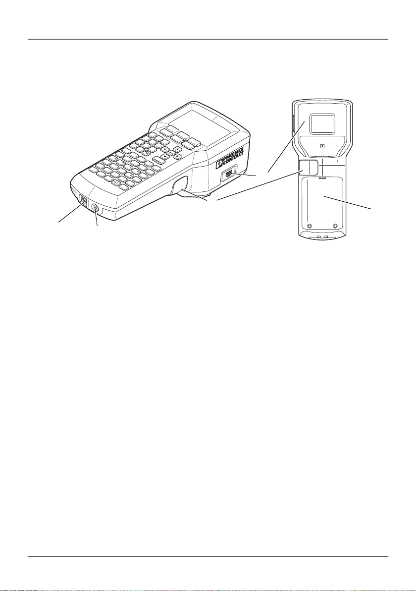
2.2 Overview of the device.............................................................................8
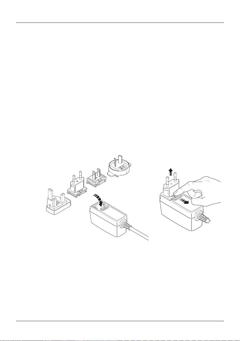
2.3 Connecting the power supply...................................................................9
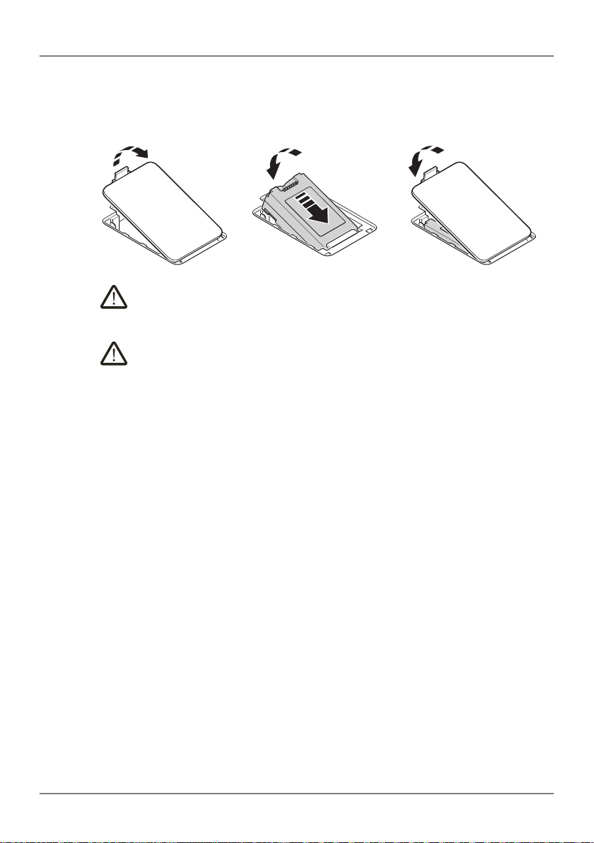
2.4 Inserting the material cartridge...............................................................11
2.5 Switching on the device .........................................................................11
3 Operating elements ...........................................................................12
3.1 Display...................................................................................................14
3.2 Menu......................................................................................................15
4 Creating the marking .........................................................................23
4.1 Creating the marking on the display.......................................................23
4.2 Creating the marking on the PC .............................................................33
4.3 Printing...................................................................................................34
5 Maintenance and troubleshooting .....................................................35
5.1 Cleaning.................................................................................................35
5.2 Troubleshooting.....................................................................................37
5.3 Repairs ..................................................................................................41
5.4 Firmware update....................................................................................41
5.5 Disposal.................................................................................................41
6 Appendix ...........................................................................................42
6.1 Technical data .......................................................................................42
6.2 Ordering data for accessories................................................................43
6.3 Overview of the symbols........................................................................44
6.4 Approvals...............................................................................................47

For your safety
109432_en_00 PHOENIX CONTACT 5 / 50
1 For your safety
Read this user manual carefully and keep it for future reference.
1.1 Identification of warning notes
1.2 Qualification of users
This user manual is aimed at those persons who are familiar with the relevant
safety concepts for handling electrical machines. Only those persons who can
identify hazards may start up, operate, and maintain the device.
This symbol indicates hazards that could lead to personal injury.
There are three signal words indicating the severity of a potential injury.
DANGER
Indicates a hazard with a high risk level. If this hazardous situation is not avoided,
it will result in death or serious injury.
WARNING
Indicates a hazard with a medium risk level. If this hazardous situation is not
avoided, it could result in death or serious injury.
CAUTION
Indicates a hazard with a low risk level. If this hazardous situation is not avoided,
it could result in minor or moderate injury.
This symbol together with the NOTE signal word warns the reader of actions that
might cause property damage or a malfunction.
Here you will find additional information or detailed sources of information.

THERMOMARK GO.K
6 / 50 PHOENIX CONTACT 109432_en_00
1.3 Field of application
The THERMOMARK GO.K is a portable thermal transfer printer for industrial use.
The thermal transfer printer prints self-adhesive and non-adhesive labels and
shrink sleeves for marking electrical components.
The THERMOMARK GO.K uses special material cartridges that contain the mate-
rial as well as the corresponding ink ribbon. Only use material cartridges that are
provided for the THERMOMARK GO.K by Phoenix Contact.
1.4 Safety notes
Hazard to operational safety
Incorrect operation or modifications to the device can endanger your safety or
damage the printer. Do not repair the device yourself. If the device is defective,
please contact Phoenix Contact.
This device is not suitable for use at locations where children might be present.
Explosion hazard, fire hazard, and health hazard if batteries are used incor-
rectly
– Only use dry batteries in a proper condition. Only the associated battery is suit-
able for battery operation (THERMOFOX/ACCU, 0805009).
– Never damage the batteries (e.g., by throwing, pressing on the battery, or us-
ing sharp objects). Never expose the batteries to high levels of heat (e.g.,
caused by fire or sunlight). Never let the batteries come in contact with mois-
ture or salt water.
– Pay attention to the correct polarity when inserting the batteries.
– Only charge the battery in the THERMOMARK GO.K or in the provided char-
ger (THERMOFOX/CHARGER, 0805012). Do not use any other chargers,
e.g., cigarette lighter socket in the car.
– Temperature range when charging the battery: 0°C ... 45°C
– Store the battery separately in a dry and cool place.
– Never expose batteries to an extremely low air pressure.

Starting up the printer
109432_en_00 PHOENIX CONTACT 7 / 50
Damage to the device
– Do not operate the printer near high-voltage lines.
– Only operate the printer in a dry location protected from splash water.
– Protect the printer and printing materials from humidity, moisture, and dirt.
– Only connect the printer to systems that have a protective extra-low voltage.
– To operate the printer on the power grid, only use the supplied wide range
power supply unit (THERMOFOX/ADAPTER, 0805010).
2 Starting up the printer
2.1 Checking the scope of supply
THERMOMARK GO.K
– Printer
– Brief instructions
THERMOMARK GO.K SET
– Printer
– Rechargeable battery (THERMOFOX/ACCU, 0805009)
– Wide range power supply unit with power cable and four adapters for different
sockets (THERMOFOX/ADAPTER, 0805010)
– USB cable
– Two material cartridges
– Vinyl polymer, 18 mm, white (MM-EMLF (EX18)R C1 WH/BK, 0803939)
– Polyamide, 18 mm, white (MM-EMLC (EX18)R C1 WH/BK, 0803936)
Unpacking
• Check the printer for transport damage.

THERMOMARK GO.K
8 / 50 PHOENIX CONTACT 109432_en_00
2.2 Overview of the device
Figure 2-1 Overview
1Socket for USB connection
2Socket for power supply unit
3Lever for cutting continuous material
4Compartment for material cartridge
5Battery compartment
1
File
2
A/
A
3
A
A
/
4
A/A
5
A/A
6
A/A
7
Date
8
Time
9
Te m -
plate
0
A
Del./Back
Clear
Light Feed
Preview
ON/OFF
Menu Print
Copies
A
@
F
(
K
P
$
U
.
F
G
)
L
Q
%
V
,
A/a
M
R
&
W
:
Z
S
X
“
Y
‘
Symbol
Char.
I
\
N
E
*
J
_
O
°
T
#
B
+
C
-
H
/
D
=
12
3
4
5

Starting up the printer
109432_en_00 PHOENIX CONTACT 9 / 50
2.3 Connecting the power supply
The THERMOMARK GO.K can be supplied with power in different ways.
– Batteries (6 x AA alkaline)
– AC wide range power supply unit (THERMOFOX/ADAPTER, 0805010)
– Battery (THERMOFOX/ACCU, 0805009)
If the THERMOMARK GO.K is connected to the power supply via the power supply
unit, the battery in the THERMOMARK GO.K is automatically charged. The battery
can also be charged using an external charger (THERMOFOX/CHARGER,
0805012).
Connecting the power supply unit
The THERMOMARK GO.K is designed for power grids from 100 to 240 V AC.
Only use the supplied wide range power supply unit
(THERMOFOX/ADAPTER, 0805010).
Figure 2-2 Mains connection
• Slightly tilt the relevant adapter and place it onto the front side of the power
supply unit and press the adapter down. To remove the adapter, pull the slider
on the base element in the direction of the cable.
• Plug the connecting cable of the power supply unit into the socket on the print-
er.
• Plug the power supply unit into the socket.
A
B

THERMOMARK GO.K
10 / 50 PHOENIX CONTACT 109432_en_00
Inserting the battery
Figure 2-3 Opening the battery compartment
WARNING: Explosion hazard
Only use batteries of the stated type. Using incorrect types may disable pro-
tective measures.
WARNING: Risk of fire
Only operate the device if the battery cover is closed correctly. Combustible
material close to the battery compartment may ignite.
• To open the battery compartment, push the interlock of the cover in the direc-
tion of the connections.
• Slightly tilting the battery, insert it into the battery compartment making sure of
the correct polarity.
• Press down the battery.
• Close the cover.
ABC

Starting up the printer
109432_en_00 PHOENIX CONTACT 11 / 50
2.4 Inserting the material cartridge
Figure 2-4 Replacing the material cartridge
• Keeping the material cartridge straight, insert it into the compartment from
above so that it engages with a click.
Make sure that the material end is in the output tray.
• To remove the material cartridge, pull it upward while keeping it straight.
NOTE: Damage to the printer and material cartridge
If the printer is not going to be used for a prolonged period of time, remove
the material cartridge from the printer.
2.5 Switching on the device
• Switch on the printer using the green key.
• Press the green key until the display lights up.
ON/OFF
ON/OFF

THERMOMARK GO.K
12 / 50 PHOENIX CONTACT 109432_en_00
3 Operating elements
Figure 3-1 Operating elements
1
File
2
A/A
3
A
A
/
4
A/A
5
A/A
6
A/A
7
Date
8
Time
9
Tem -
plate
0
AB
Del./Back
Clear
Light Feed
Preview
ON/OFF
Menu Print
Copies
A@
F(
K
P$
U.
F
B+
G)
L
Q%
V
,
A/a
C-
H/
M
R&
W:
Z
D=
I\
N
S
X“
E*
J_
O°
T#
Y‘
Symbol
Char.
1
File 2
A/A
3
A
A
/
4
A/A 5
A/A
6
A/A
7
Date 8
Time 9
Te m -
plate
0
AB
Del./Back
Clear
Light Feed
Preview
ON/OFF
Menu Print
Copies
A@
F(
K
P$
U.
F
B+
G)
L
Q%
V
,
A/a
C-
H/
M
R&
W:
Z
D=
I\
N
S
X“
E*
J_
O°
T#
Y‘
Symbol
Char.
Operating elements
Green keys
On/Off switch
Function key, is used to switch to the assignment labeled green when pressing a
key (e.g., @ instead of A).
Black keys Function key pressed
Display lighting –
Material feed –
Preview of the print result –
Call menu
In a value selection: the value is accepted and
you are returned to the input screen
–
Start printing Multiple copies
ON/OFF
F
Light
Feed
Preview
Menu
Print
Copies

Operating elements
109432_en_00 PHOENIX CONTACT 13 / 50
Turquoise keys Function key pressed
Selection of templates –
Changes the text alignment (horizontal/verti-
cal)
–
Confirm entry, new line (up to six lines are
possible)
–
In the menu: back to the previous level
In the input screen: delete previous character
In the input screen: delete entire
contents
Switches between upper case and lower
case letters
–
Space –
Selection of symbols Selection of special characters,
e.g., â, È, ï, Ĉ
Gray keys Function key pressed
Num-
bers
Entry of numbers 0 - 9 1 = File
2 = Font size
3 = Narrow
4 = Bold
5 = Italic
6 = Underline
7 = Date
8 = Time
Letters Letters A - Z Selection of the assignment la-
beled green
Arrow
keys
Line change, navigating in the menu
Operating elements
Te m -
plate
AB
Del./Back
Clear
A/a
Symbol
Char.

THERMOMARK GO.K
14 / 50 PHOENIX CONTACT 109432_en_00
3.1 Display
The first line in the display shows the settings selected.
“F” indicates that the green function key has been pressed. The function key
is used to switch to the assignment labeled green when pressing a key (e.g., @
instead of A).
Indicates whether upper case or lower case letters are being used. Can be
switched using the turquoise key.
Indicates the selected line height in mm. The “A” stands for “auto”. The line height
is adjusted according to the space available.
Can be switched using number key “2” if the function key has been activated si-
multaneously. To set the desired height in mm, press number key “2” several
times (Auto Size, 2 mm ... 22 mm)
Alignment of text
The turquoise key can be used to switch the text alignment. The text align-
ment switches in the following order:
1. horizontal – centered
2. vertical – centered
3. horizontal – right-aligned
4. vertical – right-aligned
5. horizontal – left-aligned
6. vertical – left-aligned
Text format (bold, italic, narrow, underline). Can be switched using the number
keys if the function key has been activated simultaneously.
3 = narrow, 4 = bold, 5 = italic, 6 = underline
Print layouts for specific requirements
– Rows of labels with a fixed width (“Mod”, see Section 4.1.5)
– Cable marking (“CWr”, see Section 4.1.6)
– Cable flags (“CFL”, see Section 4.1.7)
– Insert bar code (“Bar”, see Section 4.1.3)
– Insert number sequence (“Seq”, see Section 4.1.4)
State of the power supply
Examples of the first line in
the display
F
A/a
AB

Operating elements
109432_en_00 PHOENIX CONTACT 15 / 50
3.2 Menu
Use the arrow keys to navigate through the menu. Press the key to select an entry
and to go back.
Changing the language
The menu is set to English by default. To change the language, proceed as follows:
• Press the black key.
• Select “A. Setup”. Press the key.
• Select “1. Language”. Press the key.
• Select a language.
• Press the key to select an entry. Go back with or .
Del./Back
Clear
Menu
Del./Back
Clear
Menu
Table 3-1 Menu
Level 1 Level 2 Level 3 Level 4 Description
1. File 1. Save Save marking
2. Load Load stored marking (1 to 20 files)
3. Print Print stored marking
4. Delete Delete stored marking
2. Font 1. Size Auto Size Font is adjusted according to
space available
2 mm ... 22 mm Font size in mm ABC
2. Style 1. Bold Bold ABC
2. Italic Italic ABC
3. Narrow Narrow
ABC
4. Underline Underline ABC
5. Mirror Mirrored

THERMOMARK GO.K
16 / 50 PHOENIX CONTACT 109432_en_00
3. Symbol Punctuation Punctuation marks ! " #
General symbols General symbols § © ®
Units Units $ £ ¢
Electr. General Electrical symbols 86
Electr. Comp. Electrical components
Home Electrics Home electrics
Safety Signs Safety symbols
Superscript Superscript characters - +
Subscript Subscript characters - +
Arrows Arrows
Greek Upper Case Greek upper case letters ΑΒΓΔ
Greek Lower Case Greek lower case letters αβγδ
Mathematical Character Mathematical symbols
4.
Orienta-
tion
1. Horizontal Horizontal text alignment ABC
2. Vertical Vertical text alignment
ABC
5. Align-
ment
1. Left Left-aligned text ABC
2. Center Centered text ABC
3. Right Right-aligned text ABC
Table 3-1 Menu [...]
Level 1 Level 2 Level 3 Level 4 Description

Operating elements
109432_en_00 PHOENIX CONTACT 17 / 50
6. Frame 1. No Frame No frame
2. Dotted Frame, dashed line
3. Thin Frame, thin line
4. Medium Frame, standard line
5. Thick Frame, thick line
7. Margin 1. Least
Width from right and left
margin
1 mm
2. Small 2 mm
3. Medium 5 mm
4. Large 10 mm
5. Text-equal All margins are adjusted evenly ac-
cording to the text size
6. User Set Set fixed width from right and left
margin (1 mm ... 400 mm)
8. Length 1. Auto Length The length of the printed text de-
pends on the marking and the set
margin
2. User Set Set fixed length (4 mm ... 400 mm)
Table 3-1 Menu [...]
Level 1 Level 2 Level 3 Level 4 Description

THERMOMARK GO.K
18 / 50 PHOENIX CONTACT 109432_en_00
9. Template 1. Normal Empty template
2. Barcode Barcode
Type
Code 39,
Code 128,
Interleaved
2/5, Cod-
abar, EAN-
8, EAN-13,
EAN-128,
UPC-A
You can implement Micro QR
Code, DataMatrix, and PDF417 via
PROJECT complete
Width Small, Me-
dium,
Large
Bar code width
Display
Text
No, Yes The text encrypted in the bar code
is displayed below the bar code
Check
Code
No, Yes A check digit is added, if required
3. Sequence Auto
Length
StaVal Start value of a sequence of num-
bers (2 = 2, 3 ...)
IncVal Increment of a sequence of num-
bers (2 = 2, 4, 6...)
EndVal End value of a sequence of num-
bers (5 = ... 3, 4, 5)
SepLine Separator line
Orient. Text alignment of the module: hori-
zontal or vertical
Prefix Prefix of a sequence of numbers
(-X = -X1, -X2...)
Suffix Suffix of a sequence of numbers
(-X = 1-X, 2-X...)
Copies Repetitions (2 = 1, 1, 2, 2...)
Table 3-1 Menu [...]
Level 1 Level 2 Level 3 Level 4 Description

Operating elements
109432_en_00 PHOENIX CONTACT 19 / 50
9. Template 3. Sequence Pitch StaVal Start value of a sequence of num-
bers (2 = 2, 3 ...)
IncVal Increment of a sequence of num-
bers (2 = 2, 4, 6...)
EndVal End value of a sequence of num-
bers (5 = ... 3, 4, 5)
Pitch Width for each module, pitch
SepLine Separator line
Orient. Text alignment of the module: hori-
zontal or vertical
Prefix Prefix of a sequence of numbers
(-X = -X1, -X2...)
Suffix Suffix of a sequence of numbers
(-X = 1-X, 2-X...)
Copies Repetitions (2 = 1, 1, 2, 2...)
4. Module Total Number of modules,
[1 ... 64] one line, [1 ... 32] two lines
Pitch Width for each module, pitch
Factor Factor for the width
SepLine Dotted,
Thin, Me-
dium,
Thick, Off
Separator line
Orient. Hor., Ver. Text alignment of the module: hori-
zontal or vertical
5. Cable Wrap
Horizontal
Auto
Length
Length of the cable marking is ad-
justed according to space avail-
able
User Set
User-defined length of the cable
marking (4 mm ... 400 mm)
Vertical Diameter Diameter of the cable
(4 mm ... 100 mm)
Cross
section
Cross-section of the cable
(0.25 mm²/AWG 22 ...
50 mm²/AWG 0)
Table 3-1 Menu [...]
Level 1 Level 2 Level 3 Level 4 Description

THERMOMARK GO.K
20 / 50 PHOENIX CONTACT 109432_en_00
9. Template 6. Cable Flag Orient. Hor., Ver. Text alignment of the cable flag
Wrap
Length
Diameter Diameter of the cable
(4 mm ... 100 mm)
Cross
section
Cross-section of the cable
(0.25 mm²/AWG 22 ...
50 mm²/AWG 0)
Flag
Length
Auto
Length,
User Set
Length of the cable flag: automatic
or user-defined 4 mm ... 400 mm
Center
Line
Off, Dotted,
Thin, Me-
dium, Thick
Center line as folding guide
A. Setup 1. Language English
German
French
Spanish
Italian
Czech
Dutch
Hungarian
Polish
Portuguese
Turkish
Korean
Japanese
Languages for the menu
Table 3-1 Menu [...]
Level 1 Level 2 Level 3 Level 4 Description
This manual suits for next models
3
Table of contents
Other Phoenix Contact Printer manuals

Phoenix Contact
Phoenix Contact THERMOMARK ROLL User manual

Phoenix Contact
Phoenix Contact BLUEMARK ID User manual

Phoenix Contact
Phoenix Contact THERMOMARK PRIME User manual

Phoenix Contact
Phoenix Contact Clipline Thermomark S1 Quick start guide

Phoenix Contact
Phoenix Contact THERMOMARK ROLL 2.0 User manual

Phoenix Contact
Phoenix Contact UM IA THERMOMARK X1.1 User manual

Phoenix Contact
Phoenix Contact THERMOMARK ROLLMASTER 600 User manual

Phoenix Contact
Phoenix Contact THERMOMARK CARD 2.0 User manual

Phoenix Contact
Phoenix Contact THERMOFOX User manual

Phoenix Contact
Phoenix Contact THERMOMARK CARD Series User manual