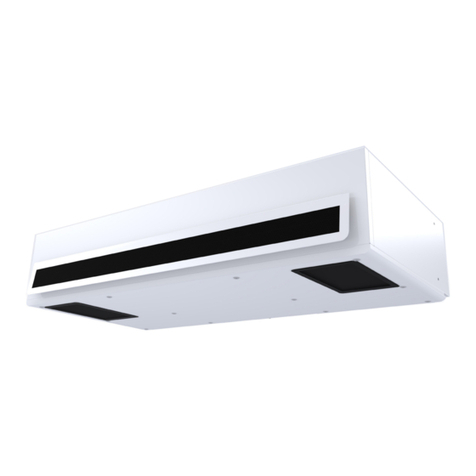
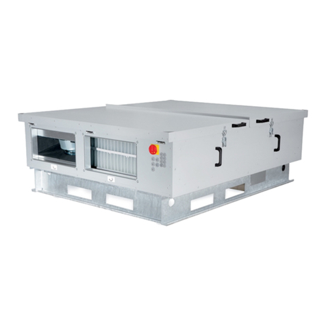
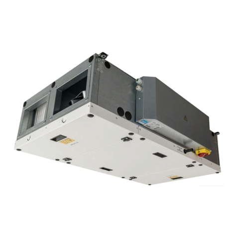
2VV Essensse Neo VCES2-B Series User manual

ESSENSSE NEO
VCES2-B-xx,
VCES2-C-xx
EN INSTALLATION
4-118-0246
P01-0215-0517-00

2
1. BEFORE YOU BEGIN
Before installing, read carefully the section Safe use of the air curtains, where you will nd all the instructions
for the safe and proper use of the product.
Symbol Meaning
CAUTION!
PLEASE NOTE!
you will need
TECHNICAL INFORMATION
Warning or Caution
Important instructions
Practical tips and information
Detailed technical information
Reference to another part of the
manual
This manual includes important instructions for the appropriate installation of the air curtains. Before installing,
read carefully all the following instructions and observe them. The manufacturer reserves the right to change, including the
technical documentation, without prior notice. Keep the manual for future use. The instructions herein are part of the product
Declaration of conformity
Details can be found at www.2VV.cz

3
PLEASE NOTE
• If the unit was transported in temperatures lower than 0°C,
after unpacking, leave it in operational conditions for at
least two hours without activating in order to compensate
the inner temperature.
2. UNPACKING
3. MAIN COMPONENTS
2.1 CONTROL DE DELIVERY
PLEASE NOTE
Check the product for damages immediately after delivery. In
case of damage to the packaging, contact the carrier. Claims
not led in due time will be disregarded.
• Check that it corresponds to the type of product ordered.
In case of discrepancy, do not unpack the product and con-
tact the vendor.
• After unpacking, check that the product and all the other
components are in good order. In case of doubt, contact
the vendor.
• Do not install a damaged unit!
• If you will not unpack the product immediately after delive-
ry, store it indoors, in a dry place with ambient temperatu-
res between +5 °C and +40 °C.
2.2 CONTENTS
+5 oC
+40 oC
All the packaging material is environ-
mentally friendly and can be reused or
recycled. Contribute actively to the pro-
tection of the environment and ensure
the proper disposal or recycling of the
packaging materials.
2x
1x
1x
4x M6x20
1
2
3
4
5
6
71
1
23
4
5
7
6
6
Mounting brackets (2pcs)
Curtain body
Area to connect the control module
Suction cover
Connection of water exchanger (only water model)
Side cover
erminal box for main power connection.

4
4. DIMENSIONS
Type Weight
(kg) Type Weight
(kg)
VCES2B-100-E 25,5 VCES2C-100-E 27,3
VCES2B-150-E 32,6 VCES2C-150-E 37,4
VCES2B-200-E 39,8 VCES2C-200-E 47,7
VCES2B-250-E 46,9 VCES2C-250-E 55,8
VCES2B-100-V 26,1 VCES2C-100-V 27,6
VCES2B-150-V 32,9 VCES2C-150-V 39,3
VCES2B-200-V 40,1 VCES2C-200-V 47,6
VCES2B-250-V 47,4 VCES2C-250-V 55,3
VCES2B-100-S 24,8 VCES2C-100-S 26,3
VCES2B-150-S 31,3 VCES2C-150-S 35,7
VCES2B-200-S 38,3 VCES2C-200-S 45,8
VCES2B-250-S 45,1 VCES2C-250-S 53,1
A
I
8
H
G
E
F
B
C
15
15
J
D
TYPE
A B C D E F G H I J
(mm) (mm) (mm) (mm) (mm) (mm) (mm) (mm) (mm) (mm)
VCES2B-100 913 1190 377 252 51 111 90 211 67 3/4"
VCES2C-100 913 1190 377 252 51 111 90 211 67 3/4"
VCES2B-150 1321 1600 377 252 51 111 90 211 67 3/4"
VCES2C-150 1321 1600 377 252 51 111 90 211 67 3/4"
VCES2B-200 1822 2100 377 252 51 111 90 211 67 3/4"
VCES2C-200 1822 2100 377 252 51 111 90 211 67 3/4"
VCES2B-250 2232 2510 377 252 51 111 90 211 67 3/4"
VCES2C-250 2232 2510 377 252 51 111 90 211 67 3/4"

5
5. TECHNICAL PARAMETERS
Type
Heater output
[kW]* Total consumption
[A]
Motor Supply frequency
[Hz]
Power (W) Current
(A)
Tension
(V)
1st step 2nd step
VCES2B-100-E0
3,2 4,7
13,8 161 0,7
230
50/60
VCES2B-150-E0
3,8 7,5
11,9 230 1 50/60
VCES2B-200-E0
4,8 9,5
15,4 299 1,3 50/60
VCES2B-250-E0
6,9 12,2
19,4 370 1,6 50/60
VCES2B-100-E1
3,2 6,3
13,8 161 0,7 50/60
VCES2B-150-E1
5 10
21,8 230 1 50/60
VCES2B-200-E1
6,3 12,6
27,5 299 1,3 50/60
VCES2B-250-E1
8,2 16,3
26,2 370 1,6 50/60
VCES2B-100-E2
4,7 9,5
14,5 161 0,7 50/60
VCES2B-150-E2
7,5 15
22,8 230 1 50/60
VCES2B-200-E2
9,5 19
29,1 299 1,3 50/60
VCES2B-250-E2
12,2 24,5
37,1 370 1,6 50/60
VCES2B-100-V 16,9 0,7 161 0,7 50/60
VCES2B-150-V 24,7 1 230 1 50/60
VCES2B-200-V 35,7 1,3 299 1,3 50/60
VCES2B-250-V 43,3 1,6 370 1,6 50/60
VCES2B-100-S - - 0,7 161 0,7 50/60
VCES2B-150-S - - 1 230 1 50/60
VCES2B-200-S - - 1,3 299 1,3 50/60
VCES2B-250-S - - 1,6 370 1,6 50/60
VCES2C-100-E1 5 9,9 15,4 370 1,6
230
50/60
VCES2C-150-E1 7,9 15,2 23,8 460 2 50/60
VCES2C-200-E1 10,2 19,1 30,7 690 3 50/60
VCES2C-250-E1 12,9 25,1 38,9 740 3,2 50/60
VCES2C-100-V 22,4 1,6 370 1,6 50/60
VCES2C-150-V 31,8 2 460 2 50/60
VCES2C-200-V 44,4 3 690 3 50/60
VCES2C-250-V 53,7 3,2 740 3,2 50/60
VCES2C-100-S - - 1,6 370 1,6 50/60
VCES2C-150-S - - 2 460 2 50/60
VCES2C-200-S - - 3 690 3 50/60
VCES2C-250-S - - 3,2 740 3,2 50/60
* Intake air temperature +18°C, at maximum heater output and fan speed.
The other technical parameters can be found in the corresponding technical sheet of the product

6
6. INSTALLATION
6.1 OPERATIONAL CONDITIONS:
The air curtain is designed to be used in an indoor, dry envi-
ronment, with ambient temperatures between 5°C to +40°C,
a maximum relative humidity of 80%, and to transport air free
of coarse dust, grease, chemical fumes and other contamina-
tion. The electrical protection is IP 20 (against particles larger
than 12.5 mm, not protected against water).
Curtains with electric heater are tted with an operational
thermostat with automatic reset (located on each heater) and
an emergency thermostat with manual reset.
The water exchangers are designed for a maximum water
temperature of +100°C and maximum pressure of 1.6 MPa.
6.2 INSTALLATION CONDITIONS
The installation and assembly of the unit may be carried out
only by a suitably qualied person who has the adequate
tools!
2 mounting brackets and 4 bolts are supplied with the prod-
uct as standard.
If the unit is to be mounted on threaded rods, they have to be
ordered separately. The following rules should be observed
for the proper function of the unit.
PLEASE NOTE
• minimum clearances must be observed (see g. clearanc-
es) with respect to the ammability of materials.
• the clearances with respect to the ammability of materials
are determined by the architect with regards to the regula-
tions applicable at the place of installation
• the unit may be installed only in horizontal position
• there must be at least 200 mm of free space in front of the
suction cover for the proper functioning of the unit
• the exhaust should be located as near as possible to the
door or the curtain opening
• the curtain should extend beyond both sides of the open-
ing by at least 100 mm
• if the curtain is to be installed above a door, place it as near
as possible to the upper border of the door. See that the in-
take and exhaust are not blocked and that the air can ow
freely, see g.
min. 200 mm
min. 100 mm
min. 50 mm*
min. 200 mm
min. 100 mm
min. 50 mm*
min. 100mm
min. 200mm
If there is a window above the door or another material pre-
venting the installation on the brackets, the unit may be
hanged from the ceiling with threaded rods, directly onto
dowels (see below).
Installation with mounting brackets
YOU WILL NEED
4x dowels (not included)
4x bolts (not included)
Measure the holes on the wall according to the dimension
chart (see “Dimensions”) (observe the installation rules) Do
not forget to choose whether the unit will be installed ac-
cording to A or B and to set the height of the opening accord-
ing to that! Insert back in the opening in the curtain (and
only partially in the curtain) the screws that held the brackets
and hang the curtain from them. Check that the curtain is
fastened properly to prevent it falling
6.3 SUSPENSION:
7
6. INSTALLATION
Before installing, check that the ceiling can bear the weight of
the unit. Install according to the following gures.
1. Fastening to the ceiling
2. Fastening to the curtain
10mm
30mm
4x
30mm
10mm
hanging from threaded rods
Installation with threaded rods
YOU WILL NEED
4 6mm anchors (not included)
4 M6 threaded rods (not included)
8 M6 nuts (not included)
M10 spanner (not included)

8
6. INSTALLATION
6.4.2 Installing the control module
(Not included)
1) insert the module into the unit
12 3
4
5
3mm
6
Siko pliers are not included
CAUTION!
Tighten the terminal box with the help of the tool
Tensioning the terminal block using the siko tongs:
6.4 Installing the control module (detailed
instructions can be found in the respective
manual)
The following procedure requires the removal of the suction
cover
6.4.1. remove the design sideboard fas-
tened with two M5 screws on the side of
the motor
3mm

9
6.5 Connecting the water heater
(only for the curtain with LPHW )
)
• exible hoses are recommended to connect the water
heater
• the connection and pressure tests of the heater must be
carried out by a person with qualications in plumbing and
in compliance with the applicable regulations
• the diameters of the pipes to connect the water heater are
listed in the section DIMENSIONS
• the heater is designed for water with a maximum pressure
of 1.6 MPa and a maximum temperature of +100°C.
When connecting the heater, hold the outlet with pliers
to prevent damages (see gure)
PLEASE NOTE
• connect the pipes in the countercurrent connection, the
hot water connection and the return heating water are
shown in the gure above
• it is advisable to install a shut-o valve at the inlet and the
outlet of the heater to interrupt the water supply
2) Insert and fasten the regulator’s terminal box to the cur-
tain’s terminal box with the supplied tool or with Siko pliers.
3) Tighten all the screws of the module.
4) Fasten the regulator with a screw, see gure below
TECHNICAL INFORMATION
The tool to install the module is supplied with the module.
6.4.3 Connecting the supply cables
• The power cable may be connected to the main terminal
box located on the upper part of the unit only after hav-
ing installed the control module (see gure below).
• Pull the regulator’s communication cable.
• Pull the cables to the accessories, if applicable
CAUTION!
The supply must be determined by the relevant designer,
it must comply with the applicable regulations and take
into account the power an installation parameters of the
air curtain
6. INSTALLATION

10
CAUTION!
Before starting up the unit check that:
• No tools or other objects that may damage the unit have
been left inside.
• The power and heating water supply are well connected.
• The unit is properly covered.
• The control panel is properly connected
During the commissioning, check the proper function of the
unit (fans, heating). Check the other possible settings and
functions according to the user manual of each regulator
7. COMMISSIONING
7.1 SETTING THE DIRECTION OF THE EX-
HAUST AIR
CAUTION!
Deect the exhaust in the desired direction during the instal-
lation of the unit The exhausts of the Essensse air curtain can
blow air at a maximum angle of 15°
15°

11
8. CLEANING AND MAINTENANCE
8.1 CLEANING
ATTENTION!
Before carrying out any work inside the air curtain, the main power input must be disconnected. The air curtain must be
allowed to cool down!
• It is forbidden to use compressed air, aggressive chemicals, solvents or water for cleaning.
• Clean using a damp cloth, ne brush or vacuum cleaner.
• Clean the surface of the air curtain including the suction inlet part.
• Clean as necessary, it is recommended that cleaning should be performed at least once every 3 months.
• Adhere to workplace safety and use protective aids.
9. SERVIS
9.1 WHEN YOU AREN‘T ABLE TO REMOVE DEFECT BY YOURSELF
If you are unable to resolve the problem, contact the supplier.
For the fast removal of defects please provide the following information:
- product reference number
- serial number
- running time
- used accessories
- installation location
- installation condition (including electrical)
- detailed description of the problem and the steps that you have taken for its removal
Warranty and post-warranty service is performed by the manufacturer, supplier or authorized service organizati-
on. When ordering service intervention it is necessary to describe the defect, product type designation indicated
on its label, and the location of installation.
9.2 PUTTING THE PRODUCT OUT OF OPERATION - DISPOSAL
Before disposing of the product, make the product unusable. Even old products contain raw materials that can be reused. Take
them to a collection point of secondary raw materials.
The product is good to dispose at the place, which is specialized for it, and thus it will be possible to recycle materials. Store unusa-
ble parts of the product at a controlled dump.
When disposing of materials, it is necessary to observe the relevant national regulations on waste disposal.

12
10. WIRING DIAGRAM
VSES2B100-E1AC-ZP-xxx
VSES2B100-V1,S0AC-ZP-xxx

13
VSES2B100-E1AC-ZP-xxx
VSES2B100-V1,S0AC-ZP-xxx
VSES2B150-E1AC-ZP-xxx
10. WIRING DIAGRAMS
VSES2B150-V1,S0AC-ZP-xxx

14
VSES2B200-E1AC-ZP-xxx
VSES2B200-V1,S0AC-ZP-xxx
10. WIRING DIAGRAM

15
VSES2B200-E1AC-ZP-xxx
VSES2B200-V1,S0AC-ZP-xxx
VSES2B250-E1AC-ZP-xxx
VSES2B250-V1,S0AC-ZP-xxx
10. WIRING DIAGRAMS

16
VSES2C100-E1AC-ZP-xxx
VSES2C100-V1,S0AC-ZP-xxx
10. WIRING DIAGRAM

17
VSES2C100-E1AC-ZP-xxx
VSES2C100-V1,S0AC-ZP-xxx
VSES2C150-E1AC-ZP-xxx
VSES2C150-V1,S0AC-ZP-xxx
10. WIRING DIAGRAMS

18
VSES2C200-E1AC-ZP-xxx
VSES2C200-V1,S0AC-ZP-xxx
10. WIRING DIAGRAM

19
VSES2C200-E1AC-ZP-xxx
VSES2C200-V1,S0AC-ZP-xxx
VSES2C250-E1AC-ZP-xxx
VSES2C250-V1,S0AC-ZP-xxx
10. WIRING DIAGRAMS

20
After installing the air curtain, read carefully the Manual for the appropriate regulator. In case of any doubt or query, do not
hesitate to contact our sales or technical support departments.
CONTACT
Address:
2VV, s.r.o.,
Poděbradská 289,
530 09 Pardubice,
Česká republika
Internet:
http://www.2vv.cz/
11. CONCLUSION
This manual suits for next models
25
Table of contents
Other 2VV Fan manuals

2VV
2VV VENUS READY Owner's manual

2VV
2VV ALFA EC Series Installation instructions

2VV
2VV Whisper Air HRWA1-040 Series Guide

2VV
2VV HRFL2 User manual

2VV
2VV ALFA 85 User manual

2VV
2VV FINESSE EC User manual

2VV
2VV ALFA 85 User manual

2VV
2VV ALFA 95 II horizontal User manual

2VV
2VV DAPHNE User manual

2VV
2VV ALFA 85 Owner's manual
Popular Fan manuals by other brands

AERMEC
AERMEC Omnia ULI 16 C Use and installation manual

CFM
CFM 165834 Brochure & specs

Fanimation
Fanimation FP7948 Series owner's manual

BVN
BVN BRF-V User manual & certificate of warranty

Olimpia splendid
Olimpia splendid Bubble Instructions for installation, use and maintenance

Helios
Helios MegaBox MB Series Operating and installation instructions