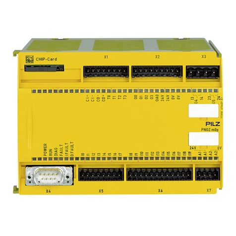
Pilz PNOZ m ES ETH User manual

PNOZmESETH
OperatingManual1002700EN04
ConfigurableControlSystemPNOZmulti

Preface
Thisdocumentisatranslationoftheoriginaldocument.
AllrightstothisdocumentationarereservedbyPilzGmbH&Co.KG.Copiesmaybemade
forinternalpurposes.Suggestionsandcommentsforimprovingthisdocumentationwillbe
gratefullyreceived.
Pilz®,PIT®,PMI®,PNOZ®,Primo®,PSEN®,PSS®,PVIS®,SafetyBUSp®,
SafetyEYE®,SafetyNETp®,thespiritofsafety®areregisteredandprotectedtrademarks
ofPilzGmbH&Co.KGinsomecountries.
SDmeansSecureDigital

Content
OperatingManualPNOZmESETH
1002700EN04 3
Section1 Introduction 4
1.1 Validityofdocumentation 4
1.2 Retainingthedocumentation 4
1.3 Definitionofsymbols 4
Section2 Overview 6
2.1 Scopeofdelivery 6
2.2 Unitfeatures 6
2.3 Frontview 7
Section3 Safety 8
3.1 Intendeduse 8
3.2 Systemrequirements 8
3.3 Safetyregulations 8
3.3.1 Useofqualifiedpersonnel 8
3.3.2 Warrantyandliability 9
3.3.3 Disposal 9
3.3.4 Foryoursafety 9
Section4 Functiondescription 10
4.1 Unitproperties 10
4.2 Blockdiagram 10
Section5 Installation 11
5.1 Generalinstallationguidelines 11
5.2 Dimensions 11
5.3 Connectingthebaseunitandexpansionmodules 11
Section6 Commissioning 13
6.1 Generalwiringguidelines 13
6.2 Preparingforoperation 13
6.3 DownloadmodifiedprojecttothePNOZmultisafetysystem 13
6.4 Ethernetinterfaces 13
6.4.1 RJ45interfaces("Ethernet") 13
6.4.2 Requirementsoftheconnectioncableandconnector 14
6.4.3 Interfaceconfiguration 14
6.4.4 RJ45connectioncable 15
6.4.5 Processdataexchange 16
Section7 Operation 17
7.1 Messages 17
7.2 ResetEthernetconnectionsettings 18
Section8 Tecnicaldetails 19
Section9 Orderreference 21
9.1 Module 21
9.2 Accessories 21

Introduction
OperatingManualPNOZmESETH
1002700EN04 4
1 Introduction
1.1 Validityofdocumentation
ThisdocumentationisvalidfortheproductPNOZmESETH.Itisvaliduntilnewdocument
ationispublished.
Thisoperatingmanualexplainsthefunctionandoperation,describestheinstallationand
providesguidelinesonhowtoconnecttheproduct.
1.2 Retainingthedocumentation
Thisdocumentationisintendedforinstructionandshouldberetainedforfuturereference.
1.3 Definitionofsymbols
Informationthatisparticularlyimportantisidentifiedasfollows:
DANGER!
Thiswarningmustbeheeded!Itwarnsofahazardoussituationthatposes
animmediatethreatofseriousinjuryanddeathandindicatespreventive
measuresthatcanbetaken.
WARNING!
Thiswarningmustbeheeded!Itwarnsofahazardoussituationthatcould
leadtoseriousinjuryanddeathandindicatespreventivemeasuresthatcan
betaken.
CAUTION!
Thisreferstoahazardthatcanleadtoalessseriousorminorinjuryplus
materialdamage,andalsoprovidesinformationonpreventivemeasures
thatcanbetaken.
NOTICE
Thisdescribesasituationinwhichtheproductordevicescouldbedam
agedandalsoprovidesinformationonpreventivemeasuresthatcanbe
taken.Italsohighlightsareaswithinthetextthatareofparticularimport
ance.

Introduction
OperatingManualPNOZmESETH
1002700EN04 5
INFORMATION
Thisgivesadviceonapplicationsandprovidesinformationonspecialfea
tures.

Overview
OperatingManualPNOZmESETH
1002700EN04 6
2 Overview
2.1 Scopeofdelivery
}ExpansionmodulePNOZmESETH
}Jumper779260
2.2 Unitfeatures
UsingtheproductPNOZmESETH:
Communicationmoduleforconnectiontoabaseunitfromtheconfigurablecontrolsystem
PNOZmulti2.
Theproducthasthefollowingfeatures:
}CanbeconfiguredinthePNOZmultiConfigurator
}2Ethernetinterfaces
}Statusindicatorsforsupplyvoltage,communicationanderrors
}Max.1communicationmodulecanbeconnectedtotheleftofthebaseunitPNOZmulti
2
}Pleaserefertothedocument"PNOZmultiSystemExpansion"forthePNOZmultibase
unitsthatcanbeconnected

Overview
OperatingManualPNOZmESETH
1002700EN04 7
2.3 Frontview
Legend:
}X1,X2:
Ethernetinterfaces
}LEDs:
– Power
– DHCP
– L/A1(Link/‘Act1)
– L/A2(Link/Act2)

Safety
OperatingManualPNOZmESETH
1002700EN04 8
3 Safety
3.1 Intendeduse
Theexpansionmodule PNOZmESETHisusedforcommunicationoftheconfigurablecon
trolsystemPNOZmulti2viaEthernet.
Theexpansionmodulemayonlybeconnectedtoabaseunitfromtheconfigurablecontrol
systemPNOZmulti2(pleaserefertothedocument"PNOZmultiSystemExpansion"forde
tailsofthebaseunitsthatcanbeconnected).
TheconfigurablecontrolsystemPNOZmulti2isusedforthesafetyrelatedinterruptionof
safetycircuitsandisdesignedforusein:
}ESTOPequipment
}SafetycircuitsinaccordancewithVDE0113Part1andEN602041
Theexpansionmodulemaynotbeusedforsafetyrelatedfunctions.
IntendeduseincludesmakingtheelectricalinstallationEMCcompliant.Theproductisde
signedforuseinanindustrialenvironment.Itisnotsuitableforuseinadomesticenviron
ment,asthiscanleadtointerference.
Thefollowingisdeemedimproperuseinparticular:
}Anycomponent,technicalorelectricalmodificationtotheproduct
}Useoftheproductoutsidetheareasdescribedinthismanual
}Useoftheproductoutsidethetechnicaldetails(seechapterentitled“TechnicalDe
tails”)
3.2 Systemrequirements
Pleaserefertothe"ProductModifications"documentinthe"Versionoverview"sectionfor
detailsofwhichversionsofthebaseunitandPNOZmultiConfiguratorcanbeusedforthis
product.
3.3 Safetyregulations
3.3.1 Useofqualifiedpersonnel
Theproductsmayonlybeassembled,installed,programmed,commissioned,operated,
maintainedanddecommissionedbycompetentpersons.
Acompetentpersonissomeonewho,becauseoftheirtraining,experienceandcurrentpro
fessionalactivity,hasthespecialistknowledgerequiredtotest,assessandoperatethe
workequipment,devices,systems,plantandmachineryinaccordancewiththegeneral
standardsandguidelinesforsafetytechnology.
Itisthecompany’sresponsibilityonlytoemploypersonnelwho:
}Arefamiliarwiththebasicregulationsconcerninghealthandsafety/accidentpreven
tion
}Havereadandunderstoodtheinformationprovidedinthisdescriptionunder"Safety"
}Andhaveagoodknowledgeofthegenericandspecialiststandardsapplicabletothe
specificapplication.

Safety
OperatingManualPNOZmESETH
1002700EN04 9
3.3.2 Warrantyandliability
Allclaimstowarrantyandliabilitywillberenderedinvalidif
}Theproductwasusedcontrarytothepurposeforwhichitisintended
}Damagecanbeattributedtonothavingfollowedtheguidelinesinthemanual
}Operatingpersonnelarenotsuitablyqualified
}Anytypeofmodificationhasbeenmade(e.g.exchangingcomponentsonthePCB
boards,solderingworketc.).
3.3.3 Disposal
}Insafetyrelatedapplications,pleasecomplywiththemissiontimetMinthesafetyre
latedcharacteristicdata.
}Whendecommissioning,pleasecomplywithlocalregulationsregardingthedisposalof
electronicdevices(e.g.ElectricalandElectronicEquipmentAct).
3.3.4 Foryoursafety
Theunitmeetsallnecessaryconditionsforsafeoperation.However,youshouldalwaysen
surethatthefollowingsafetyrequirementsaremet:
}Thisoperatingmanualonlydescribesthebasicfunctionsoftheunit.Informationonthe
advancedfunctionscanbefoundintheonlinehelpforthePNOZmultiConfiguratorand
inthePNOZmultitechnicalcatalogue.Onlyusethesefunctionsafteryouhavereadand
understoodthedocumentation.Allnecessarydocumentationcanbefoundonthe
PNOZmultiConfiguratorCD.
}Donotopenthehousingormakeanyunauthorisedmodifications.
}Pleasemakesureyoushutdownthesupplyvoltagewhenperformingmaintenance
work(e.g.exchangingcontactors).

Functiondescription
OperatingManualPNOZmESETH
1002700EN04 10
4 Functiondescription
4.1 Unitproperties
TheproductPNOZmESETHhastwoEthernetinterfacesto
}Downloadtheproject
}Readthediagnosticdata
}Setvirtualinputsforstandardfunctions
}Readvirtualoutputsforstandardfunctions
viaEthernet(TCP/IP,Modbus/TCP).
InformationondiagnosticsviatheEthernetinterfacescanbefoundinthedocumententitled
"PNOZmulti2communicationinterfaces".
TheconnectiontoEthernetismadeviathetwo8pinRJ45sockets.
TheEthernetinterfaceisconfiguredinthePNOZmultiConfiguratorandisdescribedinthe
onlinehelpforthePNOZmultiConfigurator.
4.2 Blockdiagram
Base unit
Ethernet

Installation
OperatingManualPNOZmESETH
1002700EN04 11
5 Installation
5.1 Generalinstallationguidelines
}Theunitshouldbeinstalledinasinglemountingareawithaprotectiontypeofatleast
IP54.
}Fitthesafetysystemtoahorizontalmountingrail.Theventingslotsmustfaceupwards
anddownwards.Othermountingpositionscoulddestroythesafetysystem.
}Usethelockingslideontherearoftheunittoattachittoamountingrail.
}Inenvironmentsexposedtoheavyvibration,theunitshouldbesecuredusingafixing
element(e.g.retainingbracketorendangle).
}Openthelockingslidebeforeliftingtheunitfromthemountingrail.
}TocomplywithEMCrequirements,themountingrailmusthavealowimpedancecon
nectiontothecontrolcabinethousing.
}TheambienttemperatureofthePNOZmultiunitsinthecontrolcabinetmustnotexceed
thefigurestatedinthetechnicaldetails,otherwiseairconditioningwillberequired.
CAUTION!
Damageduetoelectrostaticdischarge!
Electrostaticdischargecandamagecomponents.Ensureagainstdischarge
beforetouchingtheproduct,e.g.bytouchinganearthed,conductivesur
faceorbywearinganearthedarmband.
5.2 Dimensions
101,4 (4,11“)
111,0 (4,37“)
22,5
(0,88“)
5.3 Connectingthebaseunitandexpansionmodules
Connectthebaseunitandtheexpansionmoduleasdescribedintheoperatinginstructions
forthebaseunits.
}InstalltheexpansionmoduleinthepositioninwhichitisconfiguredinthePNOZmulti
Configurator.

Installation
OperatingManualPNOZmESETH
1002700EN04 12
}Connectthebaseunitandexpansionmodulesusingtheyellow/blackjumper.
}Connecttheblack/yellowterminatortotheexpansionmodule.

Commissioning
OperatingManualPNOZmESETH
1002700EN04 13
6 Commissioning
6.1 Generalwiringguidelines
ThewiringisdefinedinthecircuitdiagramofthePNOZmultiConfigurator.
Pleasenote:
}Informationgiveninthe"Technicaldetails"mustbefollowed.
}Usecopperwirethatcanwithstand75°C.
6.2 Preparingforoperation
DetectionandactivationoftheEthernetinterface,dependingontheUSBinterfaceonthe
baseunit:
}USBinterfaceonthebaseunitnotconnected
IftheUSBinterfaceonthebaseunitisnotconnected,theEthernetinterfacewillbede
tectedandactivatedbythebaseunitassoonasthecommunicationmodulehasbeen
connectedtothebaseunit.
}USBinterfaceonthebaseunitconnected
IftheUSBinterfaceonthebaseunitisalreadyconnected,the"Ethernet"interfacewill
firstneedtobeselectedonthebaseunitdisplaytoenabletheEthernetinterfaceonthe
baseunittobedetectedandactivated(seeoperatingmanualforthebaseunitforde
tailsofthesetting).
6.3 DownloadmodifiedprojecttothePNOZmultisafetysystem
Assoonasanadditionalexpansionmodulehasbeenconnectedtothesystem,theproject
mustbeamendedusingthePNOZmultiConfigurator.Proceedasdescribedintheoperat
inginstructionsforthebaseunit.
NOTICE
Forthecommissioningandaftereveryprogramchange,youmustcheck
whetherthesafetydevicesarefunctioningcorrectly.
6.4 Ethernetinterfaces
6.4.1 RJ45interfaces("Ethernet")
TwofreeswitchportsareprovidedasEthernetinterfacesviaaninternalautosensing
switch.Theautosensingswitchautomaticallydetectswhetherdatatransferisoccurringat
10Mbit/sor100Mbit/s.

Commissioning
OperatingManualPNOZmESETH
1002700EN04 14
INFORMATION
Theconnectedsubscribersmustsupporttheautosensing/autonegotiation
function.Ifnot,thecommunicationpartnermustbesetpermanentlyto"10
Mbit/s,halfduplex".
Theswitch'sautomaticcrossoverfunctionmeansthereisnoneedtodistinguishonthe
connectioncablebetweenpatchcable(uncrosseddatalineconnection)andcrossover
cable(crossoverdatalineconnection).Theswitchautomaticallycreatesthecorrectdata
lineconnectioninternally.Patchcablecanthereforebeusedastheconnectioncablefor
enddevicesaswellascascading.
BothEthernetinterfacesuseRJ45technology.
6.4.2 Requirementsoftheconnectioncableandconnector
Thefollowingminimumrequirementsmustbemet:
}Ethernetstandards(min.Category5)10BaseTor100BaseTX
}DoubleshieldedtwistedpaircableforindustrialEthernetuse
}ShieldedRJ45connectors(industrialconnectors)
6.4.3 Interfaceconfiguration
RJ45socket
8pin PIN Standard Crossover
8 1
1 TD+(Transmit+) RD+(Receive+)
2 TD(Transmit) RD(Receive)
3 RD+(Receive+) TD+(Transmit+)
4 n.c. n.c.
5 n.c. n.c.
6 RD(Receive) TD(Transmit)
7 n.c. n.c.
8 n.c. n.c.

Commissioning
OperatingManualPNOZmESETH
1002700EN04 15
6.4.4 RJ45connectioncable
RJ45connector
8pin
8
1
10BaseT cable or 100BaseTX cable
max. 100 m
NOTICE
Withthepluginconnectionpleasenotethatthedatacableandconnector
havealimitedmechanicalloadcapacity.Appropriatedesignmeasures
shouldbeusedtoensurethatthepluginconnectionisinsensitivetoin
creasedmechanicalstress(e.g.throughshock,vibration).Suchmeasures
includefixedroutingwithstrainrelief,forexample.

Commissioning
OperatingManualPNOZmESETH
1002700EN04 16
6.4.5 Processdataexchange
TheRJ45interfacesontheinternalautosensingswitchenableprocessdatatobeex
changedwithotherEthernetsubscriberswithinanetwork.
TheproductPNOZmESETHcanalsobeconnectedtoEthernetviaahub(huborswitch).
Base unit PNOZmulti2 +
communications module
with Ethernet interface
Ethernet subscriber Ethernet subscriber
Base unit PNOZmulti2 +
communications module
with Ethernet interface
PC with PNOZmulti
Configurator

Operation
OperatingManualPNOZmESETH
1002700EN04 17
7 Operation
Whenthesupplyvoltageisswitchedon,thePNOZmultisafetysystemcopiestheconfigur
ationfromthechipcard.
TheLEDs"POWER","DIAG","FAULT","IFAULT"and"OFAULT"lightuponthebaseunit.
ThesafetysystemPNOZmultiisreadyforoperationwhenthe"POWER"and"RUN"LEDs
onthebaseunitandthe"POWER"LEDonthePNOZmESETHarelitcontinuously.
7.1 Messages
Legend:
LEDon
LEDflashes
LEDoff
LED LEDstatus Meaning
Power Nosupplyvoltage
Green Supplyvoltageispresent
L/A1(Link/Act1) NonetworkconnectionatX1/NodatatrafficatX1
Green NetworkconnectionpresentatX1/Datatrafficpresent
atX1
L/A2(Link/Act2) NonetworkconnectionatX2/NodatatrafficatX2
Green NetworkconnectionpresentatX2/Datatrafficpresent
atX2
Fault Red Internalfault
Red Noconnectiontobaseunit
DHCP Yellow TheunitcouldnotbeassignedanIPaddressbythe
DHCPServer.
Yellow TheunitiswaitingfortheDHCPServertoassignanIP
address

Operation
OperatingManualPNOZmESETH
1002700EN04 18
7.2 ResetEthernetconnectionsettings
TheEthernetconnectionsettingsofthebaseunitcanbeconfiguredinthePNOZmultiCon
figurator.
Youcanresetthebaseunit'sEthernetconnectionsettingstothedefaultsettings.
Proceedasfollows:
}Switchoffthesupplyvoltage
}Removethechipcard
}Restartthebaseunitwithoutthechipcardinserted.
TheEthernetconnectionsettingsarenowresettothedefaultsettings.

Tecnicaldetails
OperatingManualPNOZmESETH
1002700EN04 19
8 Tecnicaldetails
General 772130
Approvals CCC,CE,GOST,cULusListed
Applicationrange Standard
Module'sdevicecode 1202h
Electricaldata 772130
Supplyvoltage
for Modulesupply
internal Viabaseunit
Voltage 5,0V
Kind DC
Voltagetolerance 2%/+2%
Currentconsumption 295mA
Powerconsumption 1,0W
Statusindicator LED
Ethernetinterface 772130
Number 2
IPaddress(automaticallyoff) 169.254.60.1
Connectiontype RJ45
Transmissionrate 10MBit/s,100MBit/s
Fieldbusinterface 772130
Fieldbusinterface ModbusTCP
Unittype Slave
Connection RJ45
Galvanicisolation Yes
Environmentaldata 772130
Ambienttemperature
Inaccordancewiththestandard EN60068214
Temperaturerange 060°C
Forcedconvectionincontrolcabinetoff 55°C
Storagetemperature
Inaccordancewiththestandard EN6006821/2
Temperaturerange 2570°C
Climaticsuitability
Inaccordancewiththestandard EN60068230,EN60068278
Condensationduringoperation Notpermitted
EMC EN611312
Vibration
Inaccordancewiththestandard EN6006826
Frequency 10,0150,0Hz
Acceleration 1g

Tecnicaldetails
OperatingManualPNOZmESETH
1002700EN04 20
Environmentaldata 772130
Shockstress
Inaccordancewiththestandard EN60068227
Acceleration 15g
Duration 11ms
Max.operatingheightabovesealevel 2000m
Airgapcreepage
Inaccordancewiththestandard EN611312
Overvoltagecategory II
Pollutiondegree 2
Ratedinsulationvoltage 30V
Protectiontype
Inaccordancewiththestandard EN60529
Mountingarea(e.g.controlcabinet) IP54
Housing IP20
Terminals IP20
Mechanicaldata 772130
Mountingposition Horizontalontophatrail
DINrail
Tophatrail 35x7,5EN50022
Recesswidth 27mm
Max.cablelength
Max.cablelengthperinput 0,1km
Material
Bottom PC
Front PC
Top PC
Dimensions
Height 101,4mm
Width 22,5mm
Depth 111,0mm
Weight 80g
Thestandardscurrenton201204apply.
Other manuals for PNOZ m ES ETH
1
Table of contents
Other Pilz Control Unit manuals

Pilz
Pilz PNOZ mc1p User manual

Pilz
Pilz PSS CPU Series User manual

Pilz
Pilz PZE X4VP4 User manual

Pilz
Pilz P1HZ X1 User manual

Pilz
Pilz PSSu E S 2AI RTD User manual

Pilz
Pilz PIT js2 User manual

Pilz
Pilz PSSu E F 4DI User manual

Pilz
Pilz PSSu E PD1-T User manual

Pilz
Pilz PNOZ po3.1p User manual

Pilz
Pilz PSS u2 ES 8DI User manual

Pilz
Pilz PNOZ mi1p User manual

Pilz
Pilz PNOZ mo4p User manual

Pilz
Pilz PNOZ mo2p User manual

Pilz
Pilz PNOZ m EF 8DI4DO User manual

Pilz
Pilz PSSu E F 4DO 0.5 User manual

Pilz
Pilz PSEN ma1.4n-51 User manual

Pilz
Pilz PNOZ mi2p User manual

Pilz
Pilz PSSu E PD User manual

Pilz
Pilz PNOZ mmc4p User manual

Pilz
Pilz PIT m3.3p User manual