Pilz PSEN ma1.3a/b-22 User manual

PSEN ma1.3a/b-22
Operating Manual-21737-EN-12
}PSEN sensor technology

Preface
This document is the original document.
All rights to this documentation are reserved by Pilz GmbH & Co. KG. Copies may be made
for the user's internal purposes. Suggestions and comments for improving this documenta-
tion will be gratefully received.
Source code from third-party manufacturers or open source software has been used for
some components. The relevant licence information is available on the Internet on the Pilz
homepage.
Pilz®, PIT®, PMI®, PNOZ®, Primo®, PSEN®, PSS®, PVIS®, SafetyBUS p®,
SafetyEYE®, SafetyNET p®, the spirit of safety® are registered and protected trademarks
of Pilz GmbH & Co. KG in some countries.
SD means Secure Digital

Contents
Operating Manual PSEN ma1.3a/b-22
21737-EN-12 | 3
Introduction ............................................................................................................................4
Validity of documentation.......................................................................................................... 4
Using the documentation .......................................................................................................... 4
Definition of symbols................................................................................................................. 4
Safety ...................................................................................................................................... 5
Intended use ............................................................................................................................. 5
Safety regulations ..................................................................................................................... 6
Safety assessment ................................................................................................................... 6
Use of qualified personnel ........................................................................................................ 6
Warranty and liability ................................................................................................................ 6
Disposal .................................................................................................................................... 6
For your safety.......................................................................................................................... 7
Unit features ...........................................................................................................................7
Function description ............................................................................................................. 7
Block diagram ........................................................................................................................... 8
Operating distances.................................................................................................................. 8
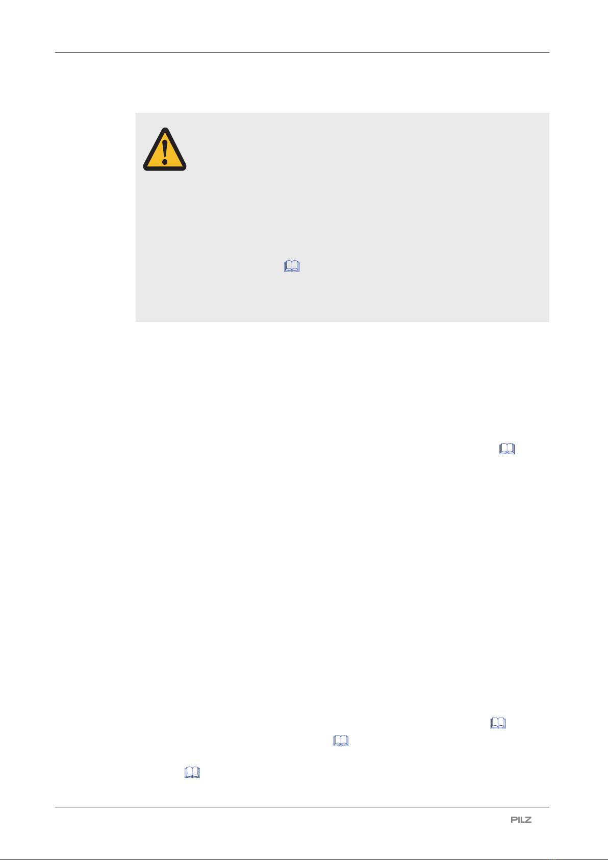
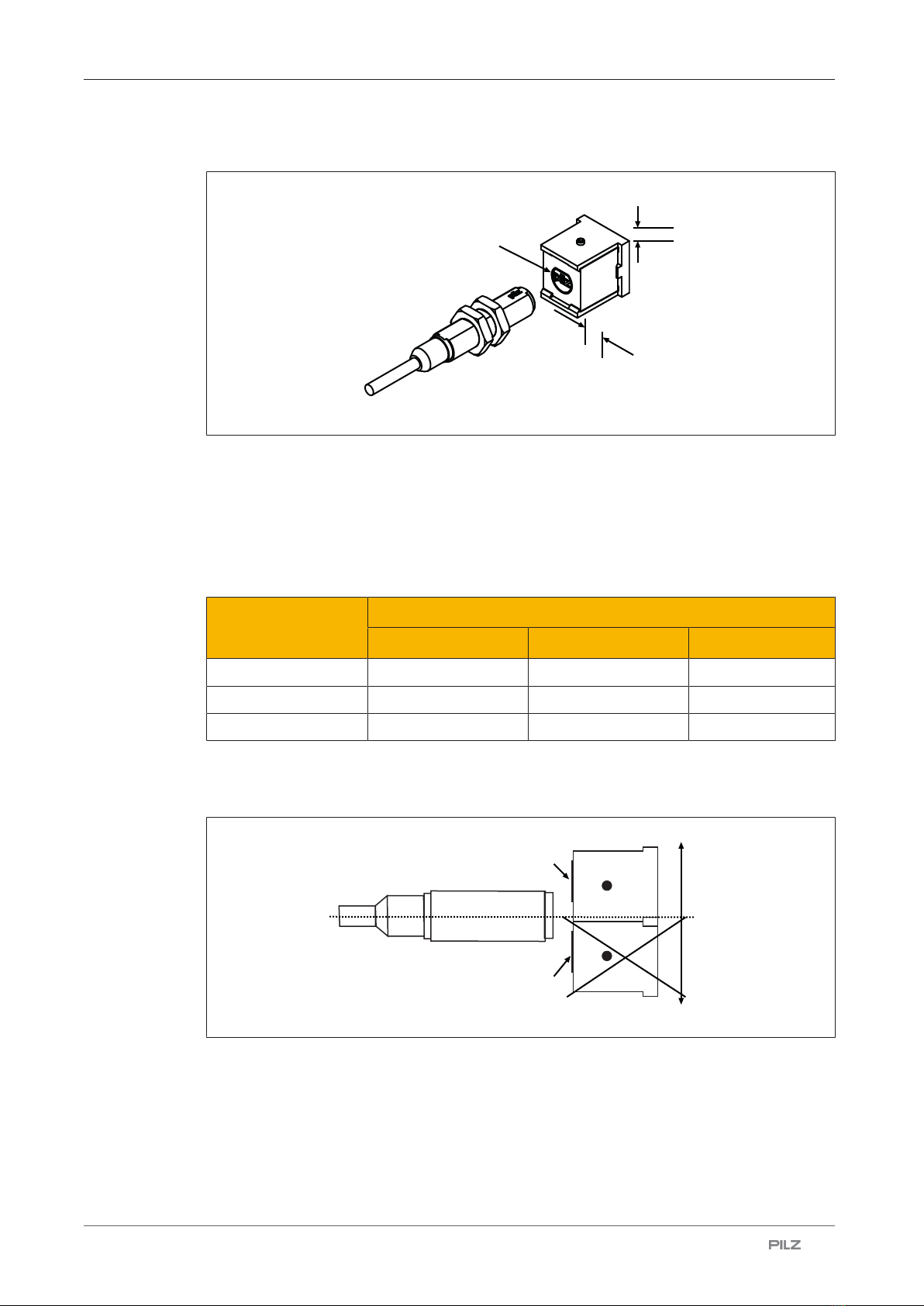
Lateral and vertical offset.......................................................................................................... 9
Wiring ......................................................................................................................................11
Pin assignment ......................................................................................................................... 11
Requirements and connection to evaluation devices ........................................................ 12
Installation ..............................................................................................................................15
Adjustment ............................................................................................................................. 18
Periodic test ...........................................................................................................................18
Dimensions in mm .................................................................................................................18
Technical details order no. 506221, 506231 ........................................................................ 19
Technical details order no. 506223, 506233 ........................................................................ 21
Safety characteristic data ..................................................................................................... 23
Order reference ......................................................................................................................24
System...................................................................................................................................... 24
Accessories .............................................................................................................................. 24
EC declaration of conformity ................................................................................................ 24

PSEN ma1.3a/b-22
Operating Manual PSEN ma1.3a/b-22
21737-EN-12 | 4
Introduction
Validity of documentation
This documentation is valid for the product PSEN ma1.3a/b-22. It is valid until new docu-
mentation is published.
This operating manual explains the function and operation, describes the installation and
provides guidelines on how to connect the product.
Using the documentation
This document is intended for instruction. Only install and commission the product if you
have read and understood this document. The document should be retained for future ref-
erence.
Definition of symbols
Information that is particularly important is identified as follows:
DANGER!
This warning must be heeded! It warns of a hazardous situation that poses
an immediate threat of serious injury and death and indicates preventive
measures that can be taken.
WARNING!
This warning must be heeded! It warns of a hazardous situation that could
lead to serious injury and death and indicates preventive measures that can
be taken.
CAUTION!
This refers to a hazard that can lead to a less serious or minor injury plus
material damage, and also provides information on preventive measures
that can be taken.
NOTICE
This describes a situation in which the product or devices could be dam-
aged and also provides information on preventive measures that can be
taken. It also highlights areas within the text that are of particular import-
ance.

PSEN ma1.3a/b-22
Operating Manual PSEN ma1.3a/b-22
21737-EN-12 | 5
INFORMATION
This gives advice on applications and provides information on special fea-
tures.
Safety
Intended use
The safety function of the safety switch is:
}Safe detection of the magnetic actuator within the response range
The safety switch meets the requirements in accordance with:
}EN 60947-5-3: PDDB only in connection
– with the operator PSEN ma1.3-08 or operator PSEN ma1.3-12
– the interface PSEN ix1 and
– the suitable evaluation devices (see Requirements and connection to evaluation
devices [ 12]).
The safety switch is designed for applications in series connections and it must only be op-
erated with the following components:
}Actuator PSEN ma1.3-08 or actuator PSEN ma1.3-12 ,
}interface PSEN ix1 (see Order reference [ 24]) and
}an approved evaluation device.
The following is deemed improper use in particular
}Any component, technical or electrical modification to the product,
}Use of the product outside the areas described in this manual,
}Use of the product outside the technical details (see Technical details [ 19]).
NOTICE
EMC-compliant electrical installation
The product is designed for use in an industrial environment. The product
may cause interference if installed in other environments. If installed in other
environments, measures should be taken to comply with the applicable
standards and directives for the respective installation site with regard to in-
terference.

PSEN ma1.3a/b-22
Operating Manual PSEN ma1.3a/b-22
21737-EN-12 | 6
Safety regulations
Safety assessment
Before using a device, a safety assessment in accordance with the Machinery Directive is
required.
The product as an individual component fulfils the functional safety requirements in accord-
ance with EN ISO 13849 and EN 62061. However, this does not guarantee the functional
safety of the overall plant/machine. To achieve the relevant safety level of the overall plant/
machine’s required safety functions, each safety function needs to be considered separ-
ately.
Use of qualified personnel
The products may only be assembled, installed, programmed, commissioned, operated,
maintained and decommissioned by persons who are competent to do so.
A competent person is a qualified and knowledgeable person who, because of their train-
ing, experience and current professional activity, has the specialist knowledge required. To
be able to inspect, assess and operate devices, systems and machines, the person has to
be informed of the state of the art and the applicable national, European and international
laws, directives and standards.
It is the company’s responsibility only to employ personnel who
}Are familiar with the basic regulations concerning health and safety / accident prevention,
}Have read and understood the information provided in the section entitled Safety
}Have a good knowledge of the generic and specialist standards applicable to the specific
application.
Warranty and liability
All claims to warranty and liability will be rendered invalid if
}The product was used contrary to the purpose for which it is intended,
}Damage can be attributed to not having followed the guidelines in the manual,
}Operating personnel are not suitably qualified,
}Any type of modification has been made (e.g. exchanging components on the PCB
boards, soldering work etc.).
Disposal
}In safety-related applications, please comply with the mission time TM in the safety-related
characteristic data.
}When decommissioning, please comply with local regulations regarding the disposal of
electronic devices (e.g. Electrical and Electronic Equipment Act).

PSEN ma1.3a/b-22
Operating Manual PSEN ma1.3a/b-22
21737-EN-12 | 7
For your safety
WARNING!
Loss of safety function due to manipulation of the interlocking device
Manipulation of the interlocking device may lead to serious injury and death.
– You should prevent any possibility of the interlocking device being
manipulated through the use of a spare actuator.
– Keep the substitute actuator in a safe place and protect it from unau-
thorised access.
– If spare actuators are used, these must be installed as described in
Installation [ 15].
– If the original actuators are replaced with substitute actuators, the ori-
ginal actuators must be destroyed before disposal.
Unit features
}The actuator PSEN ma1.3-08 or PSEN ma1.3-12 belongs to the safety switch.
}Coded actuator
}Safety switch with cable (5 m/ 10 m)
}2 safety contacts (reed contacts - N/O)
}1 auxiliary contact (N/O)
}Different operating distances depending on the actuator see Technical details [ 19]
}Design:
– Safety switch with round design
– Actuator with round design: PSEN ma1.3-08
– Actuator with square design: PSEN ma1.3-12 (various directions of actuation pos-
sible)
}Operation Magnetic
}Switching voltage 24 VDC
}Series connection via PSEN ix1 interface
}LED to display switch status
Function description
If the actuator is within the response range (safety gate closed), the safety contacts and the
auxiliary contact on the safety switch will be closed and the LED will light.
The safety switch is designed for applications in series connections.
Operate the PSEN ma1.3a/b-22 in conjunction with the following components:
}Actuator PSEN ma1.3-08 or actuator PSEN ma1.3-12 (see Order reference [ 24]),
}interface PSEN ix1 (see Order reference [ 24]) and
}a connected evaluation device (see Requirements and connection to evaluation
devices [ 12]).

PSEN ma1.3a/b-22
Operating Manual PSEN ma1.3a/b-22
21737-EN-12 | 8
Block diagram
3 5+1
42 6
Actuator
Safety switch
Magnet
Operating distances
Sao SoSrSar (mm)Somin
On
Off
Legend
Sao Assured operating distance
Somin Min. operating distance
Sar Assured release distance
The offset-independent values for the switching distances are included in the Technical
details [ 19].

PSEN ma1.3a/b-22
Operating Manual PSEN ma1.3a/b-22
21737-EN-12 | 9
Lateral and vertical offset
Actuator PSEN ma1.3-08
[2]
[1]
[3]
Legend
[1] Lateral offset
[2] Vertical offset
[3] Sensing faces
Assured operating distance Sao in mm
Lateral offset Vertical offset
0 2 4
08.0 7.0 5.5
27.0 6.0 4.0
46.0 5.0 3.0
The stated values are valid at a temperature of 20 °C.

PSEN ma1.3a/b-22
Operating Manual PSEN ma1.3a/b-22
21737-EN-12 | 10
Actuator PSEN ma1.3-12
[2]
[1]
[3]
Legend
[1] Lateral offset
[2] Vertical offset
[3] Sensing face
Assured operating distance Sao in mm
Lateral offset Vertical offset
012
012.0 10.0 8.0
212.0 10.0 8.0
411.0 9.5 7.5
The stated values are valid at a temperature of 20 °C.
Negative vertical offset, not permitted
[1]
[2]
[3]
[4]
[1]
Fig.: Safety switch and square actuator - side view
Legend
[1] Sensing face PSEN ma1.3-12
[2] Positive vertical offset, permitted
[3] Negative vertical offset, not permitted

PSEN ma1.3a/b-22
Operating Manual PSEN ma1.3a/b-22
21737-EN-12 | 11
[4] Safety switch
Wiring
}Information given in the Technical details [ 19] must be followed.
}Calculation of the max. cable length lmax:
Rlmax - Ri
Rl / km
Imax =
Rlmax = Max. overall cable resistance (see evaluation device's technical details)
Ri = Internal resistance sensor (see Technical details [ 19])
Rl/km = Cable resistance/km of the cable (seetechnical details cable)
}Ensure the wiring and EMC requirements of EN 60204-1 are met.
}In the following cases, check the function that detects shorts across contacts prior to
commissioning:
– On evaluation devices with DC supply voltage: Overall cable resistance ≥ 15 Ohms
per channel
– On evaluation devices with AC supply voltage: Overall cable resistance ≥ 25 Ohms
per channel
– For details of how to perform the test for shorts across the contacts, please refer to
the operating manual for the relevant evaluation device.
Pin assignment
NOTICE
The colour marking for the connection lead only applies for the cable that
Pilz supplies as an accessory
The safety switch is shown in an unoperated condition.
Layout of the 6-core cable
Green
White
Brown
Blue
Red
Black
1
2
3
4
5+
6
NOTICE
The auxiliary contact
– may only be operated with a supply voltage of up to 24 VDC
– can be connected in series
– maynot be used for safety circuits

PSEN ma1.3a/b-22
Operating Manual PSEN ma1.3a/b-22
21737-EN-12 | 12
Requirements and connection to evaluation devices
For use of PSEN ma1.3a/b-22 in accordance with DIN EN 60947-5-3 an evaluation device
must be connected.
Connect the PSEN ma1.3a/b-22
}either with a certified Pilz evaluation device
}or with an evaluation device with defined properties
Certified Pilz evaluation devices are, for example:
}PNOZelog for safety gate monitoring
– PNOZ e1p, PNOZ e1.1p, PNOZ e1vp
– PNOZ e5.11p
– PNOZ e6vp, PNOZ e6.1p
}PNOZpower for safety gate monitoring
– PNOZ p1p, PNOZ p1vp
}PNOZsigma for safety gate monitoring
– PNOZ s3
– PNOZ s4
– PNOZ s5
}PNOZ X for safety gate monitoring
– PNOZ X2, PNOZ X2.5P, PNOZ X2.7P, PNOZ X2.8P, PNOZ X2.9P, PNOZX2C
– PNOZ X3, PNOZ X3.1, PNOZ X3P, PNOZ X3.10P
– PNOZ X4
– PNOZ X5, PNOZ X5J
– PNOZ Ex
}PNOZmulti for safety gate monitoring
Configure the switch in the PNOZmulti Configurator with switch type 3.
}PSS for safety gate monitoring with standard function block SB064, SB066 or
FS_SafetyGate
}PSSuniversal PLC for safety gate monitoring with function block FS_SafetyGate
The correct connection to the respective evaluation device is described in the operating
manual for the evaluation device. Make sure that the connection is made in accordance
with the specifications in the operating manual for the selected evaluation device.
Defined properties of evaluation devices:
}2-channel with feasibility monitoring
}Open circuit monitoring of the safety switch is performed
}Inputs and outputs on the evaluation device must fulfil the requirements of IEC61131,
Type 3

PSEN ma1.3a/b-22
Operating Manual PSEN ma1.3a/b-22
21737-EN-12 | 13
}Technical data of the evaluation device must fulfil the requirements in the Technical
details [ 19] of PSEN ma1.3a/b-22
– Always comply with the max. switching current safety contacts of PSEN ma1.3a/b-22.
}Outputs at the evaluation device must only be switched on again when both reed con-
tacts at the safety switch have been opened and closed (partial operation lock)
INFORMATION
Risk time in accordance with DIN EN 60947-5-3
The risk time is made up of the reaction time of the sensor (see Technical
details [ 19]) and the processing and delay times of the evaluation
device (s. operating manual for the relevant evaluation device).
Y1 Y8
A2A1
11 12
14
Y2 Y3 Y4Y5 Y6 Y9
1 2 3 4
13 23 24
21 22 31
33 34
32 41
43 44
42
A1 A2
1 2 3 4
11 12 1413
1 2 3 4
21 22 2423
1 2 3 4
31 33 3432
1 2 3 4
41 43 4442
+24 V
I0.0
I0.1
I0.2
I0.3
+24 V
0 V
PSEN ix1
PLC
PSENmag
Evaluation device
Input circuit
Input circuit
Fig.: Dual-channel connection of four PSENmag to the input circuits of an evaluation device

PSEN ma1.3a/b-22
Operating Manual PSEN ma1.3a/b-22
21737-EN-12 | 14
Examples for connection to Pilz evaluation devices:
S21
S22
S11
S12
PNOZ s3 PSENmag
3
1
2
4
5+
6
PSEN ix1
3
1
2
4
11
12
13
14
Brown
White
Blue
Black
I0
I1
PNOZmulti PSENmag
T1
T0
PSEN ix1
3
1
2
4
11
12
13
14
3
1
2
4
5+
6
Brown
White
Blue
Black
Auxiliary contact with LED
The auxiliary contact and the LED indicate the status of the safety contacts.
Actuator in the response range Safety contacts and auxili-
ary contact
LED
Yes Closed lights
No Open Off
1
2
3
4
5+
6
24 V
GND
PSENmag
1
2
3
4
5+
6
24 V
PLC
PSENmag
Connecting the auxiliary contact to an eval-
uation device
Connecting the auxiliary contact to a PLC

PSEN ma1.3a/b-22
Operating Manual PSEN ma1.3a/b-22
21737-EN-12 | 15
Installation
}The unit can be installed in any position. Safety switches and actuators must be installed
so that the bevelled surface on the safety switch and the bevelled surface of the actuator
face each other precisely.
CAUTION!
Potential loss of safety function due to changed device properties
The unit's properties may be affected if installed in an environment contain-
ing electrically or magnetically conductive material.
– Please check the operating distances and the assured release dis-
tance.
CAUTION!
Possible loss of the safety function by changing the release distance
Sar with non-flush installation
Installing the safety switch non-flush within electrically or magnetically con-
ductive material, the value for the assured release distance Sar can change.
– Check the assured release distance Sar.
}Safety switches and actuators must be positioned so that they are secured against a
change of position.
}Attach the safety switches and actuators only with the supplied nuts.
}Avoid the risk of damages from foreseeable external influences by attaching the safety
switch and actuator. If necessary, safety switch and actuator have to be protected.
INFORMATION
Protect the actuator from unauthorised removal (e.g. via a screw lock or
concealed installation) and from contamination.
}Prevent self-loosening of the fastening elements of safety switch and actuator.
}The fastening of safety switch and actuator has to be sufficiently stable to ensure the
proper operation of the safety switch and the actuator.
}The distance between two safety switches must be maintained (see Technical
details [ 19]).
}Safety switches and actuators
– Should be kept away from iron swarf
– Should not be exposed to strong magnetic fields
}Prevent the safety switch and actuator being exposed to heavy shock or vibration.
}Make sure that the safety switch and actuator cannot be used as an end stop.
}Circumvention of the safety switch in a reasonably foreseeable manner must be preven-
ted.

PSEN ma1.3a/b-22
Operating Manual PSEN ma1.3a/b-22
21737-EN-12 | 16
}Please note the installation measures in accordance with EN ISO 14119 for a proximity
switch type 4 with coding level Low.
}Alignment errors of the guard must not adversely affect the safety function of the guard.
}The assured operating distance Sao and the assured release distance Sar must be tested
under real conditions.
}Do not apply any installation tools (e.g. Pliers) on the surfaces of the switch.
}If possible, do not install the safety switch and actuator on to ferromagnetic material.
Changes to the operating distances are to be expected.
}Protect the safety switch and actuator from UV light or direct sunlight.
Installation of safety switch
Sensing face
Slide the switch through the hole in the
mounting surface with the sensing face to-
wards the actuator.
Attach the switch using 2 M12
hexagonal nuts with special threads.
Note the max. torque setting (see Tech-
nical details [ 19]).
Installation with actuator PSEN ma1.3-08
Sensing face
Slide the actuator through the hole in the
mounting surface with the sensing face to-
wards the safety switch.

PSEN ma1.3a/b-22
Operating Manual PSEN ma1.3a/b-22
21737-EN-12 | 17
Attach the actuator using 2 M12 hexagonal
nuts with special threads.
Note the max. torque setting (see Technical
details [ 19]).
Installation with actuator PSEN ma1.3-12
Attach the bracket using countersunk
screws (M4).
Sensing face
The sensing face at the actuator is marked
by a circle with a bevelled surface in the
shape of the safety switch. The sensing
face can be aligned in 3 directions depend-
ing on the direction of actuation. Slide the
actuator on to the bracket in the required
direction of actuation until the actuator clicks
into place.
The actuator should be secured using a set
screw M3 x 6 mm DIN 319 (supplied with
the device).
Also note the low max. torque setting (see
Technical details [ 19]).

PSEN ma1.3a/b-22
Operating Manual PSEN ma1.3a/b-22
21737-EN-12 | 18
Adjustment
}The safety switch may only be used with the corresponding actuator PSEN ma1.3-08 or
PSEN ma1.3-12.
}Always test the function with the PSEN ix1 interface and connected evaluation device.
}The stated operating distances (see Technical details [ 19]) only apply when the
safety switch and actuator are installed according to the specifications
Installation [ 15]. Operating distances may deviate if other arrangements are used.
Note the maximum permitted lateral and vertical offset (see Operating distances and Lat-
eral and vertical offset [ 8]).
Periodic test
}Carry out a monthly function test on the safety switch and actuator.
}Always test the function with the PSEN ix1 interface and connected evaluation device.
}The safety function may only be checked by qualified personnel.
Dimensions in mm
Safety switch
2
42,6 2 12,5
59,1
M12x1
11
Actuator PSEN ma1.3-08
M12x1
11
221
25
2
Actuator PSEN ma1.3-12
20 10
M12
20
20
10
M3

PSEN ma1.3a/b-22
Operating Manual PSEN ma1.3a/b-22
21737-EN-12 | 19
20
5
24,1
107
59,6
2xø9
2xø4,5
20
26,5
Fig.: Actuator holder
Technical details order no. 506221, 506231
General 506221 506231
Certifications CE, EAC (Eurasian), ECOLAB,
TÜV, cULus Listed
CE, EAC (Eurasian), ECOLAB,
TÜV, UL/cUL, cULus Listed
Sensor's mode of operation Magnetic Magnetic
Coding level in accordance with EN
ISO 14119 Low Low
Design in accordance with EN ISO
14119 4 4
Classification in accordance with
EN 60947-5-3 PDDB PDDB
Electrical data 506221 506231
Supply voltage
Voltage 24 V 24 V
Kind DC DC
Voltage tolerance -20 %/+20 % -20 %/+20 %
Supply voltage
Max. current 150 mA 150 mA
Max. switching frequency 1 Hz 1 Hz
Lowest operating current (Im) 1 mA 1 mA
Switching voltage 24 V 24 V
Internal resistance 0 Ohm 0 Ohm
Max. switching current, safety con-
tacts 0,2 A 0,2 A
Max. breaking capacity, safety con-
tacts 5 W 5 W
Max. switching current, auxiliary
contacts 10 mA 10 mA
Times 506221 506231
Reaction time (actuator removed) 2 ms 2 ms

PSEN ma1.3a/b-22
Operating Manual PSEN ma1.3a/b-22
21737-EN-12 | 20
Environmental data 506221 506231
Ambient temperature
Temperature range -25 - 70 °C -25 - 70 °C
Climatic suitability
In accordance with the standard IEC 60068-2-30 IEC 60068-2-30
Humidity 93 % r. h. at 40 °C 93 % r. h. at 40 °C
Max. operating height above sea
level 2000 m 2000 m
EMC EN 60947-5-3 EN 60947-5-3
Vibration
In accordance with the standard EN 60947-5-2 EN 60947-5-2
Frequency 10 - 55 Hz 10 - 55 Hz
Amplitude 1 mm 1 mm
Shock stress
Acceleration 30g 30g
Duration 11 ms 11 ms
Airgap creepage
Pollution degree 3 3
Rated insulation voltage 250 V 250 V
Rated impulse withstand voltage 4 kV 4 kV
Protection type
Housing IP65 IP65
Operating distances 506221 506231
Assured operating distance Sao 8 mm 12 mm
Min. operating distance Somin 0,5 mm 0,5 mm
Typical operating distance So 10 mm 14 mm
Assured release distance Sar 15 mm 25 mm
Typical release distance Sr 12 mm 16 mm
Repetition accuracy switching dis-
tances 5 % 5 %
Mechanical data 506221 506231
Actuator 1 PSEN ma1.3-08 PSEN ma1.3-12
Typ. Hysteresis 2 mm 2,5 mm
Min. distance between safety
switches 25 mm 35 mm
Sensor flush installation in accord-
ance with EN 60947-5-2
Yes, follow installation
guidelines
Yes, follow installation
guidelines
Connection type 5 m cable 5 m cable
Cable LiY11Y 6 x 0,25 mm2 LiY11Y 6 x 0,25 mm2
Material
Top PBT PBT
Max. torque setting
Safety switch 3 Nm 3 Nm
Actuator 1 3 Nm 0,1 Nm
Table of contents
Other Pilz Control Unit manuals

Pilz
Pilz PDP67 F 8DI ION User manual

Pilz
Pilz PNOZmulti 2 User manual

Pilz
Pilz PSSu E F 4DO 0.5 User manual

Pilz
Pilz PNOZ mc6p User manual

Pilz
Pilz PNOZ mc1p User manual

Pilz
Pilz PNOZ m EF 4DI4DOR User manual

Pilz
Pilz PNOZ mo4p User manual

Pilz
Pilz PSSu K S RS232 Modbus ASCII User manual

Pilz
Pilz PNOZ m ES ETH User manual

Pilz
Pilz PSSu E F 2DO 2 User manual

Pilz
Pilz PSSu K F FAU B User manual

Pilz
Pilz PSSu E F PS2 User manual

Pilz
Pilz PSSu E F BSW User manual

Pilz
Pilz PSSu E S 2AI RTD User manual

Pilz
Pilz PNOZ mc10p User manual

Pilz
Pilz PNOZ m ES ETH User manual

Pilz
Pilz PNOZ m EF 1MM User manual

Pilz
Pilz PSS u2 ES 8DI User manual

Pilz
Pilz P1HZ X1 User manual

Pilz
Pilz PNOZ po3.1p User manual