- 2 -
Blockschaltbild/Klemmenbelegung Block diagram/terminal configuration 内部回路ブ ロ ッ ク図 /端子配列
*Sichere Trennung nach EN 60947-1, 6 kV
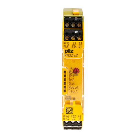
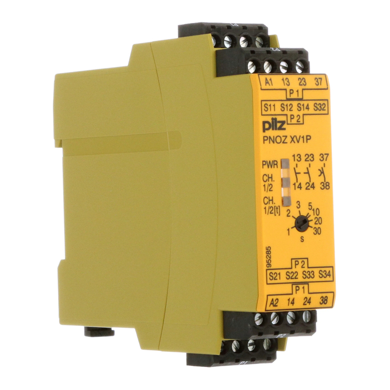
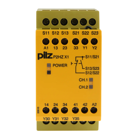
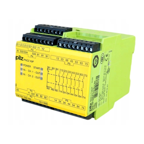
Mitte: Frontansicht mit Abdeckung
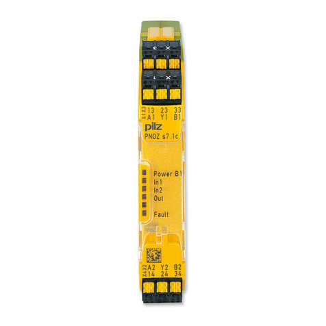
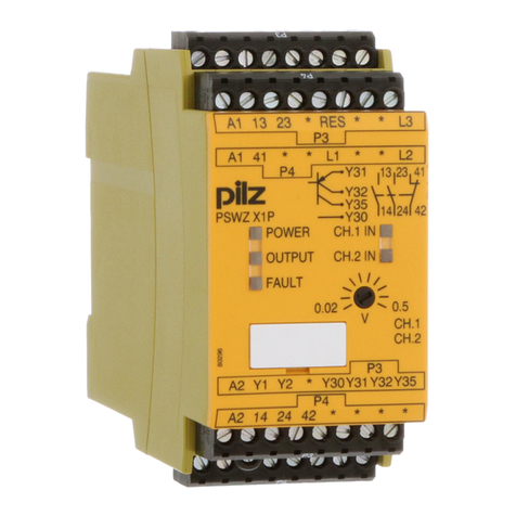
Rechts: Frontansicht ohne Abdeckung
*Safe separation in accordance with
EN 60947-1, 6 kV
Centre: Front view with cover
Right: Front view without cover
* EN 60947-1 に基づ く 安全な絶縁、 6kV
中央 : 正面図 (カバー付き)
右:正面図 (カバーなし)
Funktionsbeschreibung
Einkanaliger Betrieb: keine Redundanz im Ein-
gangskreis, Erdschlüsse im Start- und Eingangs-
kreis werden erkannt.
Automatischer Start: Gerät wird aktiv, nach-
dem Eingangskreis geschlossen wurde.
Manueller Start: Gerät wird aktiv, wenn der
Eingangskreis geschlossen ist und danach der
Startkreis geschlossen wird.
Überwachter Start mit steigender Flanke: Ge-
rät wird aktiv, wenn der Eingangskreis ge-
schlossen ist und nach Ablauf der Wartezeit
(s. techn. Daten) der Startkreis geschlossen
wird.
Überwachter Start mit fallender Flanke: Ge-
rät wird aktiv, wenn
– der Eingangskreis geschlossen ist und da-
nach der Startkreis geschlossen und wieder
geöffnet wird.
– der Startkreis geschlossen und nach
Schließen des Eingangskreises wieder ge-
öffnet wird.
Kontaktvervielfältigung und –verstärkung der un-
verzögerten Sicherheitskontakte durch Verdrah-
tung von Kontakterweiterungs-
blöcken oder externen Schützen möglich;
1 Kontakterweiterungsblock PNOZsigma über
Verbindungsstecker anschließbar.
Function description
Single-channel operation: no redundancy in the
input circuit, earth faults in the reset and input cir-
cuit are detected.
Automatic reset: Unit is active once the input
circuit has been closed.
Manual reset: Unit is active once the input
circuit is closed and then the reset circuit is
closed.
Monitored reset with rising edge: Unit is ac-
tive once the input circuit is closed and once
the reset circuit is closed after the waiting pe-
riod has elapsed (see technical details).
Monitored reset with falling edge: Unit is ac-
tive once
– the input circuit is closed and then the reset
circuit is closed and opened again.
– the reset circuit is closed and then opened
again once the input circuit is closed.
Increase in the number of available instantaneous
safety contacts by connecting contact expander
modules or external contactors/relays;
A connector can be used to connect 1 PNOZsigma
contact expander module.
機能の概要
1 チ ャ ンネル運転 : 非冗長入力回路、 リ セ ッ
ト 回路および入力回路の地絡検出
自動 リ セ ッ ト : 入力回路が閉 じ れば、 ユ
ニッ トは起動します。
手動 リ セ ッ ト : 入力回路が閉 じ た後 リ
セ ッ ト 回路が閉じ れば、 ユニ ッ ト は起動
します。
立上 り モニ タ リ ン グ リ セ ッ ト : 入力回路
が閉じ た後、 待機時間経過後に リ セ ッ ト
回路が閉じ れば、 ユニ ッ ト は起動し ます
(詳細は、 技術デー タ を参照 く だ さ い)。
立下り モニ タ リ ング リ セ ッ ト : ユニ ッ ト
は以下の場合に起動 し ます。
–入力回路が閉 じ た後、 リ セ ッ ト 回路
が閉じ て再度開いた場合
–リ セ ッ ト 回路が閉 じ て、 入力回路が
閉じた後、 リセッ ト回路を再度開い
た場合
接点増設モ ジ ュールや外部の コ ン タ ク タ ・
リ レーな どに接続 し 、 瞬時安全接点数を増
設;
コネクタを使用して PNOZsigma 接点増設モ
ジ ュール 1 台を接続可能。
Montage
Grundgerät ohne Kontakterweiterungsblock montie-
ren:
Stellen Sie sicher, dass der Abschluss-
stecker seitlich am Gerät gesteckt ist.
Grundgerät und Kontakterweiterungsblock PNOZ-
sigma verbinden:
Entfernen Sie den Abschlussstecker seitlich am
Grundgerät und am Kontakter-
weiterungsblock.
Verbinden Sie das Grundgerät und den Kontakter-
weiterungsblock mit dem mitgelieferten Verbin-
dungsstecker bevor Sie die Geräte auf der
Normschiene montieren.
Montage im Schaltschrank
Montieren Sie das Sicherheitsschaltgerät in einen
Schaltschrank mit einer Schutzart von mindestens
IP54.
Befestigen Sie das Gerät mit Hilfe des Rastele-
ments auf der Rückseite auf einer Normschiene.
Sichern Sie das Gerät auf einer senkrechten
Normschiene (35 mm) durch ein Halteelement
(z. B. Endhalter oder Endwinkel).
Vor dem Abheben von der Normschiene das Ge-
rät nach oben oder unten schieben.
Installation
Install base unit without contact expander module:
Ensure that the plug terminator is inserted at the
side of the unit.
Connect base unit and PNOZsigma contact expander
module:
Remove the plug terminator at the side of the base
unit and at the contact expander module.
Connect the base unit and the contact expander
module to the supplied connector before mount-
ing the units to the DIN rail.
Installation in control cabinet
The safety relay should be installed in a control
cabinet with a protection type of at least IP54.
Use the notch on the rear of the unit to attach it to
a DIN rail.
Ensure the unit is mounted securely on a vertical
DIN rail (35 mm) by using a fixing element (e.g.
retaining bracket or an end angle).
Push the unit upwards or downwards before lift-
ing it from the DIN rail.
取り付け
ベースユニ ッ ト の取 り 付け (接点増設
モジュールなし) :
ユニ ッ ト の側面にプ ラグ ター ミ ネータが挿
入されているこ とを確認して く ださい。
ベースユニ ッ ト と PNOZsigma 接点増設
モジ ュ ールの接続 :
ベースユニ ッ ト 側面 と接点増設モ ジ ュール
のプラグ ター ミ ネータ を取り外し て く だ さ
い。
ユニッ ト を DIN レールに取り付ける前に、付
属の コ ネ ク タ を用いてベースユ ニ ッ ト と 接
点増設モ ジ ュールを接続 し て く だ さ い。
制御盤への取 り 付け
安全 リ レ ーは、 保護構造が少な く と も IP54
の制御盤に取 り 付け る必要があ り ま す。
ユニ ッ ト の背面にある ノ ッ チ を使用 し て、
DIN レールに取り付けます。
固定器具 (固定ブ ラ ケ ッ ト やエ ン ド ア ン グ
ルなど) を使用 して、 ユニ ッ ト が DIN レー
ル(35 mm) に垂直にし っかり と固定されて
いるこ と を確認して く ださい。
DIN レ ールか らユニ ッ ト を取 り 外す際は、 ユ
ニ ッ ト を上方向または下方向に押 し て取 り
外して く ださい。
Input
A1 A2
=
Power
Reset/
Start
S34
=
Y32
K1
K2
13 23 33 41
24 34 42
14
Interface
expansion
unit
*
