Pilz PNOZ X3.10P User manual

- 1 -
Safety Regulations
• The unit may only be installed and
operated by personnel who are familiar
with both these instructions and the
current regulations for safety at work and
accident prevention.
• Follow VDE and local regulations
especially as regards preventative
measures.
• Transport, storage and operating
conditions should all conform to
EN 60068-2-78.
• Any guarantee is void following opening
of the housing or unauthorised
modifications.
• The unit should be panel mounted,
otherwise dampness or dust could lead to
function impairment.
• Adequate protection must be provided on
all output contacts especially with
capacitive and inductive loads.
Sicherheitsbestimmungen
• Das Gerät darf nur von Personen
installiert und in Betrieb genommen
werden, die mit dieser Betriebsanleitung
und den geltenden Vorschriften über
Arbeitssicherheit und Unfallverhütung
vertraut sind.
• Beachten Sie die VDE- sowie die
örtlichen Vorschriften, insbesondere
hinsichtlich Schutzmaßnahmen.
• Beim Transport, der Lagerung und im
Betrieb die Bedingungen nach EN 60068-
2-78 einhalten (s. technische Daten).
• Durch Öffnen des Gehäuses oder eigen-
mächtige Umbauten erlischt jegliche Ge-
währleistung.
• Montieren Sie das Gerät in einen
Schaltschrank; Staub und Feuchtigkeit
können sonst zu Beeinträchtigungen der
Funktionen führen.
• Sorgen Sie an allen Ausgangskontakten
bei kapazitiven und induktiven Lasten für
eine ausreichende Schutzbeschaltung.
Conseils préliminaires
• La mise en oeuvre de l’appareil doit être
effectuée par une personne spécialisée
en installations électriques, en tenant
compte des prescriptions des différentes
normes applicables (NF, EN, VDE...)
notamment au niveau des risques
encourus en cas de défaillance de
l’équipement électrique.
• Respecter les exigences de la norme
EN 60068-2-78 lors du transport, du
stockage et de l'utilisation de l'appareil.
• L’ouverture de l’appareil ou sa modifi-
cation annule automatiquement la
garantie.
• L’appareil doit être monté dans une ar-
moire; l’humidité et la poussière pouvant
entraîner des aléas de fonctionnement.
• Vérifiez que le pouvoir de coupure des
contacts de sortie est suffisant en cas de
circuits capacitifs ou inductifs.
Bestimmungsgemäße Verwendung
Das Sicherheitsschaltgerät dient dem
sicherheitsgerichteten Unterbrechen eines
Sicherheitsstromkreises. Das Sicherheits-
schaltgerät erfüllt Forderungen der
EN 60947-5-1, EN 60204-1 und
VDE 0113-1 und darf eingesetzt werden in
Anwendungen mit
• Not-Halt-Tastern
• Schutztüren
• Lichtschranken
Gerätebeschreibung
Das Sicherheitsschaltgerät PNOZ X3.10P
ist in einem P-99-Gehäuse untergebracht.
Es kann mit 24 V Gleichspannung oder
Wechselspannung betrieben werden.
Merkmale:
• Relaisausgänge: 3 Sicherheitskontakte
(Schließer) und ein Hilfskontakt (Öffner),
zwangsgeführt
• Anschlussmöglichkeit für Not-Halt-Taster,
Schutztürgrenztaster und Starttaster
• Statusanzeigen
• Überwachung externer Schütze möglich
• Halbleiterausgang meldet Betriebsbereit-
schaft
Das Schaltgerät erfüllt folgende Sicherheits-
anforderungen:
• Schaltung ist redundant mit Selbst-
überwachung aufgebaut (EN 954-1
Kategorie 4).
• Sicherheitseinrichtung bleibt auch bei
Ausfall eines Bauteils wirksam.
• Bei jedem Ein-Aus-Zyklus der Maschine
wird automatisch überprüft, ob die Relais
der Sicherheitseinrichtung richtig öffnen
und schließen.
• Das Gerät hat eine elektronische Siche-
rung.
Authorised Applications
The safety relay provides a safety-related
interruption of a safety circuit. The safety
relay meets the requirements of EN 60947-
5-1, EN 60204-1 and VDE 0113-1 and may
be used in applications with
• E-STOP pushbuttons
• Safety gates
• Light barriers
Domaines d’utilisation
Le bloc logique de sécurité sert à
interrompre en toute sécurité un circuit de
sécurité. Le bloc logique de sécurité satisfait
aux exigences des normes EN 60947-5-1,
EN 60204-1 et VDE 0113-1 et peut être
utilisé dans des applications avec des
• poussoirs d'arrêt d'urgence
• protecteurs mobiles
• barrières immatérielles
Description de l’appareil
Inséré dans un boîtier P-99, le bloc logique
de sécurité PNOZ X3.10P peut être
alimenté en 24 VAC/DC.
Particularités :
• Sorties disponibles : 3 contacts à
fermeture de sécurité et un contact à
ouverture pour signalisation
• Bornes de raccordement pour poussoirs
AU, détecteurs de position et poussoir de
validation
• LEDs de visualisation
• Auto-contrôle possible des contacteurs
externes
• Sorties statique d'information (relais en
position travail)
Le relais PNOZ X3.10P répond aux
exigences suivantes :
• conception redondante avec auto-
surveillance (selon EN 954-1 cat. 4)
• sécurité garantie même en cas de
défaillance d’un composant
• test cyclique (ouverture/fermeture des
relais internes) à chaque cycle Marche/
Arrêt de la machine
• Le relais dispose d'un fusible
électronique.
20 874-02
PNOZ X3.10P
4D Betriebsanleitung
4GB Operating instructions
4F Manuel d'utilisation
4E Instrucciones de uso
4I Istruzioni per l`uso
4NL Gebruiksaan ijzing
Description
The Safety Relay PNOZ X3.10P is enclosed
in a 45 mm P-99 housing. The unit can be
operated with 24 VAC/DC.
Features:
• Relay outputs: 3 safety contacts (N/O)
and one auxiliary contact (N/C), positive-
guided
• Connections for Emergency Stop Button,
Safety Gate Limit Switch and Reset
button
• Status Indicators
• Monitoring of external contactors/relays
possible
• Semi-conductor outputs show ready for
operation
The relay complies with the following safety
requirements:
• The circuit is redundant with built-in self-
monitoring (EN 954-1 Category 4).
• The safety function remains effective in
the case of a component failure.
• The correct opening and closing of the
safety function relays is tested
automatically in each on-off cycle.
• The relays has an electronic fuse.

- 2 -
Function Description
The relay PNOZ X3.10P provides a safety-
oriented interruption of a safety circuit.
When the operating voltage is supplied the
LED "Power" is illuminated. The unit is
ready for operation, when the reset circuit
S13-S14 is closed or a reset contact at S33-
S34 was opened and closed again.
• Input Circuit closed (e.g. the Emergency
Stop button is not pressed):
Relays K1and K2 energise and retain
themselves. The status indicators for
"CH. 1" and "CH. 2" illuminate. The
safety contacts (13-14/23-24/33-34) are
closed, the auxiliary contact (41-42) is
open.
• Input Circuit is opened (e.g. Emergency
Stop is pressed)
Relays K1 and K2 de-energise. The
status indicators for "CH.1" and "CH.2" go
out. The safety contacts (13-14/23-24/33-
34) will be opened (redundant), the
auxiliary contact (41-42) closes.
Semi-conductor output
The semi-conductor Y32 conducts if the
relays K1 and K2 are energised. Y32
switches off when the relays de-energise to
rest position.
Funktionsbeschreibung
Das Schaltgerät PNOZ X3.10P dient dem
sicherheitsgerichteten Unterbrechen eines
Sicherheitsstromkreises. Nach Anlegen der
Versorgungsspannung leuchtet die LED
"Power". Das Gerät ist betriebsbereit, wenn
der Startkreis S13-S14 geschlossen ist oder
ein Startkontakt an S33-S34 geöffnet und
wieder geschlossen wurde.
• Eingangskreis geschlossen (z. B. Not-
Halt-Taster nicht betätigt):
Relais K1 und K2 gehen in Wirkstellung
und halten sich selbst. Die Statusan-
zeigen für "CH. 1" und "CH. 2" leuchten.
Die Sicherheitskontakte (13-14/23-24/33-
34) sind geschlossen, der Hilfskontakt
(41-42) ist geöffnet.
• Eingangskreis wird geöffnet (z. B. Not-
Halt-Taster betätigt):
Relais K1 und K2 fallen in die Ruhe-
stellung zurück. Die Statusanzeige für
"CH. 1" und "CH. 2" erlischt. Die
Sicherheitskontakte (13-14/23-24/33-34)
werden redundant geöffnet, der Hilfs-
kontakt (41-42) geschlossen.
Halbleiterausgang
Der Halbleiterausgang Y32 leitet, wenn die
Relais K1 und K2 in Wirkstellung sind. Er
sperrt, wenn die Relais in Ruhestellung sind.
Description du fonctionnement
Le relais PNOZ X3.10P assure de façon
sure, l’ouverture d’un circuit de sécurité. A
la mise sous tension du relais (A1-A2), la
LED "Power" s'allume. Le relais est activé si
le circuit de réarmement S13-S14 est fermé
ou si le contact de réarmement sur S33-S34
a été ouvert puis refermé.
• Circuits d'entrée fermés (poussoir AU non
actionné) :
Les relais K1 et K2 passent en position
travail et s'auto-maintiennent. Les LEDs
"CH.1" et CH.2" s'allument. Les contacts
de sécurité (13-14/23-24/33-34) sont
fermés et le contact d'info. (41-42) est
ouvert.
• Circuits d'entrée ouverts (poussoir AU
actionné) :
Les relais K1 et K2 retombent. Les LEDs
"CH.1" et "CH.2" s'éteingnent. Les
contacts de sécurité (13-14/23-24/33-34)
s'ouvrent et le contact d'info. (41-42) se
ferme.
Sortie statique
La sortie statique Y32 est passante si les
relais K1 et K2 sont en position travail. Elle
est bloquée si les relais sont en position
repos.
Fig. 1: Innenschaltbild/Internal Wiring Diagram/Schéma de principe
Betriebsarten:
• Einkanaliger Betrieb:
Eingangsbeschaltung nach VDE 0113-1
und EN 60204-1, keine Redundanz im
Eingangskreis, Erdschlüsse im Tasterkreis
werden erkannt.
• Zweikanaliger Betrieb: Redundanter Ein-
gangskreis, Erdschlüsse im Tasterkreis
und Querschlüsse zwischen den Taster-
kontakten werden erkannt.
• Automatischer Start: Gerät ist aktiv,
sobald der Eingangskreis geschlossen ist.
• Manueller Start: Gerät ist erst dann aktiv,
wenn ein Starttaster betätigt wird.
• Manueller Start mit Überwachung: Gerät
ist nur aktiv, wenn vor dem Schließen des
Eingangskreises der Startkreis geöffnet
wird und der Startkreis nach dem Schlie-
ßen des Eingangskreises und nach Ablauf
der Wartezeit (s. techn. Daten) geschlos-
sen wird. Dadurch ist eine automatische
Aktivierung und Überbrückung des
Starttasters ausgeschlossen.
Operating Modes
• Single-channel operation: Input wiring
according to VDE 0113-1 and
EN 60204-1, no redundancy in the input
circuit. Earth faults are detected in the
emergency stop circuit.
• Two-channel operation: Redundancy in
the input circuit. Earth faults in the
Emergency Stop circuit and shorts across
the emergency stop push button are also
detected.
• Automatic reset: Unit is active as soon as
the input circuit is closed.
• Manual reset: Unit is only active when a
reset button has been pressed.
• Manual reset with monitoring: Unit will
only be active if the reset circuit is opened
before the input circuit closes, and the
reset circuit is closed after the input circuit
has closed and the waiting time has
elapsed (see technical data). This
eliminates the possibility of the reset
button being overridden, triggering
automatic activation.
Modes de fonctionnement
• Commande par 1 canal : conforme aux
prescriptions de la EN 60204/1, pas de
redondance dans le circuit d’entrée. La
mise à la terre du circuit d’entrée est
détectée
• Commande par 2 canaux : circuit d’entrée
redondant. La mise à la terre et les
courts-circuits entre les contacts sont
détectés.
• Réarmement automatique : le relais est
activé dès la fermeture des canaux
d’entrée.
• Réarmement manuel : le relais n’est
activé qu’après une impulsion sur un
poussoir de validation.
• Réarmement manuel auto-contrôlé :
L'appareil est uniquement actif lorsque le
circuit de réarmement est ouvert avant
fermeture des circuits d'entrées et que le
circuit de réarmement est fermé après
fermeture des circuits d'entrées et
écoulement du temps d'attente (voir les
caractéristiques techniques). Cette
mesure permet d'éviter toute activation
automatique et toute inhibition du
poussoir de réarmement.
A1 A2 S13S14 S12
S21
S34 41
42
S11
S22
S32S31 13 33
14 34
K1
K2
23
24
&
Y32
Y31
CH1
CH2 Start
Unit
S33
Y30
S16
S15
A1 A2

- 3 -
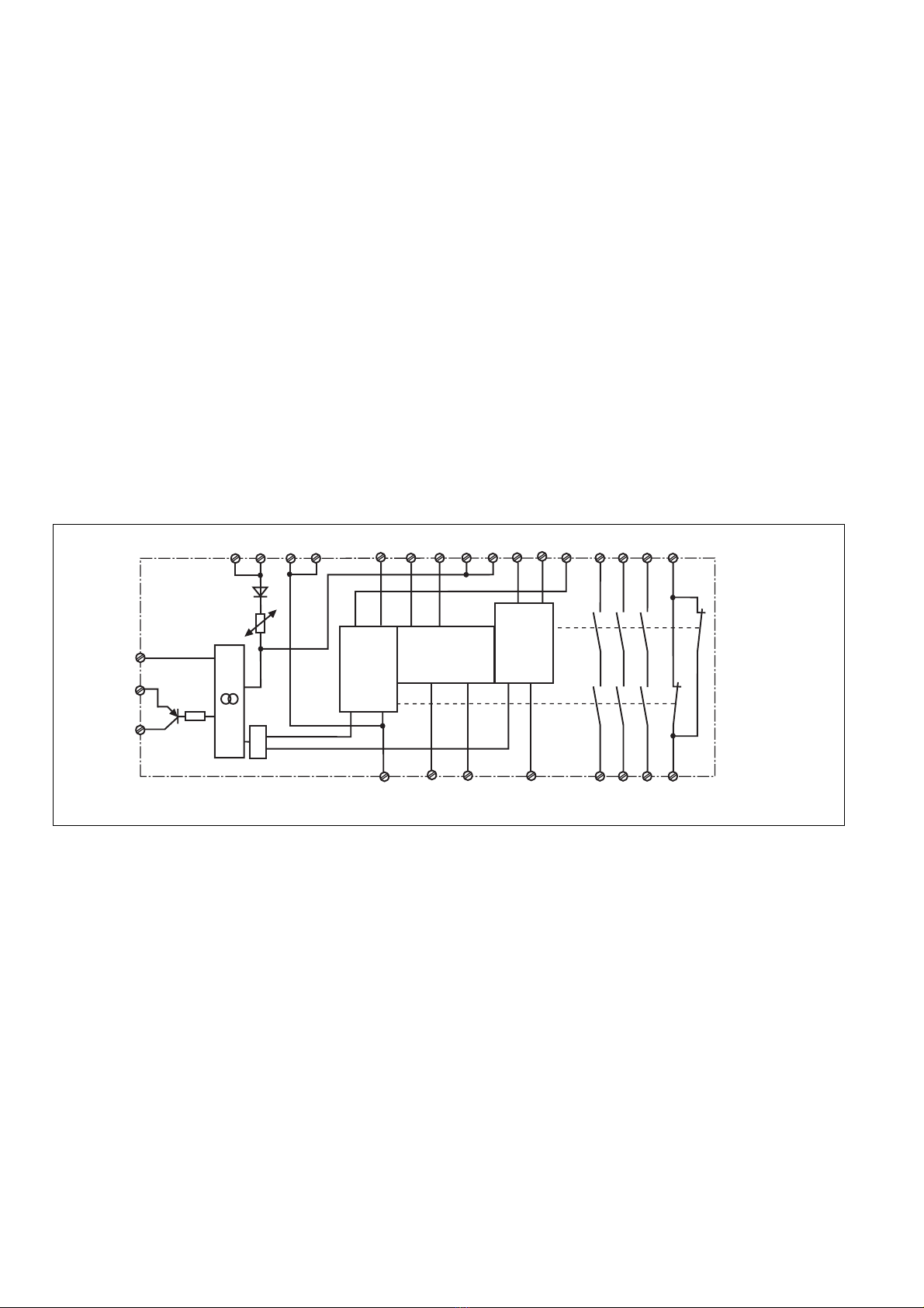
• Kontaktvervielfachung und -verstärkung
durch Anschluss von externen Schützen
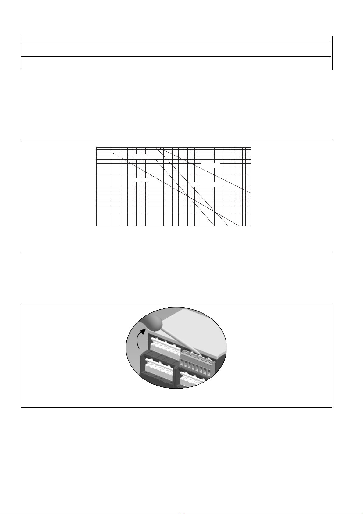
Montage
Das Sicherheitsschaltgerät muss in einen
Schaltschrank mit einer Schutzart von mind.
IP54 eingebaut werden. Zur Befestigung auf
einer Normschiene dient ein Rastelement
auf der Rückseite des Geräts.
Inbetriebnahme
Beachten Sie bei der Inbetriebnahme:
• Auslieferungszustand bei Geräten mit
Schraubklemmen: Brücke zwischen S11-
S12 (Eingangskreis zweikanalig) und
S15-S16 (Schutztürsteuerung).
• Nur die Ausgangskontakte 13-14/23-24/
33-34 sind Sicherheitskontakte. Aus-
gangskontakt 41-42 ist ein Hilfskontakt
(z. B. für Anzeige).
•Vor die Ausgangskontakte eine
Sicherung (10 A flink oder 6 A träge)
schalten, um das Verschweißen der
Kontakte zu verhindern.
• Berechnung der max. Leitungslänge Imax im
Eingangskreis:
R
lmax
R
l
/ km
I
max
=
Rlmax = max. Gesamtleitungswiderstand
(s. technische Daten)
Rl/km = Leitungswiderstand/km
Da die Funktion Querschlusserkennung
nicht einfehlersicher ist, wird sie von Pilz
während der Endkontrolle geprüft. Eine
Überprüfung nach der Installation des
Geräts ist wie folgt möglich:
1. Gerät betriebsbereit (Ausgangs-
kontakte geschlossen)
2. Die Testklemmen S22-S32 zur
Querschlussprüfung kurzschließen.
3. Die Sicherung im Gerät muss auslösen
und die Ausgangskontakte öffnen.
Leitungslängen in der Größenordnung
der Maximallänge können das Auslö-
sen der Sicherung um bis zu 2 Minuten
verzögern.
4. Sicherung wieder zurücksetzen: den
Kurzschluss entfernen und die Be-
triebsspannung für ca. 1 Minute
abschalten.
• Leitungsmaterial aus Kupferdraht mit
einer Temperaturbeständigkeit von
60/75 °C verwenden.
• Angaben im Kapitel „Technische Daten“
unbedingt einhalten.
Ablauf:
• Versorgungsspannung:
Versorgungsspannung an Klemmen A1
und A2 anlegen.
• Startkreis:
- Automatischer Start : S13-S14 brücken
(S33-S34 offen).
- Automatischer Start bei Schutztür-
steuerung: S15-S16 brücken,
Schließerkontakt der Schutztür
zwischen S13-S14 anschließen.
- Manueller Start: Taster an S33-S34
anschließen (S15-S16 offen)
- Manueller Start mit Überwachung:
Taster an S33-S34 anschließen (S13-
S14 offen).
• Eingangskreis:
- Einkanalig: S21-S22 und S31-S32
brücken. Öffnerkontakt von Auslöse-
element an S11 und S12 anschließen.
• Augmentation du nombre de contacts ou
du pouvoir de coupure par l’utilisation de
contacteurs externes.
Montage
Le relais doit être monté en armoire ayant
un indice de protection mini IP54. Sa face
arrière permet un montage sur rail DIN.
Mise en oeuvre
Remarques préliminaires :
• Pontages présents à la livraison au
appareil avec bornes à vis : S11-S12
(commande par 2 canaux) et S15-S15
(Surveillance du protecteur mobile)
• Seuls les contacts 13-14, 23-24, 33-34
sont des contacts de sécurité. Le contact
41-42 est un contact d’information (ex.
voyant)
•Protection de contacts de sortie par
des fusibles 10 A rapides ou 6 A
normaux pour éviter leur soudage
• Calcular les longueurs de câblage max
Imax dans le circuit d’entrée:
R
lmax
R
l
/ km
I
max
=
Rlmax = résistivité de câblage totale max.
(voir les caractéristiques techniques)
Rl/km = résistivité de câblage/km
La fonction de détection de court-circuit
est testé par Pilz lors du contrôle final. Un
test sur site est possible de la façon
suivante :
1. Appareil en fonction (contacts de sortie
fermés)
2. Court-circuiter les bornes de
raccordement nécessaires au test S22-
S32.
3. Le fusible interne du relais doit
déclencher et les contacts de sortie
doivent s‘ouvrir. Le temps de réponse
du fuisible peut aller jusqu‘à 2 min. si
les longueurs de câblage sont proches
des valeurs maximales.
4. Réarmement du fusible : enlever le
court-circuit et couper l‘alimentation du
relais pendant au moins 1 min.
• Utiliser uniquement des fils de cablâge en
cuivre 60/75 °C.
• Respecter les données indiquées dans le
chap. „Caractéristiques techniques“.
Mise en oeuvre :
• Tension d’alimentation :
amener la tension d’alimentation sur A1
et A2.
• Circuit de réarmement:
- réarmement automatique: pontage des
bornes S13-S14 (S33-S34 ouvert)
- réarmement automatique pour
surveillance de protecteurs mobiles :
pontage des bornes S15-S16,
protecteur mobile (contact de trevail)
sur S13-S14
- réarmement manuel : câblage d'un
poussoir sur S33-S34 (S15-S16
ouvert).
- réarmement manuel auto-côntrolé:
câblage d'un poussoir sur S33-S34
(S13-S14 ouvert).
• Circuits d’entrée:
- Commande par 1 canal : câblage du
contact à ouverture entre S11-S12,
pontage entre S21-S22 et S31-S32
• Increase in the number of available
contacts by connection of external
contactors/relays.
Installation
The safety relay must be panel mounted
(min. IP54). There is a notch on the rear of
the unit for DIN-Rail attachment.
Operation
Please note for operation:
• Unit equipped with screw terminals is
delivered with a bridge between S11-S12
(2-channel input circuit) and S15-S16
(Safety-gate control)
• Only the output contacts 13-14/23-24/33-
34 are safety contacts. Output contact
41-42 is an auxiliary contact (e.g. for a
display).
•To prevent a welding together of the
contacts, a fuse (10 A quick/6 A slow
acting) must be connected before the
output contacts.
• Calculate the max. Cable runs Imax in the
input circuit:
R
lmax
R
l
/ km
I
max
=
Rlmax = Max. Total cable resistance
(see technical details)
Rl/km = Cable resistance/km
As the function for detecting shorts across
the inputs is not failsafe, it is tested by
Pilz during the final control check.
However, a test is possible after installing
the unit and it can be carried out as
follows:
1. Unit ready for operation (output
contacts closed)
2. Short circuit the test (connection)
terminals S22-S32 for detecting shorts
across the inputs.
3. The unit‘s fuse must be triggered and
the output contacts must open. Cable
lengths in the scale of the maximum
length can delay the fuse triggering for
up to 2 minutes.
4. Reset the fuse: remove the short circuit
and switch off the operating voltage for
approx. 1 minute.
• Use copper wiring that will withstand
60/75 °C.
• Important details in the section "Technical
Data“ should be noted and adhered to.
To operate:
• Supply operating voltage:
Connect the operating voltage to
terminals A1 and A2.
• Reset circuit:
- Automatic reset: Bridge S13-S14 (S33-
S34 open).
- Automatic reset for safety-gate control:
Bridge S15-S16, connect safety gate
(N/O contact) to S13-S14
- Manual reset: Connect button to S33-
S34 (S15-S16 open).
- Manual reset with monitoring: Connect
button to S33-S34 (S13-S14 open).
• Input circuit:
- Single-channel: Bridge S21-S22 and
S31-S32. Connect N/C contact from
safety switch (e.g. Emergency-Stop) to
S12 and S11.

- 4 -
- Zweikanalig ohne Querschluss-
erkennung: S21-S22 brücken. Öffner-
kontakt von Auslöselement an S11-S12
und S11-S32 anschließen.
- Zweikanalig mit Querschluss-
erkennung: S11-S12 brücken. Öffner-
kontakt von Auslöseelement an S21-
S22 und S31-S32 anschließen.
•
Rückführkreis:
Externe Schütze in Reihe zu Startkreis
S13-S14 bzw. S33-S34 anschließen.
• 24 V Versorgungsspannung für
Halbleiterausgang: +24 V DC an Klemme
Y31 und 0 V an Klemme Y30 anschlie-
ßen.
Die Sicherheitskontakte sind aktiviert (ge-
schlossen) und der Hilfskontakt 41-42 ist
geöffnet. Die Statusanzeige für "CH.1",
"CH. 2", leuchten. Das Gerät ist betriebsbe-
reit. Wird der Eingangskreis geöffnet, öffnen
die Sicherheitskontakte 13-14/23-24/33-34
und der Hilfskontakt 41-42 schließt. Die
Statusanzeige erlischt.
Wieder aktivieren
• Eingangskreis schließen.
• Bei manuellem Start Taster zwischen S13
und S14 betätigen.
• Bei manuellem Start mit Überwachung
Taster zwischen S33 und S34 betätigen.
Die Statusanzeigen leuchten wieder, die
Sicherheitskontakte sind geschlossen.
- Commande par 2 canaux sans détection
de courts-circuits : câblage du contact à
ouverture entre S11-S12 et S11-S32,
pontage entre S21-S22
- Commande par 2 canaux avec détection
de courts-circuits : câblage des contacts
à ouverture entre S21-S22 et S31-S32,
pontage entre S11-S12
• Boucle de retour:
câbler les contacts des contacteurs
externes en série dans le circuit de
réarmement S13-S14 ou S33-S34
• Alimentation en 24 VCC de sortie
statique: relier le +24 V DC à la borne
Y31 et le 0 V à la borne Y30.
Les contacts de sécurité se ferment et le
contact d’information 41-42 s’ouvre. Les
LEDs "CH.1"et "CH.2" sont allumées.
L’appareil est prêt à fonctionner.
Si le circuit d’entrée est ouvert, les contacts
de sécurité retombent et le contact
d’information 41-42 se ferme. Les LEDs
s’éteignent.
Remise en route :
• fermer le circuit d’entrée.
• en cas de réarement manuel, appuyer le
poussoir S13-S14.
• en cas de surveillance du circuit de
réarmement, appuyer le poussoir de
validation S33-S34.
Les affichages d'état s'allument à nouveau.
Les contacts de sécurité sont fermées.
Utilisation
Les figures 2 à 11 représentent les
différents câblages possibles du PNOZ X3P
à savoir : poussoir AU avec réarmement
automatique ou auto-côntrolé, interrupteurs
de position, barrage immatériel et
augmentation du nombre des contacts de
sécurité par contacteurs externes.
• Fig. 2 et 7: pas de câblage sur S33-S34
• Fig. 3, 4 et 5, 6:
pas de câblage sur S13-S14
• Fig. 7: Réarmement automatique en cas
de surveillance protecteur: lorsque le
protecteur est ouvert, le circuit S13-S14
se ferme et le relais est prêt à fonction-
ner. Dès la fermeture des canaux
d'entrée S21-S22 et S31-S32, les
contacts de sortie du relais se ferment.
Dans le cas de la figure 2 et 7, l’appareil se
réarme automatiquement après une
coupure et une remise sous tension. Evitez
tout risque de redémarrage par un câblage
externe approprié.
- Two-channel without detection of shorts
across the contacts: Bridge S21-S22.
Connect N/C contact from safety switch
to S11-S12 and S31-S32.
- Two-channel with detection of shorts
across the contacts: Bridge S11-S12.
Connect N/C contact from safety switch
to S21-S22 and S31-S32.
• Feedback control loop:
Connect external relays/contactors in
series to reset circuit S13-S14 or S33-
S34.
• 24 VDC supply voltage for semi-
conductor output: Connect +24 VDC to
terminals Y31 and 0 VDC to Y30.
The safety contacts are activated (closed)
and the auxiliary contact (41-42) is open.
The status indicators "CH.1"and "CH.2" are
illuminated. The unit is ready for operation.
If the input circuit is opened, the safety
contacts 13-14/23-24, 33-34 open and the
auxiliary contact 41-42 closes. The status
indicator goes out.
Reactivation
• Close the input circuit.
• For manual reset, press the button
between S13 and S14.
• For manual reset with monitoring, press
the button between S33-S34.
The status indicators light up again, the
safety contacts are closed.
Anwendung
Fig. 2 ... Fig. 11 zeigen Anschlussbeispiele
für Not-Halt-Beschaltung mit automatischem
und überwachtem Start, Schutztüran-
steuerung und Lichtschrankensteuerung
sowie Kontaktvervielfachung durch externe
Schütze.
Bitte beachten Sie:
• Fig. 2 und 7: keine Verbindung S33-S34
• Fig. 3, 4 und 5, 6: keine Verbindung S13-
S14
• Fig. 7: Automatischer Start bei Schutztür-
steuerung: Das Gerät ist bei geöffneter
Schutztür über den Startkreis S13-S14
startbereit. Nach Schließen der Eingangs-
kreise S21-S22 und S31-S32 werden die
Sicherheitskontakte geschlossen.
Beachten Sie bei Fig. 2 und 7: Das Gerät
startet bei Spannungsausfall und
-wiederkehr automatisch. Verhindern Sie
einen unerwarteten Wiederanlauf durch
externe Schaltungsmaßnahmen.
Application
Fig. 2 ...Fig. 11 show connection examples
for Emergency Stop wiring with automatic
and monitored reset, safety gate control and
light curtain control as well as contact
expansion via external contactors.
• Fig. 2 and 7: S33-S34 not connected
• Fig. 3, 4 and 5, 6: S13-S14 not connected
• Fig. 7: Automatic reset with safety gate
control: with the safety gate open the unit
is ready for operation via reset circuit
S13-S14. After closing the safety input
circuit S21-S22 and S31-S32 the safety
contacts will close.
Please note for Fig. 2 and 7: the device
starts automatically after loss of power. You
should prevent an unintended start-up by
using external circuitry measures.
S21
S22 S12 S34
S32
S33
S11
S31
S1 S3
S11 S31 S13
S12 S14
S32
S21
S22
S1
S11 S31 S13
S12 S14S32
S21
S22
S1 S3
Fig.4: Eingangskreis zweikanalig, über-
wachter Start/Two-channel input circuit,
monitored reset/Commande par 2 canaux,
surveillance du poussoir de validation
Fig. 3: Eingangskreis einkanalig, manueller
Start/Single-channel input circuit, manual
reset/Commande par 1 canal, validation
manuel
Fig. 2: Eingangskreis einkanalig, automat.
Start/Single-channel input circuit, automatic
reset/Commande par 1 canal, validation
automatique

- 5 -
Erreurs - Défaillances
• Défaut de masse du PNOZ X3.10P:
un fusible électronique entraîne
l’ouverture des contacts de sortie. Une
fois la cause du défaut éliminée et la
tension d’alimentation coupée pendant
environ 1 minute, l’appareil est à nouveau
prêt à fonctionner.
• Défaut de fonctionnement des contacts
de sortie: en cas de soudage d’un contact
lors de l’ouverture du circuit d’entrée, un
nouvel réarmement est impossible.
• LED "Power" éteinte: tension
d'alimentation non présente ou court-
circuit interne.
Fehler - Störungen
• Erdschluss bei PNOZ X3.10P:
Eine elektronische Sicherung bewirkt das
Öffnen der Ausgangskontakte. Nach
Wegfall der Störungsursache und
Abschalten der Versorgungsspannung für
ca. 1 min ist das Gerät wieder betriebs-
bereit.
• Fehlfunktionen der Kontakte: Bei ver-
schweißten Kontakten ist nach Öffnen des
Eingangskreises keine neue Aktivierung
möglich.
• LED "Power" leuchtet nicht: Kurzschluss
oder Versorgungsspannung fehlt.
Faults
• Earth fault on PNOZ X3.10P:
An electronic fuse causes the output
contacts to open. Once the cause of the
fault has been removed and the supply
voltage shut off for approx. 1 min, the unit
is ready for operation.
• Contact failure: In the case of welded
contacts, no further activation is possible
following an opening of the input circuit.
• LED "Power" is not illuminated if short-
circuit or the supply voltage is lost.
Fig. 10: wie Fig. 9 mit überwachtem Start/
Like Fig. 9 with monitored reset/comme Fig.
9 avec surveillance du poussoir de
validation
Fig. 9: Anschlussbeispiel für externe
Schütze, einkanalig, automatischer Start/
Connection example for external contactors/
relays, single-channel, automatic reset/
Branchement contacteurs externes,
commande par 1 canal, validation
automatique
Fig. 11: Anschlussbeispiel für Halbleiter-
ausgang/Connection of semiconductor
output/Câblage de la sortie statique
E0.0
24V
E0.1
E0.2
E0.3
A0.0
A0.1
A0.2
A0.3
0V
SPS
Y31
Y30
A2
PNOZ X3.10P
Y32 14 24 42
34
14
K5 K6
13
S33 S34
K5
K6
1L1
1L2
S3
14
K5 K6
13
S13 S14
K5
K6
1L1
1L2
S12 S34
S33
S11
S21
S32
S22
S31
S1
S2
S3
S12
S14
S13 S11
S21
S32
S22
S1
S2
S31
S16
S15
Fig. 7: Schutztürsteuerung zweikanalig,
automatischer Start mit Anlauftest/Two
channel safety gate control, automatic reset/
Surveillance de protecteur, commande par 2
canaux, validation automatique
Fig. 6: Schutztürsteuerung zweikanalig,
überwachter Start/Two-channel safety gate
control, monitored reset/Surveillance de
protecteur, commande par 2 canaux,
surveillance du poussoir de validation
Fig. 5: Schutztürsteuerung einkanalig,
überwachter Start/Single-channel safety
gate control, monitored reset/Surveillance
de protecteur, commande par 1 canal,
surveillance du poussoir de validation
S32 S34
S33
S31
S11
S22
S12
S21
S1
S3
betätigtes Element/Switch
activated/élément actionné
Tür nicht geschlossen/Gate
open/porte ouverte
Tür geschlossen/Gate closed/
porte fermée
S1/S2: Not-Halt- bzw. Schutztürschalter/
Emergency Stop Button, Safety
Gate Limit Switch/Poussoir AU,
détecteurs de position
S3: Starttaster/Reset button/Poussoir de
réarmement
S11
S12 S22 S34S32
S33S21S31
S3
BWS 24 V DC
Fig. 8: Lichtschrankensteuerung, zwei-
kanalig, Querschlusserkennung durch BWS,
überwachter Start/Dual-channel light curtain
control, short circuit detection via ESPE,
monitored reset/Commande par 2 canaux
par barrage immatériel ,surveillance du
poussoir de validation

- 6 -
Technische Daten
Elektrische Daten
Versorgungsspannung UB
Spannungstoleranz
Leistungsaufnahme bei UB
Frequenzbereich AC
Restwelligkeit
Spannung und Strom an
Eingangskreis
Startkreis
Rückführkreis
Anzahl der Ausgangskontakte
Sicherheitskontakte (S)
Hilfskontakte (Ö)
Gebrauchskategorie nach
EN 60947-4-1
EN 60947-5-1(DC13:
6 Schaltspiele/Min.)
Kontaktmaterial
Kontaktabsicherung extern
EN 60947-5-1 (IK= 1 kA)
Schmelzsicherung flink
Schmelzsicherung träge
Sicherungsautomat
Charakteristik
Halbleiterausgänge (kurzschlussfest)
Externe Spannungsversorgung
Max. Gesamtleitungswiderstand Rlmax
Eingangskreise
einkanalig DC
einkanalig AC
zweikanalig ohne
Querschlusserkennung DC
zweikanalig ohne
Querschlusserkennung AC
zweikanalig mit
Querschlusserkennung DC
zweikanalig mit
Querschlusserkennung AC
Sicherheitstechnische Kenndaten
der Sicherheitsausgänge
PL nach EN ISO 13849-1
Kategorie nach EN 954-1
SIL CL nach EN IEC 62061
PFH nach EN IEC 62061
SIL nach IEC 61511
PFD nach IEC 61511
tMin Jahren
Zeiten
Einschaltverzögerung
automatischer Start
automatischer Start nach Netz-Ein
manueller Start
überwachter Start
Rückfallverzögerung
bei Not-Halt
bei Netzausfall
Wiederbereitschaftszeit bei max.
Schaltfrequenz 1/s
nach Not-Halt
nach Netzausfall
Wartezeit bei überwachtem Start
24 V AC/DC
-15 ... +10 %
AC: 5,0 VA
DC: 2,5 W
50 ... 60 Hz
DC: 160 %
24 V DC: 40 mA
24 V DC: 70 mA
24 V DC: 20 mA
3
1
AC1: 240 V/0,01 ... 8 A/
2000 VA
DC1: 24 V/0,01 ... 8 A/
200 W
AC15: 230 V/5 A;
DC13: 24 V/6 A
AgSnO2+ 0,2 µm Au
10 A
6 A
24 V AC/DC: 6 A
B/C
24 V DC/20 mA
24 V DC, ± 20%
150 Ohm
180 Ohm
300 Ohm
360 Ohm
15 Ohm
30 Ohm
PL e (Cat. 4)
Cat. 4
SIL CL 3
2,31E-09
SIL 3
2,03E-06
20
typ. 250 ms, max. 500 ms
typ. 280 ms, max. 550 ms
typ. 200 ms, max. 500 ms
typ. 35 ms, max. 50 ms
typ. 15 ms, max. 30 ms
typ. 180 ms, max. 260 ms
50 ms
350 ms
300 ms
Technical Data
Electrical data
Supply Voltage UB
Voltage Tolerance
Power consumption at UB
Frequency range
Residual Ripple
Voltage and Current at
Input circuit
Reset circuit
Feedback loop
Number of output contacts
Safety contacts (N/O)
Auxiliary contacts (N/C)
Utilization category in accordance with
EN 60947-4-1
EN 60947-5-1(DC13: 6 cycles/min)
Contact material
External contact fuse protection
EN 60947-5-1 (IK= 1 kA)
Blow-out fuse quick
Blow-out fuse slow
Safety cut-out
Cvaracteristic
Semiconductor outputs (short circuit
proof)
External voltage supply
Max. overall cable resistance Rlmax
input circuits
single-channel DC
single-channel AC
dual-channel without detection of
shorts across contacts DC
dual-channel without detection of
shorts across contacts AC
dual-channel with detection of
shorts across contacts DC
dual-channel with detection of
shorts across contacts AC
Safety-related characteristics of
the safety outputs
PL in accordance with
EN ISO 13849-1
Category in accordance with
EN 954-1
SIL CL in accordance with
EN IEC 62061
PFH in accordance with
EN IEC 62061
SIL in accordance with IEC 61511
PFD in accordance with IEC 61511
tM in years
Times
Switch-on delay
automatic reset
automatic reset after power-ON
manual reset
monitored reset
Delay-on De-Energisation
at E-STOP
with power failure
Recovery time at max. switching
frequency 1/s
after E-STOP
after power failure
Waiting period at monitored reset
Caractéristiques techniques
Données électriques
Tension d’alimentation UB
Plage de la tension d’alimentation
Consommation pour UB
Fréquence
Ondulation résiduelle
Tension et courant du
Circuit d’entrée
Circuit de réarmement
Circuit de boucle de retour
Nombre de contacts de sortie
contacts de sécurité (F)
contact d'info (O)
Catégorie d’utilisation selon
EN 60947-4-1
EN 60947-5-1(DC13:
6 manoeuvres/min)
Matériau contact
Protection des contacts externe
EN 60947-5-1 (IK= 1 kA)
Fusibles rapide
Fusibles normal
Dijoncteur
Caractéristique
Sorties statiques (protégées
contre c.c.)
Alimentation externe
Résistance de câblage totale max.
Rlmax circuits d'entrée
commande par 1 canal DC
commande par 2 canaux sans
détection des courts-circuit DC
commande par 2 canaux sans
détection des courts-circuit AC
commande par 2 canaux avec
détection des courts-circuit DC
commande par 2 canaux avec
détection des courts-circuit AC
Caractéristiques techniques de
sécurité des sorties de sécurité
PL selon EN ISO 13849-1
Catégorie selon EN 954-1
SIL CL selon EN IEC 62061
PFH selon EN IEC 62061
SIL selon IEC 61511
PFD selon IEC 61511
tM en années
Temporisations
Temps de réarmement
réarmement automatique
réarmement automatique après
mise sous tension
réarmement manuel
réarmement auto-contrôlé
Temps de retombée
en cas d'arrêt d'urgence
en cas de coupure d'alimentation
Temps de remise en service en cas de
fréquence de commutation max. 1/s
arrêt d'urgence
après une coupure d'alimentation
Durée dattente au réarmement auto-
contrôlé

- 7 -
Min. Startimpulsdauer bei
überwachtem Start
Gleichzeitigkeit Kanal 1 und 2
Überbrückung bei
Spannungseinbrüchen
Umweltdaten
EMV
Schwingungen nach EN 60068-2-6
Frequenz
Amplitude
Klimabeanspruchung
Luft- und Kriechstrecken nach
EN 60947-1
Verschmutzungsgrad
Überspannungskategorie
Bemessungsisolationsspannung
Bemessungsstoßspannungsfestigkeit
Umgebungstemperatur
Lagertemperatur
Schutzart
Einbauraum (z. B. Schaltschrank)
Gehäuse
Klemmenbereich
Mechanische Daten
Gehäusematerial
Gehäuse
Front
Querschnitt des Außenleiters
(Schraubklemmen)
1 Leiter, flexibel
2 Leiter gleichen Querschnitts, flexi-
bel mit Aderendhülse, ohne
Kunststoffhülse
ohne Aderendhülse oder mit TWIN-
Aderendhülse
Querschnitt des Außenleiters
(Federkraftklemmen)
flexibel ohne Aderendhülse
Gehäuse mit Federkraftklemmen
Abisolierlänge
Klemmstellen pro Anschluss
Anzugsdrehmoment für
Schraubklemmen
Abmessungen (Schraubklemmen)
H x B x T
Abmessungen (Federkraftklemmen)
H x B x T
Einbaulage
Gewicht
Min. start pulse duration with a
monitored reset
Simultaneity channel 1 and 2
Supply interruption before de-
energisation
Environmental data
EMC
Vibration to EN 60068-2-6
Frequency
Amplitude
Climate Suitability
Airgap Creepage in accordance with
EN 60947-1
Pollution degree
Overvoltage category
Rated insulation voltage
Rated impulse withstand voltage
Ambient temperature
Storage temperature
Protection type
Mounting (eg. panel)
Housing
Terminals
Mechanical data
Housing material
Housing
Front panel
Cable cross section (screw
terminals)
1 core, flexible
2 core, same cross section flexible
with crimp connectors, without
insulating sleeve
without crimp connectors or with
TWIN crimp connectors
Cable cross section (spring-loaded
terminals)
flexible without crimp connectors
Housing with spring-loaded terminals
Stripping length
Termination points per connection
Torque setting for screw terminals
Dimensions (screw terminals)
H x W x D
Dimensions (spring-loaded terminals)
H x W x D
Fitting Position
Weight
Durée minimale de l'impulsion pour
un réarmement auto-contrôlé
Désynchronisme canal 1 et 2
Tenue aux micro-coupures
Données sur l'environnement
CEM
Vibrations selon EN 60068-2-6
Frequence
Amplitude
Conditions climatiques
Cheminement et claquage selon
EN 60947-1
Niveau d'encrassement
Catégorie de surtensions
Tension assignée d'isolement
Tension assignée de tenue aux chocs
Température d’utilisation
Température de stockage
Indice de protection
Lieu d'implantation (ex. armoire)
Boîtier
Bornes
Données mécaniques
Matériau du boîtier
Boîtier
Face avant
Capacité de raccordement
(borniers à vis)
1 conducteur souple
2 conducteurs de même diamètre
souple avec embout, sans chapeau
plastique
souple sans embout ou avec
embout TWIN
Capacité de raccordement (borniers
à ressort)
souple sans embout
Boîtier avec borniers à ressort
Longueur de dénudage
Bornes par raccordement
Couple de serrage (borniers à vis)
Dimensions (borniers à vis)
H x P x L
Dimensions (borniers à ressort)
H x L x P
Position de travail
Poids
30 ms
∞
150 ms
EN 60947-5-1,
EN 61000-6-2
10 ... 55 Hz
0,35 mm
EN 60068-2-78
2
III
250 V
4 kV
-20 ... + 55 °C
-40 ... +85 °C
IP54
IP40
IP20
PPO UL 94 V0
ABS UL 94 V0
0,25 ... 2,5 mm2, 24 - 12 AWG
0,25 ... 1 mm2, 24 - 16 AWG
0,20 ... 1,5 mm2, 24 - 16 AWG
8 mm
2
0,5 Nm
94 x 45 x 121 mm
101 x 45 x 121 mm
beliebig/any/indifférente
280 g
Es gelten die 2007-09 aktuellen Ausgaben
der Normen
The version of the standards current at
2007-09 shall apply
Se référer à la version des normes en
vigeur au 2007-09.

- 8 -
Konventioneller thermischer Strom bei gleichzeitiger Belastung mehrerer Kontakte/Conventional thermal current
while loading several contacts/Courant thermique conventionnel en cas de charge sur plusieurs contacts (AC1, DC1)
Anzahl der Kontakte/number of contacts/nombre des contacts 3 2 1
Ith (A) pro Kontakt bei Versorgungsspannung DC/per contact with operating voltage DC/
par contact pour tension d'alimentation DC 7,0 8,0 8,0
Ith (A) pro Kontakt bei Versorgungsspannung AC/per contact with operating voltage AC/
par contact pour tension d'alimentation AC 6,0 7,0 8,0
Um ein Versagen der Geräte zu verhindern,
an allen Ausgangskontakten für eine aus-
reichende Funkenlöschung sorgen. Bei
kapazitiven Lasten sind eventuell auftretende
Stromspitzen zu beachten. Bei DC-Schützen
Freilaufdioden zur Funkenlöschung einsetzen,
um die Lebendauer der Schütze zu erhöhen.
To prevent failure of the unit, all output
contacts should be fused adequately. With
capacative loads, possible current peaks are
to be avoided. With DC contactors/relays
use suitable spark suppression to ensure
extended life of the contactors/relays.
Prévoir un dispositif d’extinction d’arc sur les
contacts de sortie pour éviter un éventuel
disfonctionnement du relais.
Tenir compte des pointes d’intensité en cas
de charge capacitive. Equiper les
contacteurs DC de diodes de roue libre .
Steckbare Klemmen abziehen
Schraubendreher in Gehäuseaussparung
hinter der Klemme ansetzen und Klemme
heraushebeln.
Klemmen nicht an den Kabeln abziehen!
Abziehen der Klemmen am Beispiel einer
Schraubklemme
Remove plug-in terminals
Insert screwdriver into the cut-out of the
housing behind the terminal and lever the
terminal.
Do not remove the terminals by pulling the
cables!
How to remove the terminals using a screw
terminal as an example
Démonter les borniers débrochables
Placer un tournevis derrière les bornes et
sortir le bornier.
Ne pas retirer les borniers en tirant sur les
câbles !
Démontage d’un bornier à vis
Lebensdauer der Ausgangsrelais/Service Life of Output relays/Durée de vie des relais de sortie
10
1
10 100 1000 10000
Nennbetriebstrom (A)
Nominal operating current (A)
Courant coupé (A)
0.1
DC13: 24 V
AC15: 230 V
AC1: 230 V
DC1: 24 V
Schaltspielzahl x 103
C cles x 103
Nombre de manvres x 103

- 9 -
Abmessungen in mm/Dimensions in mm/Dimensions en mm
75 (2.95")
94 (3.70")
121 (4.76")
45
(1.77")
87 (3.42")
45
(1.77")
75 (2.95")
101 (3.98")
121 (4.76")
87 (3.42")
Gehäuse mit steckbaren Schraubklemmen/
Housing with plug-in screw terminals/
Boîtier avec borniers débrochables à vis
Gehäuse mit steckbaren Federkraftklemmen/
Housing with plug-in spring-loaded terminals/
Boîtier avec borniers débrochables à ressort/
EG-Konformitätserklärung:
Diese(s) Produkt(e) erfüllen die Anforderun-
gen der Richtlinie 2006/42/EG über
Maschinen des europäischen Parlaments
und des Rates.
Die vollständige EG-Konformitätserklärung
finden Sie im Internet unter www.pilz.com
Bevollmächtigter: Norbert Fröhlich,
Pilz GmbH & Co. KG, Felix-Wankel-Str. 2,
73760 Ostfildern, Deutschland
EC Declaration of Conformity:
This (these) product(s) comply with the
requirements of Directive 2006/42/EC of the
European Parliament and of the Council on
machinery.
The complete EC Declaration of Conformity
is available on the Internet at www.pilz.com
Authorised representative: Norbert Fröhlich,
Pilz GmbH & Co. KG, Felix-Wankel-Str. 2,
73760 Ostfildern, Germany
Déclaration de conformité CE :
Ce(s) produit(s) satisfait (satisfont) aux
exigences de la directive 2006/42/CE
relative aux machines du Parlement
Européen et du Conseil.
Vous trouverez la déclaration de conformité
CE complète sur notre site internet
www.pilz.com
Représentant : Norbert Fröhlich,
Pilz GmbH & Co. KG, Felix-Wankel-Str. 2,
73760 Ostfildern, Allemagne

- 10 -
A
AUS
Pilz Australia, ✆03 95446300, Fax: 03 95446311, E-Mail:
B L
BR
Pilz do Brasil, ✆11 4337-1241, Fax: 11 4337-1242,
E-Mail: pilz@pilzbr.com.br
CH
DK
Pilz Skandinavien K/S,
✆74436332, Fax: 74436342, E-Mail: [email protected]
E
F
Pilz France
FIN
Pilz Skandinavien K/S, ✆09 27093700, Fax: 09 27093709, E-Mail:
pilz.f[email protected]
GB
I
Pilz ltalia Srl, ✆031 789511,
IRL
J
Pilz Japan Co.,
MEX
Pilz de Mexico, S. de R.L. de C.V., ✆55 5572 1300, Fax: 55 5572 4194, E-Mail:
NL
NZ
Pilz New Zealand, ✆09- 6345-350, Fax: 09-6345-
P
PRC
Pilz China Representative
Office, ✆021 62494658, Fax: 021 62491300,
ROK
Pilz Korea, ✆031 8159541, Fax: 031 8159542, E-Mail: info@pilzkorea.co.kr
SE
TR
Pilz Elektronik Güvenlik Ürünleri ve Hizmetleri Tic. Ltd. ¸Sti.,
✆0224 2360180, Fax: 0224 2360184, E-Mail: [email protected]
USA
Pilz Automation Safety L.P., ✆734 354-0272, Fax: 734 354-3355, E-Mail:
www
www.pilz.com
D
Pilz GmbH & Co. KG, Sichere Automation, Felix-Wankel-Straße 2, 73760 Ostfildern, Deutschland, ✆+49 711 3409-0, Fax: +49 711 3409-133,
E-Mail: [email protected]
Originalbetriebsanleitung/Original instructions/Notice originale
20 874-02, 2009-11 Printed in Germany

- 11 -
Norme di sicurezza
• Il dispositivo deve essere installato e
messo in funzione solo da persone a
conoscenza delle presenti istruzioni per
l’uso e delle norme antinfortunistiche e di
sicurezza del lavoro vigenti.
• Si devono inoltre rispettare le norme
VDE, nonché le norme locali, soprattutto
per quanto riguarda gli interventi di
sicurezza.
• Per il trasporto, l’immagazzinamento ed il
funzionamento, rispettare le norme
EN 60068-2-78 (vedere i dati tecnici).
• In caso di apertura della custodia o di
modifiche non autorizzate, non sarà
riconosciuta alcuna garanzia.
• Montare il dispositivo in un armadio
elettrico, perché la polvere e l’umidità
potrebbero comprometterne il
funzionamento.
• In caso di carichi capacitivi ed induttivi,
assicurareuna adeguata protezione per
tutti i contatti di uscita.
Uso previsto
Il modulo di sicurezza consente
I'interruzione sicura di un circuito di
sicurezza. Il modulo di sicurezza risponde ai
requisiti secondo EN 60947-5-1, EN 60204-
1 e VDE 0113-1 e può essere utilizzato in
applicazioni con
• pulsanti di arresto d'emergenza
• ripari mobili
• barriere fotoelettriche
Descrizione del dispositivo
Il dispsositivo di sicurezza PNOZ X3.10P è
inserito in una custodia P-99. Il dispositivo
può funzionare con tensione continua di
24 V, oppure con tensione alternata di 24 V.
Caratteristiche:
• Uscite relè: 3 contatti di sicurezza (NA) ed
un contatto ausiliario (contatto NC), a
conduzione forzata
• Possibilità di collegamento per pulsanti di
arresto di emergenza, finecorsa riparo
mobile e pulsante di start
• LED di stato
• Possibilità di controllo dei relè esterni
• L’uscita a semiconduttore segnala il
funzionamento
Il dispositivo elettrico è conforme ai seguenti
requisiti di sicurezza:
• Concezione ridondante con autocontrollo
(EN 954-1, categoria 4).
• Il dispositivo mantiene la sua funzione di
sicurezza anche in caso di avaria di un
componente.
• Ad ogni ciclo di inserimento-disinseri-
mento della macchina, viene controllato
automaticamente se i relè del dispositivo
di sicurezza aprono e chiudono corretta-
mente.
• Il dispositivo è dotato di un fusibile
elettronico.
Normas de seguridad
• El dispositivo debe ser instalado y puesto
en funcionamiento sólo por personas que
tengan experiencia con estas
instrucciones de uso y con las normativas
de seguridad del trabajo y prevención de
accidentes vigentes.
• Tenga en cuenta las normativas VDE,
como también las normativas locales,
especialmente en lo concerniente a
medidas de protección.
• Respetar las exigencias de la norma
EN 60068-2-78 referente al transporte,
almacenaje y utilización del dispositivo (v.
datos técnicos).
• Por apertura de la carcasa o
modificaciones arbitrarias, caduca
cualquier tipo de garantía.
• Instale el dispositivo en un armario de
distribución; polvo y humedad pueden
conducir, de lo contrario, a una merma de
las funciones.
• Procúrese una conexión de protección
adecuada, en todos los contactos de
salida sometidos a cargas capacitivas e
inductivas.
Aplicación correcta
El dispositivo sirve para la interrupción
orientada a la seguridad de un circuito de
corriente de seguridad. El dispositivo de
seguridad cumple los requisitos de las
normas EN 60947-5-1, EN 60204-1 y
VDE 0113-1 y puede utilizarse en
aplicaciones con
• pulsadores de parada de emergencia
• puertas protectoras
• barreras fotoeléctricas
Descripción del dispositivo
El dispositivo de seguridad PNOZ X3.10P
está alojado en una carcasa P-99. Se
puede hacer funcionar con tensión de
corriente contínua o alterna de 24 V.
Características:
• Salidas de relés: 3 contactos de
seguridad (normalmente abierto) y un
contacto auxiliar (normalmente cerrado),
de guía forzosa
• Opción de conexión para pulsador de
parada de emergencia, final de carrera de
seguridad de puerta protectora y pulsador
de rearme
• Indicadores de estado
• Posibilidad de supervisión de contactores
externos
• La salida de semiconductor comunica
disposición para el funcionamiento
El dispositivo cumple los siguientes
requisitos de seguridad:
• Concepción redundante con autosuper-
visión (EN 954-1, categoría 4).
• El dispositivo de seguridad permanece
activo aún cuando falle un componente.
• En cada ciclo de marcha/parada de la
máquina, se verifica automáticamente, si
los relés del dispositivo de seguridad
abren y cierran correctamente.
• El dispositivo tiene un fusible electrónico.
Veiligheidsvoorschriften
• Het apparaat mag uitsluitend worden
geïnstalleerd en in bedrijf genomen door
personen die vertrouwd zijn met deze
gebruiksaanwijzing en met de geldende
voorschriften op het gebied van
arbeidsveiligheid en ongevallenpreventie.
• Neemt u de van toepassing zijnde
Europese richtlijnen en de plaatselijke
voorschriften in acht, in het bijzonder
m.b.t. veiligheidsmaatregelen.
• Neemt u bij transport, opslag en in bedrijf
de richtlijnen volgens EN 60068-2-78 in
acht (zie technische gegevens).
• Het openen van de behuizing of het
eigenmachtig veranderen van de
schakeling heeft verlies van de garantie
tot gevolg.
• Monteert u het apparaat in een
schakelkast. Stof en vochtigheid kunnen
anders de werking nadelig beïnvloeden.
• Zorgt u bij capacitieve of inductieve
belasting van de uitgangscontacten voor
adequate contactbeschermings-
maatregelen.
Toegelaten applicaties
Het veiligheidsrelais dient om een
veiligheidscircuit veilig te onderbreken. Het
veiligheidsrelais voldoet aan de eisen van
EN 60947-5-1, EN 60204-1 en VDE 0113-1
en mag worden gebruikt in toepassingen
met
• noodstopknoppen
• hekken
• lichtschermen
Apparaatbeschrijving
Het veiligheidsrelais PNOZ X3.10P is in een
P-99-behuizing ondergebracht. Het kan met
24 V gelijkspanning of wisselspanning
gebruikt worden.
Kenmerken:
• Relaisuitgangen: 3 veiligheidscontacten
(maakcontacten) en 1 hulpcontact
(verbreekcontact), mechanisch
gedwongen
• Aansluitmogelijkheid voor noodstop-
knoppen, deurcontacten en de startknop
• Status-LED’s
• Bewaking van externe magneet-
schakelaars mogelijk
• Halfgeleideruitgang geeft melding indien
bedrijfsklaar
Het relais voldoet aan de volgende
veiligheidseisen:
• De schakeling is redundant met
zelfcontrole opgebouwd (EN 954-1
categorie 4).
• Ook bij uitvallen van een component blijft
de veiligheidsschakeling werken.
• Bij elke aan/uit-cyclus van de machine
wordt automatisch getest of de relais-
contacten van de veiligheidsvoorziening
correct openen en sluiten.
• Het apparaat heeft een elektronische
zekering.
20 874-02
PNOZ X3.10P
4E Instrucciones de uso
4I Istruzioni per l`uso
4NL Gebruiksaanwijzing

- 12 -
Descrizione del funzionamento
Il dispositivo elettrico PNOZ X3.10P serve
per interrompere in modo sicuro un circuito
elettrico di sicurezza. Dopo l’applicazione
della tensione di alimentazione si accende il
LED «Power». Il dispositivo è pronto per il
funzionamento dopo che è stato chiuso il
circuito start S13-S14, o dopo che un
contatto di start su S33-S34 è stato aperto e
nuovamente chiuso.
• Circuito di ingresso chiuso (per es.
pulsante di arresto di emergenza non
azionato):
i relè K1 e K2 si attivano automanten-
endosi. I LED di stato per «CH.1» e
«CH.2» sono accesi. I contatti di
sicurezza (13-14/23-24/33-34) sono
chiusi, il contatto ausiliario (41-42) è
aperto.
• Apertura del circuito di ingresso (per es.
in caso di azionamento del pulsante di
arresto di emergenza):
i relè K1 e K2 tornano nella posizione di
riposo. I LED di stato per «CH.1» e
«CH.2» si spengono. I contatti di
sicurezza (13-14/23-24/33-34) vengono
aperti in modo ridondante, il contatto
ausiliario (41-42) viene chiuso.
Uscita a semiconduttore
L’uscita a semiconduttore Y32 è conducente
quando i relè K1 e K2 sono attivati. L’uscita
blocca quando i relè sono nella posizione di
riposo.
Modalità operative
• Funzionamento monocanale: cablaggio di
ingresso secondo VDE 0113-1 e EN
60204-1; senza ridondanza nel circuito di
ingresso, le dispersioni verso terra nel
circuito del pulsante vengono rilevate.
• Funzionamento bicanale: circuito di
ingresso ridondante; vengono rilevate le
dispersioni verso terra nel circuito del
pulsante, nonché il cortocircuito trasversali
tra i contatti del pulsante stesso.
• Start automatico: Il dispositivo è attivo
non appena il circuito di ingresso è
chiuso.
• Start manuale: il dispositivo è attivo solo
dopo che è stato azionato un pulsante di
start.
• Start manuale controllato: il dispositivo è
attivo solo quando, prima della chiusura
del circuito di ingresso, il circuito di start
viene aperto, e chiuso solo dopo la
chiusura del circuito di entrata e al
termine di un tempo di pausa (v. dati
tecnici). In tal modo si esclude
un’attivazione automatica e un’esclusione
del pulsante di start.
Descripción funcional
El dispositivo PNOZ X3.10P sirve para una
interrupción por motivos de seguridad de un
circuito eléctrico de seguridad. Después de
aplicarse la tensión de alimentación se
enciende el LED “Power”. El dispositivo está
listo para funcionar, cuando el circuito de
rearme S13-S14 está cerrado o un contacto
de rearme fue abierto y nuevamente
cerrado en S33-S34.
• Circuito de entrada cerrado (p. ej.,
pulsador de parada de emergencia no
accionado):
Los relés K1 y K2 pasan a posición activa
y se automantienen. Los indica-dores de
estado para “CH.1” y “CH.2” se iluminan.
Los contactos de seguridad (13-14/23-24/
33-34) están cerrados, el contacto auxiliar
(41-42) está abierto.
• Circuito de entrada es abierto (por ej.,
accionado el pulsador de parada de
emergencia):
Los relés K1 y K2 vuelven a la posición
de reposo. Los indicadores de estado
“CH.1” y “CH.2” se apagan. Los contactos
de seguridad (13-14/23-24/33-34) se
abren por redundancia, el contacto
auxiliar (41-42) se cierra.
Salida de semiconductor
La salida de semiconductor Y32 conduce,
cuando los relés K1 y K2 están en posición
activa. Bloquea, cuando los relés están en
posición de reposo.
Modos de funcionamiento:
• Funcionamiento monocanal: Conexión de
la entrada según VDE 0113-1 y EN 60204-
1, no existe la redundancia en el circuito de
entrada, son reconocidos los defectos a
tierra en el circuito del pulsador.
• Funcionamiento bicanal: Circuito de
entrada redundante, se detectan defectos
a tierra en el circuito del pulsador y
cortocircuitos transversales entre los
contactos del pulsador.
• Rearme automático: El dispositivo se
activa tan pronto como se cierra el
circuito de entrada.
• Rearme manual: El dispositivo sólo se
activa, cuando se acciona un pulsador de
rearme.
• Rearme manual con supervisión: El
dispositivo se activa solamente si el
circuito de rearme se abre antes de
cerrarse el circuito de entrada y se cierra
después de cerrarse el circuito de entrada
y de transcurrir el tiempo de espera (ver
datos técnicos). De esta forma se excluye
una activación automática y el puenteado
del pulsador de rearme.
Functiebeschrijving
Het relais type PNOZ X3.10P dient om een
veiligheidscircuit veilig te onderbreken. Na
het inschakelen van de voedingsspanning
licht de LED „Power“ op. Het apparaat is
bedrijfsklaar wanneer het startcircuit S13-
S14 gesloten is of een startcontact S33-S34
geopend en weer gesloten werd.
• Ingangscircuit gesloten (b.v. noodstop-
knop niet bediend):
Relais K1 en K2 worden bekrachtigd en
nemen zichzelf over. De status-LED’s
voor „CH. 1“ en „CH. 2“ lichten op. De
veiligheidscontacten (13-14/23-24/33-34)
zijn gesloten, het hulpcontact (41-42) is
geopend.
• Ingangscircuit wordt geopend (b.v. nood-
stopknop bediend):
Relais K1 en K2 vallen af. De status-
LED’s voor „CH. 1“ en „CH. 2“ doven. De
veiligheidscontacten (13-14/23-24/33-34)
worden redundant geopend, het
hulpcontact (41-42) wordt gesloten.
Halfgeleideruitgang
De halfgeleideruitgang Y32 geleidt, als de
relais K1 en K2 bekrachtigd zijn. Hij geleidt
niet als de relais afgevallen zijn.
Bedrijfsmodi:
• Eenkanalig bedrijf: ingangsschakeling
volgens VDE 0113-1 en EN 60204-1,
geen redundantie in het ingangscircuit,
aardsluitingen in het ingangscircuit
worden gedetecteerd.
• Tweekanalig bedrijf: redundant ingangs-
circuit, aardsluitingen in het ingangscircuit
en onderlinge sluitingen tussen de
ingangscontacten worden gedetecteerd.
• Automatische start: apparaat is actief,
zodra het ingangscircuit gesloten is.
• Handmatige start: het apparaat is pas
actief wanneer een startknop bediend
wordt.
• Handmatige start met bewaking: apparaat
is alleen actief, als vóór het sluiten van
het ingangscircuit het startcircuit geopend
wordt en na het sluiten van het
ingangscircuit en na afloop van de
wachttijd (zie technische gegevens) het
startcircuit gesloten wordt. Daardoor is
automatische activering door
overbrugging van de startknop
uitgesloten.
Fig. 1: Esquema de conexiones eléctricas/Schema di collegamento interno/ Intern schema
A1 A2 S13S14 S12
S21
S34 41
42
S11
S22
S32S31 13 33
14 34
K1
K2
23
24
&
Y32
Y31
CH1
CH2 Start
Unit
S33
Y30
S16
S15
A1 A2

- 13 -
• Aumento del numero e delle portate dei
contatti mediante il collegamento di relè
esterni.
Montaggio
Il dispsositivo di sicurezza deve essere
montato in un armadio elettrico con un
grado di protezione di min. IP54. Per il
fissaggio su una guida DIN è previsto un
elemento di blocco sul lato posteriore del
dispositivo.
Messa in funzione
Per la messa in funzione rispettare quanto
segue:
• Stato alla consegna dei dispositivi con
morsetti a vite: ponticello tra
S11-S12 (circuito di ingresso bicanale) e
S15-S16 (controllo riparo mobile)
• Solo i contatti di uscita 13-14/23-24/33-34
sono dei contatti di sicurezza. Il contatto
di uscita 41-42 è un contatto ausiliario
(per es. per segnalazione).
•A monte dei contatti di uscita si deve
collegare un fusibile (v. Dati Tecnici)
per impedire la saldatura tra i contatti
stessi.
• Calcolo lunghezza massima del
conduttore Imax nel circuito di ingresso:
R
lmax
R
l
/ km
I
max
=
Rlmax = resistenza max. totale del
conduttore (v. Dati tecnici)
Rl/km = resistenza del conduttore/km
Poiché la funzione di rilevamento del
cortocircuito non è protetto da errori, esso
viene controllata dalla Pilz durante il
collaudo finale. Una verifica dopo
l’installazione del dispositivo può essere
eseguita nel modo seguente:
1. Dispositivo pronto per il funzionamento
(contatti di uscita chiusi)
2. Cortocircuitare i morsetti di test S22-
S32 per il controllo dei cortocircuiti.
3. Il fusibile nel dispositivo deve scattare
ed i contatti di uscita si devono aprire. I
cavi di massima lunghezza possono
ritardare la commutazione del fusibile
fino a 2 minuti.
4. Ripristinare il fusibile: eliminare il
cortocircuito e disinserire per ca. 1 min
la tensione di alimentazione.
• Usare conduttori di rame con una
resistenza termica di 60/75 °C.
• Rispettare assolutamente le indicazioni
riportate nel capitolo «Dati tecnici».
Procedura:
• Tensione di alimentazione:
Applicare la tensione di alimentazione ai
morsetti A1 e A2.
• Circuito di start:
- Start automatico: ponticellare S13-S14
(S33-S34 aperto).
- Start automatico, controllo riparo
mobile: ponticellare S15-S16, collegare
il contacto NA del riparo mobile a S13-
S14.
- Start manuale: collegare il pulsante a
S33-S34 (S15-S16 aperto) .
- Start manuale controllato: collegare il
pulsante a S33-S34 (S13-S14 aperto)
• Circuito di ingresso:
- Monocanale: ponticellare S21-S22 e
S31-S32. Collegare il contatto NC a
S11 e S12.
• Multiplicación y refuerzo de contactos
mediante la conexión de contactores
externos.
Montaje
El dispositivo de seguridad debe montarse
en un armario de distribución con un grado
de protección de por lo menos IP54. Para
fijación sobre una guía normalizada sirve un
elemento de enclavamiento en la parte
posterior del dispositivo.
Puesta en marcha
Tenga en cuenta durante la puesta en
marcha:
• Estado de entrega de dispositivos con
bornes de tornillo: Puente entre S11-S12
(circuito de entrada bicanal) y entre S15-
S16 (control de puerta protectora)
• Solamente los contactos de salida 13-14/
23-24/33-34 son contactos de seguridad.
El contacto de salida 41-42 es un
contacto auxiliar (por ej., para indicador).
•Para evitar contactos soldados por
sobrecalentamiento, conectar un
fusible (véanse datos técnicos) antes
de los contactos de salida.
• Cálculo de la longitud máxima de línea
Imáx en el circuito de entrada:
R
lmax
R
l
/ km
I
max
=
RImáx = resistencia máx. del total de la
línea (véanse datos técnicos)
Rl/km = resistencia de línea/km
Ya que la función detección de
cortocircuito transversal no es libre de
errores, es probada por Pilz en el control
final. Una verificación después de la
instalación del dispositivo es posible de la
siguiente forma:
1ºEl dispositivo debe estar preparado
para funcionar (contactos de salida
cerrados).
2ºPoner en cortocircuito los bornes de
prueba S22-S32 para verificar el corto-
circuito transversal.
3ºEl fusible en el dispositivo se debe
disparar y los contactos de salida se
abren. Longitudes de línea en el orden
de la longitud máxima, pueden retardar
el disparo del fusible en hasta 2
minutos.
4ºReponer nuevamente el fusible: retirar
el cortocircuito y desconectar la tensión
de funcionamiento por aprox. 1 minuto.
• Emplear sólo conductores de cobre con
resistencia a la temperatura de 60/75 °C.
• Respetar necesariamente las
indicaciones del capítulo “Datos
Técnicos”.
Desarrollo:
• Tensión de alimentación:
Aplicar la tensión de alimentación en los
bornes A1 y A2.
• Circuito de rearme:
- Rearme automático: Puentear S13-S14
(S33-S34 abiertos).
- Rearme automático, control de puerta
protectora: Puntear S15-S16, conectar
el contacto normalmente abierto de la
puerta protectora entre S13-S14.
- Rearme manual : Conectar un pulsador
entre S33-S34 (S15-S16 abiertos).
- Rearme manual con supervisión:
Conectar un pulsador entre S33-S34
(S13-S14 abiertos).
• Contactvermeerdering en -versterking
door aansluiten van externe
magneetschakelaars.
Montage
Het veiligheidsrelais moet ingebouwd
worden in een schakelkast die minimaal
voldoet aan beschermingsgraad IP54.
Bevestiging op een DIN-rail is mogelijk via
de daarvoor bestemde relaisvoet op de
achterzijde van het apparaat.
Ingebruikname
Neemt u bij ingebruikname het volgende in
acht:
• Toestand bij levering bij apparaten met
schroefklemmen: brug tussen S11-S12
(tweekanalig ingangscircuit) en S15-S16
(hekbewaking)
• Alleen de uitgangscontacten 13-14/23-24/
33-34 zijn veiligheidscontacten.
Uitgangscontact 41-42 is een hulpcontact
(b.v. voor signalering).
•Uitgangscontacten afzekeren (zie
technische gegevens) om het
verkleven van de contacten te
voorkomen.
• Berekening van de max. kabellengte Imax
in het ingangscircuit:
R
lmax
R
l
/ km
I
max
=
Rlmax = max. weerstand
totale kabel (zie technische gegevens)
Rl/km = kabelweerstand/km
Omdat de functie detectie van onderlinge
sluiting niet enkelfoutveilig is, wordt deze
door Pilz tijdens de eindcontrole getest.
Een controle na de installatie van het
apparaat is als volgt mogelijk:
1. Apparaat bedrijfsklaar
(uitgangscontacten gesloten)
2. De testklemmen S22-S32 kortsluiten
om de detectie van onderlinge sluiting
te testen.
3. De zekering in het apparaat moet
geactiveerd worden en de uitgangs-
contacten moeten opengaan.
Kabellengten van ongeveer de
maximale lengte kunnen het activeren
van de zekering met max. 2 minuten
vertragen.
4. Zekering resetten: de kortsluiting
ongedaan maken en de voedings-
spanning voor ca. 1 minuut
uitschakelen.
• Kabelmateriaal uit koperdraad met een
temperatuurbestendigheid van 60/75 °C
gebruiken.
• Aanwijzingen in het hoofdstuk “Techni-
sche gegevens” beslist opvolgen.
Instelprocedure:
• Voedingsspanning:
voedingsspanning op klemmen A1 en A2
aansluiten.
• Startcircuit:
- Automatische start: S13-S14 verbinden
(S33-S34 open).
- Automatische start bij hekbewaking:
S15-S16 verbinden, de maakcontakt
van het hek op S13-S14 aansluiten.
- Handmatige start: knop op S33-S34
aansluiten (S15-S16 open).
- Handmatige start met bewaking: knop
op S33-S34 aansluiten (S13-S14
open).

- 14 -
- Bicanale senza rilevamento del
cortocircuito trasversale: ponticellare
S21-S22. Collegare il contatto NC a
S11-S12 e S11-S32.
- Bicanale con rilevamento cortocircuito
trasversale: ponticellare S11-S12.
Collegare il contatto NC a S21-S22 e
S31-S32.
•
Circuito di retroazione: Collegare in serie i
relè esterni al circuito di start S13-S14 o
S33-S34.
• Tensione di alimentazione di 24 V per
l’uscita a semiconduttore: Collegare
+24 V DC al morsetto Y31 e 0 V al
morsetto Y30.
I contatti di sicurezza sono attivati (chiusi)
ed il contatto ausiliario 41-42 è aperto. I
LED di stato per «CH.1», «CH. 2» sono
accesi. Il dispositivo è pronto per il
funzionamento. Se viene aperto il circuito di
ingresso i contatti di sicurezza 13-14/23-24/
33-34 si aprono ed il contatto ausiliare 41-
42 si chiude. Il LED di stato si spegne.
Riattivazione
• Chiudere il circuito di ingresso.
• In caso di start manuale azionare il
pulsante tra S13 e S14.
• In caso di start manuale controllato,
azionare il pulsante tra S33 e S34.
Gli indicatori di stato si riaccendono, i
contatti di sicurezza sono chiusi.
• Circuito de entrada:
- Monocanal: Puentear S21-S22 y S31-
S32. Conectar en S11 y S12 el
contacto normalmente cerrado del
elemento disparador.
- Bicanal sin detección de cortocircuito
transversal: Puentear S21-S22.
Conectar el contacto normalmente
cerrado del elemento disparador en
S11-S12 y S11-S32.
- Bicanal con detección de cortocircuito
transversal: Puentear S11-S12.
Conectar el contacto normalmente
cerrado del elemento disparador en
S21-S22 y S31-S32.
• Circuito de realimentación:
Conectar contactores externos en serie al
circuito de rearme S13-S14 o S33-S34.
• Tensión de alimentación de 24 V para la
salida de semicond.: Conectar +24 V DC
en el borne Y31 y 0 V en el borne Y30.
Los contactos de seguridad se activan
(cerrados) y el contacto auxiliar 41-42 se abre.
Se iluminan los indicadores de estado para
“CH.1”, “CH. 2”. El dispositivo está listo para
funcionar. Al abrirse el circuito de entrada, se
abren los contactos de seguridad 13-14/23-
24/33-34 y se cierra el contacto auxiliar 41-42.
El indicador de estado se apaga.
Reactivación
• Cerrar el circuito de entrada.
• En caso de rearme manual accionar el
pulsador entre S13 y S14.
• En caso de rearme man. con supervisión,
accionar el pulsador entre S33 y S34.
Los indicadores de estado vuelven a
iluminarse y los contactos de seguridad
están cerrados.
Aplicación
En las Fig. 2 ... a Fig. 11 se presentan
ejemplos de conexión para modo de
conexión de parada de emergencia con
rearme automático y manual, control de
puerta protectora y de barrera fotoeléctrica
así como multiplicación de contactos
mediante contactores externos.
Por favor tenga en cuenta:
• Fig. 2 y 7: no hay conexión S33-S34
En caso de caida de tensión y rearranque,
el dispositivo se inicia automáticamente.
Evite un arranque intempestivo mediante
un cableado externo adecuado.
• Fig. 3, 4, 5, 6:
no hay conexión S13-S14
• Fig. 7: Rearme automático para el control
de puerta protectora: El dispositivo está
preparado para rearmarse con la puerta de
protección abierta por medio del circuito de
rearme S13-S14. Después de cerrarse los
circuitos de entrada S21-S22 y S31-S32 se
cerrarán los contactos de seguridad.
• Ingangscircuit:
- Eenkanalig: S21 met S22 en S31 met
S32 verbinden. Verbreekcontact van
bedieningsorgaan op S11 en S12
aansluiten.
- Tweekanalig zonder detectie van
onderlinge sluiting: S21-S22 verbin-
den. Verbreekcontact van
bedieningsorgaan op S11-S12 en S11-
S32 aansluiten.
- Tweekanalig met detectie van
onderlinge sluiting: S11-S12 verbinden.
Verbreekcontact van bedieningsorgaan
op S21-S22 en S31-S32 aansluiten.
•
Terugkoppelcircuit:
Verbreekcontacten van externe
magneetschakelaars in serie met het
startcircuit S13-S14 dan wel S33-S34
aansluiten.
• 24 V voedingsspanning voor halfgelei-
deruitgang: +24 V DC op klem Y31 en 0 V
op klem Y30 aansluiten.
De veiligheidscontacten zijn geactiveerd
(gesloten) en het hulpcontact 41-42 is
geopend. De status-LED’s voor „CH.1“,
“CH. 2" lichten op. Het apparaat is bedrijfs-
klaar. Als het ingangscircuit geopend wordt,
gaan de veiligheidscontacten 13-14/23-24/
33-34 open en het hulpcontact 41-42 sluit.
De status-LED’s doven.
Opnieuw activeren
• Ingangscircuit sluiten.
• Bij handmatige start de knop tussen S13
en S14 bedienen.
• Bij handmatige start met bewaking de
knop tussen S33 en S34 bedienen.
De status-LED’s lichten weer op, de
veiligheidscontacten zijn gesloten.
Uso
In Fig. 2 ... Fig. 11 sono riportati degli
esempi di collegamento per il cablaggio
dell’arresto di emergenza con start
automatico e controllato, peril controllo
finecorsa di ripari mobili e di barriera
fotoelectrica, nonché per l’aumento del
numero dei contatti mediante relè esterni.
Nota bene:
• Fig. 2 e 7: nessun collegamento S33-S34
Il dispositivo si avvia automaticamente dopo
la caduta ed il ritorno dell’alimentazione.
Occorre prevenire un riavvio inatteso
usando circuiti esterni di misura
• Fig. 3, 4, 5, 6:
nessun collegamento S13-S14
• Fig. 7: start automatico per controllo ripari
mobili: Con riparo mobile aperto, il
dispositivo è pronto per lo start attraverso il
circuito di start S13-S14. Dopo la chiusura
dei circuiti di ingresso S21-S22 e S31-S32 i
contatti di sicurezza vengono chiusi.
Toepassing
In fig. 2 ... fig. 11 worden
aansluitvoorbeelden gegeven van
noodstopschakeling met automatische en
bewaakte start, hekbewaking en
contactvermeerdering door middel van
externe magneetschakelaars.
Let u a.u.b. op het volgende:
• Fig. 2 en 7: geen verbinding S33-S34
Het apparaat start automatisch bij uitvallen
en terugkeren van de spanning. Vermijd
een onverwacht heraanlopen door
maatregelen in de externe schakeling.
• Fig. 3, 4, 5, 6, 8:
geen verbinding S13-S14
• Fig. 7: Automatische start bij hekbewaking:
Het apparaat is bij geopend hek via het
startcircuit S13-S14 startklaar. Na sluiten
van de ingangscircuits
S21-S22 en S31-S32 worden de
veiligheidscontacten gesloten.
S21
S22 S12 S34
S32
S33
S11
S31
S1 S3
S11 S31 S13
S12 S14
S32
S21
S22
S1
S11 S31 S33
S12 S34
S32
S21
S22
S1 S3
Fig.4: Circuito de entrada bicanal, rearme
supervisado/Circuito di ingresso bicanale,
start controllato/Tweekanalig ingangscircuit,
bewaakte start
Fig. 3: Circuito de entrada monocanal,
rearme manual/Circuito di ingresso
monocanale, start manuale/Eenkanalig
ingangscircuit, handmatigestart
Fig. 2: Circuito de entrada monocanal,
rearme automático/Circuito di ingresso
monocanale, start automatico/Eenkanalig
ingangscircuit, automatische start

- 15 -
Fig.10: como la Fig. 9 con rearme super-
visado/come Fig. 9 con start controllato/
zoals fig. 9 met bewaakte start
Fig. 9: Ejemplo de conexión para
contactores externos, monocanal, rearme
automático/Esempio di collegamento per
relè esterni, monocanale, start automatico/
Aansluitvoorbeeld van externe
magneetschakelaars, eenkanalig, automati-
sche start
Fig. 11: Ejemplo de conexión para salida
de semiconductor/Esempio di collega-
mento per uscita a semiconduttore/
Aansluitvoorbeeld van halfgeleideruitgang
E0.0
+ 24V
E0.1
E0.2
E0.3
A0.0
A0.1
A0.2
A0.3
0V
SPS
Y31
Y30
A2
PNOZ X3P
Y32 14 24 42
34
14
K5 K6
13
S33 S34
K5
K6
1L1
1L2
S3
14
K5 K6
13
S13 S14
K5
K6
1L1
1L2
Fig. 8: Control de barrera fotoeléctrica,
bicanal, detección de corto circuito
transversal mediante BWS, rearme
supervisado/Controllo barriera fotoelettrica,
bicanale, rilevamento del cortocircuito
trasversale mediante fotocellula, start
controllato/
Tweekanalige lichtscherm-
bewaking, detectie van onderlinge sluiting
door lichtscherm, bewaakte start
S11
S12 S22 S34S32
S33S21S31
S3
BWS 24 DC
S32 S34
S33
S31
S11
S22
S12
S21
S1
S3
S12 S34
S33
S11
S21
S32
S22
S31
S1
S2
S3
S12
S14
S13 S11
S21
S32
S22
S1
S2
S31
S16
S15
Fig. 7: Control de puerta protectora bicanal,
rearme automático/Controllo bicanale
riparo mobile, start automatico/
Tweekanalige hekbewaking, automatische
start
Fig. 6: Control de puerta protectora bicanal,
rearme supervisado/Controllo bicanale
riparo mobile, start controllato/Tweekanalige
hekbewaking, bewaakte start
Fig. 5: Control de puerta protectora
monocanal, rearme supervisado/Controllo
monocanale riparo mobile, start
controllato/Eenkanalige hekbewaking,
bewaakte start
Elemento accionado/Elemento
azionato/Bekrachtigd element
Puerta abierta/riparo aperto/Hek
open
Puerta cerrada/riparo chiuso/
Hek gesloten
S1/S2: Interruptor de parada de
emergencia o de puerta protectora/
Pulsante di arresto di emergenza o
finecorsa riparo mobile/Noodstop- of
hekschakelaar
S3: Pulsador de rearme/Pulsante di
start/Startknop
Defectos - Averías
• Defecto a tierra en el PNOZ X3.10P: La
tensión de alimentación cae y los contactos
de seguridad se abren a través de un fusible
electrónico. Una vez haya desaparecido la
causa del error y se haya desconectado la
tensión de alimentación durante aprox. 1
minuto, el dispositivo volverá a estar listo para
el servicio.
• Funcionamiento defectuoso de los contactos:
En contactos soldados por
sobrecalentamiento no es posible reactivar el
dispositivo después de abrirse el circuito de
entrada.
• No está encendido el LED “Power”:
Cortocircuito o falta la tensión de alimentación.
Errori - guasti
• Dispersione verso terra nel PNOZ X3-
10P: Un fusibile elettronico interrompe
l’alimentazione ed i contatti di sicurezza si
aprono. Una volta rimosso la causa del
gausto e interrotto la tensione di
alimentazione, il dispositivo sarà pronto al
funzionamento dopo circa un minuto.
• Malfunzionamenti dei contatti: In caso di
contatti saldati tra loro, non è possibile la
riattivazione dopo l’apertura del circuito di
ingresso.
• Il LED «Power» non si accende:
cortocircuito o mancanza della tensione di
alimentazione.
Fouten - Storingen
• Aardsluiting in het PNOZ X3.10P: De
voedingsspanning valt uit en de
veiligheidscontacten worden via een
elektronische zekering geopend. Na het
wegvallen van de storingsoorzaak en het
uitschakelen van de bedrijfsspanning voor
ca. 1 minuut is het apparaat weer
bedrijfsklaar.
• Contactfout: bij verkleefde contacten is na
openen van het ingangscircuit geen
nieuwe activering mogelijk.
• LED „Power“ licht niet op: kortsluiting of
voedingsspanning ontbreekt.

- 16 -
Datos técnicos
Datos eléctricos
Tensión de alimentación UB
Tolerancia de tensión
Consumo de energía con UB
Rango de frecuencia
Ondulación residual
Tensión y corriente en
circuito de entrada
circuito de rearme
circuito de realimentación
Número de contactos de salida
contactos de seguridad (NA)
contacto auxiliar (NC)
Categoría de uso según
EN 60947-4-1
EN 60947-5-1
(DC13: 6 ciclos/Min)
Material de los contactos
Protección externa de los contactos
según EN 60947-5-1 (IK= 1 kA)
fusible de acción rápida
fusible de acción lenta
fusible automático
característica
Salidas de semiconductor (resistente
a los cortocircuitos)
Tensión de alimentación externa
Resistencia máxima del total de la
línea Rlmáx Circuitos de entrada
monocanal DC
monocanal AC
bicanal sin detección de
derivacion DC
bicanal sin detección de
derivacion AC
bicanal con detección de
derivacion DC
bicanal con detección de
derivacion AC
Datos característicos de técnica
de seguridad
PL según EN ISO 13849-1
Categoría según EN 954-1
24 V AC/DC
-15 ... +10 %
AC: 5,0 VA
DC: 2,5 W
50 ... 60 Hz
DC: 160 %
24 V DC: 40 mA
24 V DC: 70 mA
24 V DC: 20 mA
3
1
AC1: 240 V/0,01 ... 8 A/
2000 VA
DC1: 24 V/0,01 ... 8 A/
200 W
AC15: 230 V/5 A;
DC13: 24 V/6 A
AgSnO2+ 0,2 µm Au
10 A
6 A
24 V AC/DC: 6 A
B/C
24 V DC/20 mA
24 V DC, ± 20%
150 Ohm
180 Ohm
300 Ohm
360 Ohm
15 Ohm
30 Ohm
PL e (Cat. 4)
Cat. 4
Dati tecnici
Dati elettrici
Tensione di alimentazione UB
Tolleranza di tensione
Potenza assorbita con UB
Campo di frequenza
Ondulazione residua
Tensione e corrente su
circuito d’ingresso
circuito di start
circuito di retroazione
Numero dei contatti di uscita
Contatti di sicurezza (NA)
Contatto ausiliario (NC)
Categoria d’uso secondo
EN 60947-4-1
EN 60947-5-1 (DC13: 6 cicli di
commutazione/min)
Materiale di contatto
Fusibile dei contatti, esterno,
secondo norma EN 60947-5-1 (IK= 1 kA)
Fusibile rapido
Fusibile ritardato
Interruttore automatico
Caratteristiche
Uscite semiconduttore (a prova di
cortocircuito)
Tensione di alimentazione externa
Resistenza totale del conduttore
max. Rlmax circuiti d’ingresso
a singolo canale DC
a singolo canale AC
canale doppio senza riconoscimento del
cortocircuito DC
canale doppio senza riconoscimento del
cortocircuito AC
canale doppio con riconoscimento del
cortocircuito DC
canale doppio con riconoscimento del
cortocircuito AC
Dati tecnici di sicurezza
PL secondo EN ISO 13849-1
Categoria secondo EN 954-1
Technische gegevens
Elektrische gegevens
Voedingsspanning UB
Spanningstolerantie
Opgenomen vermogen bij UB
Frequentiebereik
Rimpelspanning
Spanning en stroom op
Ingangscircuit
Startcircuit
Terugkoppelcircuit
Aantal uitgangscontacten
Veiligheidscontacten (M)
hulpcontact (V)
Gebruikscategorie volgens
EN 60947-4-1
EN 60947-5-1(DC13: 6
schakelingen/min.)
Contactmateriaal
Contactafzekering extern volgens
EN 60947-5-1 (IK= 1 kA)
Smeltzekering snel
Smeltzekering traag
Zekeringautomaat
Karakteristiek
Halfgeleideruitgangen
(kortsluitfast)
Externe voedingsspanning
Max. weerstand totale kabel Rlmax
ingangscircuits
eenkanalig DC
eenkanalig AC
Tweekanalig zonder detectie van
onderlinge sluiting DC
Tweekanalig zonder detectie van
onderlinge sluiting AC
Tweekanalig met detectie van
onderlinge sluiting DC
Tweekanalig met detectie van
onderlinge sluiting AC
Veiligheidstechnische
kengegevens
PL volgens EN ISO 13849-1
Categorie volgens EN 954-1
Dimensiones en mm/Dimensioni in mm/Afmetingen in mm
Carcasa con bornes de tornillo enchufables/
Custodia con morsetti estraibili a vite/
Behuizing met steekbare schroefklemmen/
Carcasa con bornes enchufables de muelle/
Custodia con morsetti estraibili a molla/
Behuizing met steekbare veerkrachtklemmen/
45
(1.77")
75 (2.95")
101 (3.98")
121 (4.76")
87 (3.42")
75 (2.95")
94 (3.70")
121 (4.76")
45
(1.77")
87 (3.42")

- 17 -
SIL CL según EN IEC 62061
PFH según EN IEC 62061
SIL según IEC 61511
PFD según IEC 61511
tMen años
Tiempos
Retardo a la conexión
rearme automático
rearme automático tras conexión
de red
rearme manual
rearme con supervisión
Retardo a la desconexión
en caso de parada de emergencia
en caso de interrupción del
suministro eléctrico
Tiempo de recuperación con la
frecuencia máxima de 1/s
tras parada de emergencia
tras interrupción del suministro eléctrico
Tiempo de espera con rearme
supervisado
Duración mínima de la senal de
arranque con arranque supervisado
Simultaneidad canal 1 y 2
Inmunidad a cortes de tensión
Medio ambiente
CEM
Vibraciones según
EN 60068-2-6
frecuencia
amplitud
Condiciones ambientales
Distancias de fuga y dispersión
superficial según EN 60947-1
Grado de suciedad
Categoría de sobretensión
Tensión de aislamiento de dimensionado
Resistencia tensión transitoria de
dimensionado
Temperatura ambiente
Temperatura de almacenaje
Tipo de protección
Recinto de montaje (p. ej. armario
de distribución)
carcasa
zona de bornes
Datos mecánicos
Material de la carcasa
carcasa
frente
Sección del conductor externo
(bornes de tornillo)
1 conductor flexible
2 conductores de misma sección,
flexible con terminal, sin
revestimiento de plástico
flexible sin terminal o con terminal
TWIN
Sección del conductor exterior
(bornes de muelle)
flexible sin terminal
Carcasa con bornes de muelle
longitud de pelar
bornes por conexión
Par de apriete para los bornes de tornillo
Dimensiones (bornes de tornillo)
Al x An x Pr
Dimensiones (bornes de muelle)
Al x An x Pr
Posición de montaje
Peso
SIL CL secondo EN IEC 62061
PFH secondo EN IEC 62061
SIL secondo IEC 61511
PFD secondo IEC 61511
tMin anni
Tempi
Ritardo d’inserzione
Start automatico
Start automatico dopo attivazione
dell'alimentazione di rete
Start manuale
start controllato
Ritardo di sgancio
in caso di arresto di emergenza
in caso di perdita di alimentazione
Tempo di ripristino per frequenza di
commutazione max. 1/s
dopo arresto di emergenza
dopo perdita di alimentazione
Tempo di attesa en caso di start
controllato
Durata minima impulso
di start con start controllato
Simultaneità canali 1 e 2
Ininfluenza mancanza tensione
Dati ambientali
CEM
Oscillazioni secondo la norma
EN 60068-2-6
Frequenza
Ampiezza
Sollecitazione climatica
Caratteristiche dielettriche secondo
la norma EN 60947-1
Grado di contaminazione
Categoria di sovratensione
Tensione nominale di isolamento
Tensione di tenuta agli urti
Temperatura ambiente
Temperatura di magazzinaggio
Grado di protezione
Spazio di montaggio (p. es. quadro
elettrico ad armadio)
Custodia
Zona morsetti
Dati meccanici
Materiale impiegato per la custodia
Custodia
Parte frontale
Sezione del cavo esterno
(morsetti a vite)
1 conduttore, flessibile
2 conduttori con lo stesso diametro,
flessibile con capocorda, senza
manicotto di plastica
flessibile senza capocorda o con
capocorda TWIN
Sezione del conduttore
esterno (morsetti con molla a gabbia)
flessibile senza capocorda
Custodia con morsetti con molla a
gabbia
Lunghezza di spelatura
Prese morsetti per connessione
Coppia di serraggio per i morsetti a vite
Misure (morsetti a vite)
altezza x larghezza x profondità
Misure (morsetti con molla a gabbia)
altezza x larghezza x profondità
Posizione di montaggio
Peso
SIL CL volgens EN IEC 62061
PFH volgens EN IEC 62061
SIL volgens IEC 61511
PFD volgens IEC 61511
tMin jaren
Tijden
Inschakelvertraging
Automatische start
Automatische start na
netinschakeling
Handmatige start
Start med bewaking
Afvalvertraging
Bij noodstop
Bij uitvallen spanning
Resettijd bij max. schakelfrequentie
1/s
na noodstop
na uitvallen spanning
Wachttijd bij bewwakte start
Min. startpulsduur bij bewaakte
start
Gelijktijdigheid kanaal 1 en 2
Maximale spanningsonderbreking
Omgevingscondities
EMC
Trillingsbestendigheid
volgens EN 60068-2-6
Frequentie
Amplitude
Klimaatcondities
Lucht- en kruipwegen volgens
EN 60947-1
Vervuilingsgraad
Oversturingscategorie
Nominale isolatiespanning
Nominale
stootspanningbestendigheid
Omgevingstemperatuur
Opslagtemperatuur
Beschermingsgraad
Inbouwruimte (b.v. schakelkast)
Behuizing
Aansluitklemmen
Mechanische gegevens
Behuizingsmateriaal
Behuizing
Front
Doorsnede van de aansluitkabels
(schroefklemmen)
1 draad, flexibel
2 draaden mad dezelfde doorsnede,
flexibel met adereindhuls, zonder
kunststofhuls
Flexibel zonder adereindhuls of met
TWIN-adereindhuls
Doorsnede van de aansluitkabels
(veerkrachtklemmen)
flexibel zonder adereindhuls
Behuizing met veerkrachtklemmen
Afstriplengte
Klemmen per aansluiting
Aanhaalmoment voor schroefklemmen
Afmetingen (schroefklemmen)
h x b x d
Afmetingen (veerkrachtklemmen)
h x b x d
Inbouwpositie
Gewicht
SIL CL 3
2,31E-09
SIL 3
2,03E-06
20
typ.250 ms, max. 500 ms
typ. 280 ms, max. 550 ms
typ. 200 ms, max. 500 ms
typ. 35 ms, max. 50 ms
typ. 15 ms, max. 30 ms
typ. 180 ms, max. 260 ms
50 ms
350 ms
300 ms
30ms
∞
150 ms
EN 60947-5-1, EN 61000-6-2
10 ... 55 Hz
0,35 mm
EN 60068-2-78
2
III
250 V
4 kV
-20 ... + 55 °C
-40 ... +85 °C
IP54
IP40
IP20
PPO UL 94 V0
ABS UL 94 V0
0,25 ... 2,5 mm2, 24 - 12 AWG
0,25 ... 1 mm2, 24 - 16 AWG
0,20 ... 1,5 mm2, 24 - 16 AWG
8 mm
2
0,5 Nm
94 x 22,5 x 121 mm
101 x 22,5 x 121 mm
cualquiera/a scelta/willekeurig
280 g
Son válidas las versiones actuales de las
normas 2007-09.
Per le norme citate, sono applicate le versioi
in vigore a 2007-09.
Van toepassing zijn de in 2007-09 actuele
versies van de normen.

- 18 -
10
1
10 100 1000 10000
0.1
DC13: 24
AC15: 230
AC1: 230
DC1: 24
Número de ciclos x 10
3
Numero dei cicli di commutazione x 10
3
Aantal schakelingen x 10
3
Corriente nominal de servicio (A)
Corrente di esercizio nominale (A)
Nominale edrijfsstroom (A)
Vida útil de los relés de salida/Durata dei relè di uscita/Levensduur van de uitgangsrelais
Corriente térmica convencional en caso de carga simultánea de varios contactos/Corrente termica convenzionale
con carico contemporaneo dei contatti/Conventionele thermische stroom bij gelijktijdige belasting van meerdere
contacten (AC1, DC1)
Número de contactos/Numero dei contatti/Aantal contacten 3 2 1
Ith (A) por contacto en tensión de alimentación DC/per contatto con
corrente DC/ per contact bij een DC voedingsspanning 7,0 8,0 8,0
Ith (A) por contacto en tensión de alimentación AC/per contatto con
corrente AC/ per contact bij een AC voedingsspanning 6,0 7,0 8,0
Para evitar una falla de los dispositivos, se
debe procurar una suficiente extinción de
chispas en todos los contactos de salida. En
cargas capacitivas se deben tener en
cuenta los picos de corriente. Con
contactores de DC, utilizar diodos de
marcha libre para la extinción de chispas,
para aumentar la vida útil de los
contactores.
Per impedire l’avaria dei dispositivi, assicu-
rare su tutti i contatti di uscita un sufficiente
spegnimento della scintilla. Per i carichi ca-
pacitivi, rispettare gli eventuali picchi di cor-
rente. Per i relè DC, utilizzare diodi auto-
scillanti per lo spegnimento della scintilla
per aumentare la durata dei relè stessi.
Om een falen van de relais te verhinderen,
moet aan alle uitgangscontacten voor een
adequate vonkblussing gezorgd worden. Bij
capacitieve belasting dienen eventueel op-
tredende stroompieken vermeden te wor-
den. Bij DC-magneetschakelaars vrijloop-
dioden voor vonkblussing gebruiken om de
levensduur van de magneetschakelaars te
verlengen.

- 19 -
Extraer las bornas enchufables
Colocar un destornillador en el hueco de la
carcasa tras la borna y hacer palanca:
¡ No tirar de las bornas por el cable !
Ejemplo de extracción en una borna de
tornillo
Rimozione dei morsetti estraibili
Inserire il cacciavite nell’incavo dietro il
connettore e fare leva:
Non estrarre il connettore tirandolo per i cavi!
Esempio di come estrarre un connettore
usando un cacciavite
Steekbare klemmen uitnemen
Plaats de schroevendraaier in de uitsparing
achter de klemmen en druk de klemmen naar
buiten. De klemmen verwijderen door aan de
kabels te trekken!
Als voorbeeld ziet u het verwijderen van
schroefklemmen.
Declaración CE de conformidad:
Estos productos cumplen los requisitos de
la Directiva de Máquinas 2006/42/CE del
Parlamento Europeo y del Consejo.
La declaración CE de conformidad completa
pueden encontrarla en la página web de
Internet www.pilz.com
Apoderado: Norbert Fröhlich,
Pilz GmbH & Co. KG, Felix-Wankel-Str. 2,
73760 Ostfildern, Deutschland
Dichiarazione di conformità CE:
Questo(i) prodotto(i) soddisfa i requisiti della
Direttiva 2006/42/CE del Parlamento e del
Consiglio Europeo sulle macchine.
Il testo integrale della Dichiarazione di
conformità CE è disponibile in Internet
all’indirizzo www.pilz.com
Mandatario: Norbert Fröhlich,
Pilz GmbH & Co. KG, Felix-Wankel-Str. 2,
73760 Ostfildern, Germania
EG-conformiteitsverklaring:
Deze produkten voldoen aan de eisen van
de Europese Machinerichtlijn 2006/42/EG.
De volledige EG-conformiteitsverklaring
vindt u op wwww.pilz.com
Gevolmachtige: Norbert Fröhlich,
Pilz GmbH & Co. KG, Felix-Wankel-Str. 2,
73760 Ostfildern, Duitsland

- 20 -
Manual de Instrucciones original/Istruzioni originali/Originele bedrijfshandleiding
20874-02-2009-11 Printed in Germany
A
Pilz Ges.m.b.H., ✆01 7986263-0, Fax: 01 7986264
AUS
Pilz Australia, ✆03 95446300, Fax: 03 95446311
B L
Pilz Belgium, ✆09 3217570,
Fax: 09 3217571
BR
Pilz do Brasil, ✆11 4337-1241, Fax: 11 4337-1242
CH
Pilz lndustrieelektronik GmbH, ✆062 88979-30, Fax: 062 88979-40
DK
Pilz Skandinavien K/S, ✆74436332, Fax: 74436342
E
Pilz lndustrieelektronik S.L., ✆938497433, Fax: 938497544
F
Pilz France Electronic,
✆03 88104000, Fax: 03 88108000
FIN
Pilz Skandinavien K/S, ✆09 27093700, Fax: 09 27093709
GB
Pilz Automation Technology, ✆01536 460766,
Fax: 01536 460866
I
Pilz ltalia Srl, ✆031 789511, Fax: 031 789555
IRL
Pilz Ireland Industrial Automation, ✆021 4346535, Fax: 021 4804994
J
Pilz Japan Co., Ltd., ✆045 471-2281, Fax: 045 471-2283
MEX
Pilz de Mexico, S. de R.L. de C.V., ✆55 5572 1300, Fax: 55 5572 4194
NL
Pilz Nederland, ✆0347 320477, Fax: 0347 320485
NZ
Pilz New Zealand, ✆09- 6345-350, Fax: 09-6345-352
P
Pilz Industrieelektronik S.L.,
✆229407594, Fax: 229407595
PRC
Pilz China Representative Office, ✆021 62494658, Fax: 021 62491300
ROK
Pilz Korea, ✆031 8159541,
Fax: 031 8159542
SE
Pilz Skandinavien K/S, ✆0300 13990, Fax: 0300 30740
TR
Pilz Elektronik Güvenlik Ürünleri ve Hizmetleri Tic. Ltd. ¸Sti.,
✆0224 2360180, Fax: 0224 2360184
USA
Pilz Automation Safety L.P., ✆734 354-0272, Fax: 734 354-3355
www
www.pilz.com
D
Pilz GmbH & Co. KG, Sichere Automation, Felix-Wankel-Straße 2, 73760 Ostfildern, Deutschland, ✆+49 711 3409-0, Fax: +49 711 3409-133,
E-Mail: [email protected]
Table of contents
Other Pilz Relay manuals

Pilz
Pilz PNOZ e2.1p User manual

Pilz
Pilz PNOZ s2 User manual

Pilz
Pilz PNOZ s60 User manual

Pilz
Pilz PNOZ X4 User manual

Pilz
Pilz PNOZ X1P User manual

Pilz
Pilz PNOZ X3 Owner's manual

Pilz
Pilz PNOZ XV2.1P User manual

Pilz
Pilz PNOZSIGMA Series User manual

Pilz
Pilz PMD s10 User manual

Pilz
Pilz PNOZ X9 User manual