Pilz PSWZ X1P Owner's manual

Betriebsanleitung
Technical Instructions
Instruction d'emploi
Nr. 21 005-02
PSWZ X1P
Sicherheitsbestimmungen
• Das Gerät darf nur von Personen installiert
und in Betrieb genommen werden, die mit
dieser Betriebsanleitung und den gelten-
den Vorschriften über Arbeitssicherheit
und Unfallverhütung vertraut sind.
Beachten Sie die VDE- sowie die örtlichen
Vorschriften, insbesondere hinsichtlich der
Schutzmaßnahmen.
• Beim Transport, der Lagerung und im
Betrieb die Bedingungen nach
EN 60068-2-6, 01/00 einhalten
(s. technische Daten).
• Durch Öffnen des Gehäuses oder eigen-
mächtige Umbauten erlischt die Garantie.
• Montieren Sie das Gerät in einen Schalt-
schrank; Staub und Feuchtigkeit können
sonst zu Beeinträchtigungen der Funktio-
nen führen.
• Sorgen Sie an allen Ausgangskontakten
bei kapazitiven und induktiven Lasten für
eine ausreichende Schutzbeschaltung.
Be
stimmungsgemäße Verwendung
Der Stillstandswächter PSWZ X1P dient als
sichere Einrichtung zur Stillstandsüber-
wachung.
Das PSWZ X1P ist bestimmt für
den Einsatz in
• Stillstandsüberwachungen an Anlagen mit
gefährlichen Maschinenteilen oder Werk-
zeugen (EN 1088 Abs. 7.4)
•
Sicherheitsstromkreisen nach
VDE 0113-1,
11/98 und IEC 204-1, 11/98
Gerätebeschreibung
Der Stillstandswächter ist in einem P-99-
Gehäuse untergebracht. Die Versorgungs-
spannung beträgt 24 ... 240 V AC/DC.
Merkmale:
• Relaisausgänge:
2 Sicherheitskontakte (S), zwangsgeführt
1 Hilfskontakt (Ö), zwangsgeführt
• 2 Halbleiterausgänge, galvanisch getrennt,
für Schaltzustand, Störmeldung
• Halbleitereingang für Reset-Funktion
• LED als Versorgungsspannungsanzeige,
Stillstandsanzeige für Kanal 1 und 2,
Schaltzustandsanzeige, Fehleranzeige
• automatischer Selbsttest beim Einschalten
• redundante Ausgangsschaltung
• ein- oder zweikanaliger Betrieb
• Meßeingänge für drei- oder einphasige
Motoren
• Meßspannung beider Kanäle gemeinsam
einstellbar
• Rückführkreis zur Überwachung externer
Schütze
• Der Stillstandswächter verhindert in
folgenden Fällen die Freigabe der Anlage:
- Spannungsausfall
- Ausfall eines Bauteils
- Unterbrechung der Meßkreise
- Spulendefekt/Leiterbruch
• Überprüfung bei jedem Ein-Aus-Zyklus, ob
die Ausgangsrelais des Sicherheitsgerätes
richtig öffnen und schließen.
Safety Regulations
• The unit may only be installed and ope-
rated by personnel who are familiar with
both these instructions and the current
regulations for safety at work and accident
prevention. Follow local regulations espe-
cially as regards preventative measures.
• Transport,storage and operating con-
ditions should all conform to
EN 60068-2-6, 01/00
• Any guarantee is void following opening of
the housing or unauthorised modifications.
• The unit should be panel mounted, other-
wise dampness or dust could lead to
functional impairment.
• Adequate fuse protection must be
provided on all output contacts with
capacitive and inductive loads.
Typical Applications
The PSWZ X1P operates as a standstill
monitor in safety applications. It is for use in
• Safety monitoring in plants with dangerous
machine parts or tools (EN 1088 para.
7.4)
• Safety circuits according to VDE 0113-1,
11/98 and IEC 204-1, 11/98
Description
The PSWZ X1P is enclosed in a P-99 housing.
The standstill monitor is enclosed in a P-99
housing.
Supply voltage is 24 ...240 V AC/DC
Features:
• Relay outputs:
2 safety contacts (n/o), positive-guided
1 auxiliary contact (N/C), positive guided
• 2 semiconductor outputs, electrically
isolated, for switching status, fault signalling
• Semiconductor input for reset function
• LED for Operating Voltage
• LED for channel 1 and channel 2
• LED for switching status
• LED for fault indicator
• Automatic self-test when control voltage is
applied
• Output circuit is redundant
• One or two channel operation
• Measuring voltage of both channels can
be set together
• Measuring inputs for single or three-phase
motors
• Feedback control loop for monitoring
external contactors/relays
• The PSWZ X1P prevents further operation
in the following cases:
- Power supply failure
- Component failure
- Interruption of measuring circuits
- Coil defect in a relay/cable break
• With every on-off cycle of the machine,
the relays are automatically tested to
make sure they open and close correctly.
Conseils préliminaires
• La mise en oeuvre de l'appareil doit être
effectuée par une personne spécialisée en
installations électriques, en tenant compte
des prescriptions des différentes normes
applicables (NF, EN, VDE..), notamment
au niveau des risques encourus en cas de
défaillance de l'équipement électrique.
• Respecter les exigences de la norme
EN 60068-2-6, 01/00 lors du transport, du
stockage et de l’utilisation de l’appareil.
• Toutes interventions sur le boîtier
(ouverture du relais, échange ou modifica-
tion de composants, soudure etc..)
effectuées par l'utilisateur annulent la
garantie.
• Montez l'appareil dans une armoire
électrique à l'abri de l'humidité et de la
poussière.
• Assurez-vous du pouvoir de coupure des
contacts de sortie en cas de charges in-
ductives ou capacitives.
Domaines d'utilisation
Le relais PSWZ X1P est un relais de
détection d'arrêt auto-contrôlé. Il peut être
utilisé:
• comme relais d'arrêt de rotation sur les
machines ayant des mouvements
dangereux (EN 1088 § 7.4)
• dans les circuits de sécurité selon les
normes VDE 0113-1, 11/98 et
IEC 204-1, 11/98
Description de l'appareil
Le relais de détection d'arrêt est inséré dans
un boîtier P-99. La tension d'alimentation est
de 24 à 240 V AC/DC.
Caractéristiques :
• Contacts de sortie :
2 contacts de sécurité (F), à fermeture
1 contact d'info (O), à contact lié
• 2 sorties statiques, avec isolation
galavanique, pour état de commutation et
signal de défaut
• Entrée statique pour fonction Reset
• LED d'indication de présence de tension,
d'état canal 1 et 2, d'état du relais de
sortie, d'état de défaut
• Test interne à la mise sous tension
• Sorties redondantes.
• Commande par un ou deux canaux.
• Réglage commun de la tension de mesure
des deux canaux
• Circuit de mesure pour moteurs triphasés
ou monophasés
• Boucle de retour pour l'auto-contrôle de
contacteurs externes.
• Fonction de sécurité garantie en cas de :
- défaillance de la tension
- défaillance d'un composant
- rupture du circuit de mesure
- défaillance bobine/Défaut soudure
• Vérification à chaque cycle de bon
fonctionnement des relais internes.

Funktionsbeschreibung
Das Gerät erfaßt mit zwei getrennten Meß-
kanälen die in der Motorwicklung induzierte
Spannung, die beim Auslaufen der Motor-
welle entsteht. Unterschreitet die Spannung
den eingestellten Ansprechwert (Stillstands-
schwelle), gibt der Stillstandswächter die zu
überwachende Anlage frei.
Bei Betrieb mit Frequenzumformer kann das
PSWZ X1P erst bei ausgeschalteter
Regelsperre einen Stillstand erkennen.
Nach dem Einschalten der Versorgungs-
spannung UBführt das Gerät einen Selbst-
test durch. Nach Ablauf des Selbsttestes
leuchten die LEDs "Power", "Channel 1",
"Channel 2" und "Output", vorausgesetzt,
daß die Spannung an beiden Kanälen
kleiner als der Ansprechwert Uan ist, die
Meßkreise nicht unterbrochen sind und der
Rückführkreis (Y1-Y2) geschlossen ist. Die
beiden Ausgangsrelais K1 und K2 sind in
Arbeitsstellung, der Halbleiterausgang Y31-
Y32 ist leitend. Die Sicherheitskontakte
13-14 und 23-24 sind geschlossen und der
Hilfskontakt 41-42 ist geöffnet.
Überschreitet nach Motoranlauf in einem der
beiden Meßkreise die Spannung den
Rücksetzwert Uab, fallen die Ausgangsrelais
ab und die Sicherheitskontakte 13-23 und
23-24 öffnen und der Hilfskontakt 41-42
schließt, der Halbleiterausgang Y31-Y32 ist
gesperrt. Die LEDs "Channel 1", "Channel 2"
und "Output" erlöschen.
Zum Wiederaktivieren muß die Spannung an
beiden Kanälen den Ansprechwert Uan
innerhalb der Zeit tg(Gleichzeitigkeitsüber-
wachung) unterschreiten. Der Rückführkreis
Y1-Y2 muß dazu geschlossen sein.
Der Ansprechwert Uan ist zur Anpassung an
den zu überwachenden Motor für beide
Kanäle gemeinsam einstellbar. Der Rück-
setzwert Uab (Hysterese) entspricht dem
doppelten Ansprechwert.
Wird die Gleichzeitigkeitsbedingung
überschritten, leuchtet die LED "FAULT" und
der Halbleiterausgang Y31-Y35 leitet. Der
Stillstandswächter gibt die zu überwachende
Anlage nicht frei. Durch Anlegen und wieder
Wegnehmen von 24 V DC an den RESET-
Eingang kann das Gerät wieder aktiviert
werden.
Selbsttest
Das Gerät simuliert das Überschreiten des
Rücksetzwertes und das Auftreten eines
Leiterbruchs im Meßkreis. Zusätzlich wird
die korrekte Funktion der Ausgangsrelais
und des Rückführkreises überprüft. Der Test
dauert ca. 1,5 s.
Function Description
The PSWZ X1P has two seperate input
channels where the regenerated voltage,
induced from the motor during the run-down
period, is measured. If the voltage falls
below the set response value (standstill
threshold) within the time tg(simultaneity),
the PSWZ X1P detects motor standstill and
the output contacts 13-14, 23-24 and 41-42
switch over.
When used with frequency converters, the
PSWZ X1P cannot detect standstill until the
controller inhibit has been switched off.
After the operating voltage UBis applied, a
self-test is carried out. The LEDs "Power",
"Channel 1", "Channel 2" and "Output" are
illuminated, as long as the voltage in both
channels is less than the response value
Uan, the measuring circuits are not
interrupted and the feedback control loop
(Y1-Y2) is closed. The output relays K1 and
K2 are energised and the semiconductor
output Y31-Y32 conducts. The safety
contacts
13-14, 23-24 are closed and the auxiliary
contact 41-42 is open.
If the voltage exceeds the release value Uab
in one of the measuring circuits when the
motor is running, the output relays de-
energise, the safety contacts 13-14 and 23-
24 open and the auxiliary contact 41-42
closes. The semiconductor output Y31-Y32
is non-conducting and the LEDs "Channel
1", "Channel 2" and "Output" are no longer
illuminated.
To reactivate, the voltage in both channels
must fall below the response value Uan
(i.e. simultaneity time tg<6 s). The feedback
control loop Y1-Y2 must also be closed.
The response value Uan can be adjusted for
both channels jointly to suit the motor to be
monitored. The release value Uab
(hysteresis) is 2x Uan (response value).
If the requirement for a simultaneous
response is not met, the LED "FAULT"
illumiunates and the semiconductor output
Y31-Y35 will be enabled. The stand-still
monitor will not enable the installation that is
to be monitored. By connecting and then
removing 24 V DC to the RESET input, the
device can be re-activated.
Self-Test
During a self-test the unit simulates the
release value being exceeded and a cable
break in the measuring circuit. Additionally
the correct function of the output relay and
the feedback control loop is tested. The test
time is 1,5 s.
Description du fonctionnement
Le PSWZ X1P mesure la tension rémanente
générée par le moteur lors de la décélération
et la compare aux seuils réglés. Dès que les
tensions mesurées sur les canaux d'entrée
sont inférieures aux valeurs affichées, l'arrêt
est détecté et les contacts de sécurité du
PSWZ X1P se ferment.
En cas de fonctionnement avec un variateur
de fréquence, le PSWZ X1P ne peut
détecter l’arrêt qu’après le verrouillage du
variateur.
A l'application de la tension d'alimentation
UB le relais efectue un test interne. A la fin
du test, les LEDs «Power», «Channel 1»,
«Channel 2» et «Output» (relais de sortie)
sont allumées, à condition que les circuits de
mesure ne soient pas interrompus, les
tensions mesurées inférieures aux valeurs
affichées Uan, et la boucle de retour (Y1-Y2)
fermée. Les relais de sortie K1 et K2 sont en
position travail, la sortie statique Y31-Y32
est passante. Les contacts de sécurité 13-14
et 23-24 sont fermés et le contact d'info
41-42 est ouvert.
Si une des tensions mesurées dépasse la
valeur de retombée Uab, les relais de sortie
retombent, les contact 13-14 et 23-24
s'ouvrent et le contact d'info 41-42 se ferme,
la sortie statique Y31-Y32 est bloquée. Les
LEDs «Channel 1», «Channel 2» et
«Output» s'éteignent.
Une nouvelle fermeture des contacts de
sortie n'est alors possible que si la boucle de
retour Y1-Y2 est fermée et si les tensions
mesurées repassent en dessous des valeurs
affichées dans l'intervalle de temps tg
(désynchronisme).
La valeur d’enclenchement Uan est réglable
ensemble pour les 2 canaux et peut être
adaptée au moteur. La valeur de retombée
Uab (Hystérésis) est égale à env. le double
de la valeur d'enclenchement.
Si le temps de désynchronisme entre les
canaux est dépassé, la LED «FAULT»
s'allume, et la sortie statique Y31-Y35 est
conductrice. Le relais de détection d'arrêt ne
passe pas en position travail. L'appareil peut
être réactivé en appliquant quelques instants
une tension de 24 V DC sur l'entrée RESET.
Test interne
Le PSWZ X1P simule un dépassement des
seuils de réglage ainsi qu'une coupure dans
le circuit de mesure. Le bon fonctionnement
des relais ainsi que la boucle de retour sont
également vérifiés. Le test dure env. 1,5 s.
Y1-Y2
13-14
23-24
UL1/UL2
Uan
Uab
t<tg
UB
Y35
t
>tg
RESET
ca.50 ms
1,5 s
Fig.1: Funktionsdiagramm/Pulse diagram/Schéma fonctionnel
tg= Gleichzeitigkeitsbedingung
Simultaneity condition
Condition de synchronisme

Sicherheitsfunktionen
Die Relais K1 und K2 sind so gegeneinander
verriegelt (Fail Safe Block), daß im Fall einer
Kontaktverschweißung oder eines Drahtbru-
ches ein Wiedereinschalten nicht möglich
ist.
Das Gerät überwacht die Meßkreise auf
Leiterbruch. Tritt ein Leiterbruch zwischen
Gerät und Motor oder am Motor selbst auf,
so schaltet das PSWZ X1P sofort ab.
Betriebsarten
• Einkanaliger Betrieb:
- ein Meßkreis wirkt auf beide Kanäle
- keine Redundanz (Ausfallsicherheit) in
den Meßkreisen
• Zweikanaliger Betrieb:
- zwei redundante (d.h identische)
Meßkreise wirken auf Kanal 1 und 2
- Überwachung der Spannungen im
Meßkreis (Ausfallsicherheit gegen
Kurzschluß)
Montage
Das Gerät muß in einen Schaltschrank mit
einer Schutzart von mind. IP 54 eingebaut
werden. Zur Befestigung auf einer Norm-
schiene dient ein Rastelement auf der
Rückseite des Geräts.
Sichern Sie das Gerät bei Montage auf einer
senkrechten Tragschiene (35 mm) durch ein
Halteelement wie z. B. Endhalter oder End-
winkel.
Inbetriebnahme
Beachten Sie bei der Inbetriebnahme:
•Vor die Ausgangskontakte eine
Sicherung (6 A flink oder 4 A träge)
schalten, um das Verschweißen der
Kontakte zu verhindern.
• Keine kleinen Ströme mit Kontakten
schalten, über die zuvor große Ströme
geführt wurden.
•
Hilfskontakt 41-42 nicht für Sicherheits-
stromkreise verwenden.
•
Leitungsmaterial aus Kupferdraht mit einer
Temperaturbeständigkeit von
60/75 °C verwenden
.
• Das Anzugsdrehmoment der Schrauben
auf den Anschlußklemmen darf max.
0,6 Nm betragen.
•Bei Umrichterbetrieb: Verwenden Sie für
die Verdrahtung zwischen dem PSWZ
X1P und dem Motor ein abgeschirmtes
Kabel. Legen Sie den Kabelschirm am
Motor auf.
• Angaben im Kapitel "Technische Daten"
unbedingt einhalten.
• Bei Betrieb mit erhöhter Sicherheit (z. B.
sichere Stillstandsüberwachung) muß
mindestens wöchentlich folgender Test
durchgeführt werden:
- Motor anlaufen lassen. Alle LEDs außer
"Power" müssen erlöschen. Die
Kontakte 13-14 und 23-24 müssen
geöffnet und 41-42 geschlossen sein.
- Motor wieder abschalten. Die LEDs
"Channel 1", "Channel 2" und "Output"
dürfen erst leuchten bzw. die Kontakte
13-14 und 23-24 geschlossen und 41-
42 geöffnet sein, wenn die Motorwelle
zum Stillstand gekommen ist.
Safety Functions
The relays K1 and K2 have failsafe redun-
dancy, such that in the case of single
contact welding or a cable break no further
operation is possible.
The unit monitors the measuring circuits for
cable breaks. If there is a cable break
between the unit and the motor or on the
motor itself, then the PSWZ X1P de-
energises immediately.
Operating Modes
• one channel operation
- one measuring circuit operates channel
1 and 2
- no redundancy (failsafe) in the measur-
ing circuit
• two chanel operration
- two redundant (i.e. identical) measuring
circuits operate channel 1 and channel 2.
- Monitoring of voltages in the measuring
circuit (failsafe in the event of short-
circuit)
Installation
The unit must be panel mounted (min. IP
54). There is a notch on the rear of the unit
for DIN-Rail attachment.
If the unit is installed on a vertical mounting
rail (35 mm), ensure it is secured using a
fixing bracket such as end bracket.
Operation
Please note for operation:
• To prevent contact welding, a fuse
(6 A quick or 4 A slow acting) must be
connected before the output contacts.
• Low currents should not be
switched across
contacts across which
high
currents have
previously been switched.
• Auxiliary contact 41-42 is not suitable for
safety circuits.
•
Use 60/75 °C copper wire only
.
• Tighten terminals to 0,6 Nm.
•In converter mode: Use screened cable
for the wiring between the PSWZ X1P and
the motor. Connect the cable screening on
the motor.
• Important details in the section "Technical
Data" should be noted and adhered to.
• When operated with increased safety (e.g.
safe standstill monitoring), the following
test must be performed at least once a
week:
- Start up the motor. All LEDs except
Power“ must go out. Contacts 13-14
and 23-24 must be open and 41-42
closed.
- Switch the motor off again. LEDs
„Channel 1“, „Channel 2“ and „Output“
should not light / contacts 13-14 and
23-24 should not be closed and 41-42
open, until the motor shaft has come to
a standstill.
Fonctions de sécurité
Le pilotage des relais K1 et K2 est réalisé de
telle façon (Fail Safe Block), qu'un nouveau
réarmement est impossible en cas de
collage d'un contact interne ou de dé-
faillance d'un composant interne.
Le PSWZ X1P surveille également la
continuité des circuits de mesure. En de
coupure de liaison entre l'appareil et le
moteur (ou dans le moteur), le PSWZ X1P
retombe instantanément.
Mode de fonctionnement
• Commande par un canal
- un circuit de mesure est commun aux
2 canaux
- pas de redondance dans le circuit de
mesure
• Commande par deux canaux
- 2 circuits redondants (c'est-à-dire
identiques) sont connectés aux canaux
1 et 2.
- Surveillance des tensions dans les
canaux d'entrée (détection de courts-
circuits).
Montage
Le relais doit être monté en armoire ayant un
indice de protection de min. IP 54. Sa face
arrière permet un montage sur rail DIN.
Immobilisez l'appareil monté sur un rail DIN
vertical (35 mm) à l'aide d'un élément de
maintien comme par ex. un support ou une
équerre terminale.
Mise en oeuvre
Remarques préliminaires :
• Protection des contacts de sortie par
des fusibles 6 A rapides et 4 A nor-
maux pour éviter leur soudage.
• Ne pas commuter de petites intensités
avec des contacts qui ont coupé précé-
demment de fortes intensités.
• Le contact d'info 41-42 ne doit pas être
utilisé dans les circuit de sécurité.
•
Utiliser uniquement des fils de câblage en
cuivre 60/75°C.
• Le couple de serrage sur les bornes de
raccordement ne doit pas dépasser 0,6 Nm
•Utilisation avec variateur: Veuillez
utiliser un câble blindé pour le câblage
entre le PSWZ X1P et le moteur. Reliez le
blindage sur le moteur.
• Respecter les données indiquées dans le
chapitre «Caractéristiques techniques».
• En cas d’utilisation avec un haut niveau
de sécurité (contrôle d’arrêt de sécurité),
le test suivant doit être effectué au moins
une fois par semaine:
- Démarrer le moteur. Toutes les LEDs
(hormis «Power») doivent s’éteindre.
Les contacts 13-14 et 23-24 doivent
être ouverts et 41-42 fermés.
-
arrêter le moteur. Les LEDs «Channel
1»
,
«
Channel 2
»
et «Output» ne doivent
s’allumer, les contacts de sortie 13-14
et 23-24 ne doivent se fermer et le
contact d'info 41-42 ne doit pas se
ouvrir qu’au moment où le moteur est à
l’arrêt.

Anschluß
• Versorgungsspannung an Klemmen A1
(+) und A2 (-) anschließen.
• Meßkreis
- Einphasenmotor: Die Phase des Motors
an L1, den Nulleiter an L3 anschließen.
Klemmen L1-L2 brücken.
- Dreiphasenmotor: Die drei Phasen des
Motors an die Klemmen L1, L2 und L3
anschließen.
• Rückführkreis
- Öffnerkontakte der zu überwachenden
Schütze am Rückführkreis Y1-Y2 an-
schließen oder - wenn nicht benötigt -
Brücke Y1-Y2 einlegen.
• Halbleiterausgang für Schaltzustand:
Die Klemme Y31 an das 24-V-Potential
der SPS, Klemme Y30 an 0 V und
Klemme Y32 an einen SPS-Eingang
anschließen.
• Halbleiterausgang für Störmeldung:
Die Klemme Y31 an das 24-V-Potential
der SPS, Klemme Y30 an 0 V und
Klemme Y35 an einen SPS-Eingang
anschließen.
• Halbleitereingang für Reset:
Die Klemme RESET an einen SPS-
Ausgang anschließen.
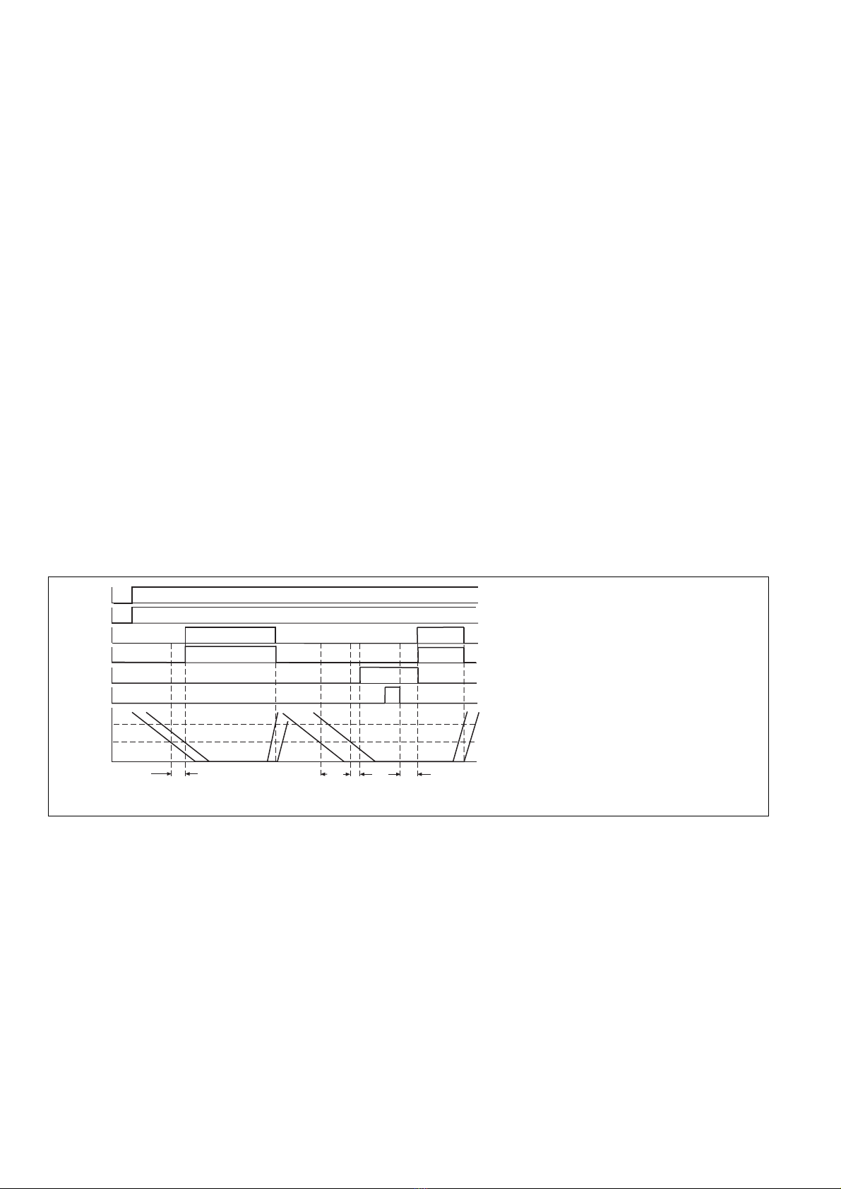
Einstellung und Ablauf
• Bei Motorstillstand Potentiometer nach
rechts drehen, dann Potentiometer nach
links drehen, bis die LEDs "Channel 1"und
"Channel 2" leuchten.
Die LED "Output" leuchtet noch nicht.
Die Sicherheitskontakte 13-14 und 23-24
sind geöffnet, der Hilfskontakt 41-42 ist
geschlossen, der Halbleiterausgang
Y31-Y32 ist hochohmig.
• Rückführkreis schließen, Motor anlaufen
lassen und wieder abschalten. Sobald
der Motor steht, leuchten die LEDs
"Channel 1", "Channel 2" und "Output"
und die Ausgangsrelais schalten. Die
Sicherheitskontakte 13-14 und 23-24 sind
geschlossen, der Hilfskontakt 41-42 ist
geöffnet, der Halbleiterausgang Y31-Y32
ist leitend.
Wieder aktivieren
• Der Rückführkreis muß geschlossen sein.
• Die Spannungen an den Meßkreisen
müssen gleichzeitig den Ansprechwert
(Stillstandsschwelle) unterschreiten.
• Leuchten die LEDs "Channel 1" und
"Channel 2" während des Gleichzeitig-
zeitraumes nicht gleichzeitig, dann ist
die Störmeldung an Klemme Y35 aktiv
und die LED "FAULT" leuchtet.
Das Gerät kann
- durch kurzes Unterbrechen der
Versorgungsspannung
- oder durch Anlegen und wieder
wegnehmen von 24 V DC an den
RESET-Eingang aktiviert werden.
Überprüfung - Fehlerursachen
Mit dem Selbsttest nach Einschalten der
Versorgungsspannung kann überprüft
werden, ob das Gerät ordnungsgemäß
auslöst bzw. sich wieder aktivieren läßt.
Das Gerät kann aus Sicherheitsgründen bei
folgenden Fehlern nicht gestartet werden:
• Fehlfunktion der Kontakte:
Bei verschweißten Kontakten ist nach
Öffnen des Eingangskreises keine neue
Aktivierung möglich
• Leitungsunterbrechung in Kanal 1 oder
Kanal 2
• Rückführkreis offen
Connection
• Connect the operating voltage between
A1i(+) and A2 (-).
• Measuring circuit
- single-phase motor: connect the Live to
L1 and the neutral conductor to L3. L1-
L2 must be linked.
- three-phase motor: connect the three
windings to L1, L2 and L3
• Feedback Control Loop
Connect the n/o contact of the relay to be
monitored to the feedback control loop
Y1-Y2 or - if not needed - bridge Y1-Y2.
• Semiconductor output:
Connect the terminal Y31 to the 24 V
Potential of the PLC, terminal Y30 to 0 V
and terminal Y32 to a PLC input.
• Semiconductor output for fault signalling:
Connect terminal Y31 to the PLC 24 V
supply, terminal Y30 to 0 V and terminal
Y35 to a PLC input.
• Semiconductor input for reset:
Connect the RESET terminal to a PLC
output.
To set and operate
• When the motor is at standstill turn
potentiometer to the right and then to the
left until the LEDs "Channel 1" and
"Channel 2" are illuminated. The LED
"Output" is not illuminated. The safety
contacts 13-14 and 23-24 are open, the
auxiliary contact 41-42 is closed and the
semiconductor output Y31-Y32 is non-
conducting.
• Close feedback control loop, run motor
and then switch off. When the motor
reaches the standstill threshold, the LEDs
"Channel 1", "channel 2" and "Output" are
illuminated and the output relays switch.
The safety contacts 13-14 and 23-24 are
closed, the auxiliary contact 41-42 is open
and the semiconductor output Y31-Y32
conducts.
Reactivation
• The feedback control loop must be closed.
• The voltages on the measuring circuits
must fall below the response value.
(standstill thresholds) simultaneously.
• If the "Channel 1" and "Channel 2" LEDs
do not light up simultaneously during the
simultaneity period then the
fault signal at terminal Y35 is active and
the LED "FAULT" lights up.
The device can be activated
- by briefly interrupting the supply voltage
- or by connecting and then removing 24
V DC to the RESET input.
Testing - Fault causes
After applying operating voltage, a self-test
is carried out to check that the unit functions
correctly.
For safety reasons, the unit cannot be
activated if the following faults are present:
• Faulty contact functions:
In the case of welded contacts, no further
activation is possible following an opening
of the input circuit.
• Cable break in channel 1 and channel 2
• Feedback control loop open
Branchement
• Raccorder la tension d'alimentation aux
bornes A1 (+) et A2 (-)
• Circuit mesure :
- Commande en 1 canal (moteur mono-
phasé): ramener la phase du moteur
sur L1, le neutre sur L3 et ponter les
bornes L1-L2.
- Commande en 2 canaux (moteur
triphasé) : ramener les trois phases du
moteur sur L1, L2 et L3
• Boucle de retour :
Câbler les contacts à ouverture des
contacteurs à surveiller dans la boucle de
retour Y1-Y2 ou - quand ce n'est pas
nécessaire - relier les bornes Y1-Y2.
• Sortie statique:
Ramener le 24 V à la borne Y31, le 0 V à
Y30 et relier la borne Y32 à une entrée
API.
• Sortie statique pour signal de défaut :
Raccorder la borne Y31 au potentiel 24 V
de l'API, la borne Y30 au potentiel 0 V et
la borne Y35 à l'entrée de l'API.
• Entrée statique pour Reset :
Raccorder la borne RESET à une sortie
de l'API.
Mise en oeuvre
• Le moteur étant à l'arrêt, tourner le
potentiomètre vers la droite, puis vers
la gauche jusqu'à ce que les LEDs
«Channel 1» et «Channel 2» s'allument.
La LED «Output» est encore èteinte. Les
contacts de sécurité 13-14 et 23-24 sont
ouverts, le contact d'info 41-42 est fermé,
la sortie statique Y31-Y32 est bloquée.
• Fermer la boucle de retour, mettre en
route le moteur puis le stopper. Dès que le
moteur est arrêté, les LEDs «Channel 1»,
«Channel 2» et «Output» s'allument et les
contacts de sécurité 13-14 et 23-24 se
ferment. Le contact d'info 41-42 est ouvert
et la sortie statique Y31-Y32 est passante.
Réarmement
• La boucle de retour est fermée.
• Les tensions mesurées sur les canaux
d'entrée doivent passer en dessous des
valeurs affichées dans l'intervalle de
temps autorisé (désynchronisme).
• Si les LEDs «Channel 1» et «Channel 2»
ne s'allument pas simultanément pendant
la période de synchronisme, le signal de
défaut à la borne Y35 est actif et la LED
«FAULT» s'allume.
L'appareil peut être activé
- en interrompant quelques instants la
tension d'alimentation
- ou en appliquant quelques instants une
tension de 24 V DC à l'entrée RESET.
Vérification - Sources d'erreur
L'autotest interne à la mise sous tension
permet de vérifier le bon déclenchement de
l'appareil et sa remise en marche.
Pour garantir la fonction de sécurité, le relais
n'est pas réarmé en si les défauts suivants se
produisent ::
• Défaut de fonctionnement des contacts de
sortie : cas de soudage d'un contact lors
de l'ouverture du circuit d'entrée, un
nouveau réarmement est impossible.
• Rupture de liaison sur les canaux 1 et 2.
• Boucle de retour ouverte.

S0: Aus-Schalter
S1: Ein-Schalter
S2/S4: Schutztür-Schalter
S3: Entriegelung
S5: Reset-Taster
H: Störmeldeleuchte
betätigtes Element
Tür offen
Tür geschlossen
Fig. 2: Anwendungsschaltung/Application switching/Connexion d'application
S0: Off switch
S1: On switch
S2/S4: Safety gate switch
S3: Release
S5: Reset button
H: Fault signal indicator
Switch operated
Door open
Door closed
S0: Commutateur d'arrêt
S1: Commutateur de marche
S2/S4: Interrupteur de position
S3: Déverrouillage
S5: Bouton de Reset
H: Témoin lumineux
d'anomalie
Elément actionné
Porte ouverte
Porte fermée
Anwendung
Gerät nur wie in folgendem Beispiel
beschrieben anschließen! Nicht bezeich-
nete Klemmen dürfen nicht angeschlos-
sen werden.
In dem Beispiel in Fig. 2 wird die Schutztüre
mit dem NOT-AUS-Schaltgerät und Schutz-
türwächter PNOZ X3 überwacht und durch
eine elektrischen Verriegelung gegen
unzulässiges Öffnen gesichert.
Beim Start der Maschine mit S1 schaltet K2
den Motor ein. Dabei wird geprüft, ob der
Stillstandswächter PSWZ X1P korrekt
anspricht. Nach Abschalten der Maschine
mit dem Taster S0 kann die Türe mit S3 ent-
riegelt werden, nachdem das PSWZ X1P
den Motorstillstand sicher erkannt hat.
Application
Only connect the unit as shown in the
example below! Do not connect
unlabelled terminals!
In the example Fig. 2 the safey gates are
monitored by the safety gate monitor PNOZ
X3 and with a safety interlock switch with a
solenoid release shot bolt, safe guards
against any unpermitted opening of the gates
.
By pressing S1, K2 closes and the motor
starts. When the PSWZ X1P output contacts
de-energise by detecting motor voltage, then
the supply to K2 coil is maintained. By
pressing the Stop button S0, the gates can
be un-locked by pressing S3, only after the
PSWZ X1P has detected standstill.
Utilisation
L'exemple de branchement ci-dessous
doit être respecté!
Les bornes non représentées ne doivent
pas être raccordées.
Dans l'exemple de la fig. 2, les protecteurs
mobiles sont contrôlés par un relais d'arrêt
d'urgence et par le détecteur de protecteur
mobile PNOZ X3. Les protecteurs mobiles
sont également protégés contre une
ouverture non autorisée grâce à un
verrouillage électrique. Au démarrage de la
machine à l'aide de S1, K2 met le moteur
sous tension. On vérifie que le détecteur
d'arrêt PSWZ X1P est correctement activé.
Après l'arrêt de la machine avec la touche
S0, le protecteur ne peut être déverrouillé
avec S3 qu'après détection de l'arrêt du
moteur par le PSWZ X1P.
S2
S4
L1
L2
L3
F1
S3
K3
S1 K2
S0 K1
K1 K2 K3 K4
F2
K2
K4
A1 13 23 L1 L3
14 24
Y31 Y32
A2Y1
41 L2
42
Y35
Y2
RESET
Y30
SPS
0 V 24 V
S5
PSWZ X1P
H
PNOZ X3
S13S12S11 S14S32S31
332313 41B1A1
B24234 A22414
S33S22S21 S34Y32Y31
IN

Technische Daten/Technical Data/Caractéristiques techniques
Elektrische Anforderungen/Electrical Data/Caractéristiques électriques
Versorgungsspannung UB /Operating Voltage UB /Tension d'alimentation UB24 ... 240 V AC/DC
Spannungstoleranz UB /Voltage Tolerance UB /Plage de la tension d'alimentation UB85-110 %
Frequenzbereich/Frequency Range/Fréquence AC: 50 ... 60 Hz
Leistungsaufnahme bei UB /Power Consumption at UB /Consommation pour UB
DC: ca./appx./env. 3 W
AC:
ca./appx./env.
5 VA
Kontakte/Contacts/Contacts
Ausgangskontakte/Output Contacts/Contacts de sortie
Sicherheitskontakte (S) nach/
safety contacts
(N/O) to
/contacts de sécurité
(F) d'après
EN 954-1, 07/96, Kategorie/category/catégorie 3
2
Hilfskontakte (Ö)/
auxiliary contacts (N/C)/contacts d'info (O) 1
Kontaktwerkstoff/Contact Material/Matériau des contacts AgCuNi
Gebrauchskategorie nach/Utilization category to/Catégorie d’utilisation d'après
EN 60947-4-1, 01/00 AC1: 240 V/0,005 ... 6 A/1500 VA
DC1: 24 V/0,005 ... 6 A/150 W
EN 60947-5-1, 08/00(DC13: 6 Schaltspiele/Min, 6 cycles/min, 6 manoeuvres/min) AC15: 230 V/3 A; DC13: 24 V/3A
Mechanische Lebensdauer/Mechanical Life/Durée de vie mécanique 1 x 10⁷ Schaltspiele/cycles/manoeuvres
Elektrische Lebensdauer/Electrical Life/Durée de vie électrique (1A/230V AC, cos.ϕ.=.1) 1 x 10⁵Schaltspiele/cycles/manoeuvres
Halbleiterausgänge/Semiconductor outputs/Sortie statique 24 V DC, 50 mA, PNP/kurzschlußfest/short-
circuit proof, /résist. aux courts-circuits
externe Spannungsversorgung/External supply voltage/Tension d'alimentation externe 24 V DC +/- 20 %
Halbleitereingang/Semiconductor input/entrée statique
"1"-Pegel (high)/"1"-Signal (high)/"1"-Niveau (haut) +15 ... 30 V DC
"0"-Pegel (low)/"0"-Signal/(low)/"0"-Niveau (bas) -3 ... +5 V DC
Eingangsstrom/Input current/Intensité d'entrée 20 mA
Resetzeit/Reset time/Temps de reset 10 ... 20 ms
Eigenschaften/Features/Particularités
Schaltschwelle je Kanal/Switching threshold per channel/Seuil de commutation par canal:
Ansprechwert Uan/Response time Uan/Valeur d'enclenchement Uan
Einstellbereich/Setting range/Plage de réglage PSWZ X1P 0,5V 20 ... 500 mV
Einstellbereich/Setting range/Plage de réglage PSWZ X1P 3V 0,12 ... 3 V
Rücksetzwert Uab/Release time Uab/Valeur de retombée Uab 2 Uan
Ansprechverzögerung/Delay-on Energisation/Temporisation à l’appel 0,4 ... 1,3 s
Rückfallverzögerung/Delay-on De-Energisation/Temps de retombée < 170 ms
Anzugsverzögerung nach Ausfall und Wiederkehr der Versorgungsspannung 1,4 ... 2,2 s
Delay-on Energisation after failure and applying operating voltage again
Temps de réaction après coupure et remise sous tension
Gleichzeitigkeitsbedingung (max. Zeitdifferenz tgzwischen Kanal 1 und Kanal 2) 3,0 ... 8,0 s
Simultaneity Requirements (max. Time delay tg between channel 1 and channel 2)
Synchronisation temporelle (différence de temps tg max. entre les canaux 1 et 2)
Meßkreis/Measuring circuit/Circuit mesure:
Eingangsspannung /Input Voltage/Tension d'entrée L1-L3, L1-L2, L2-L3 0 ... 690 V AC/DC
Eingangsspannung gemäß UL/Input voltage in accordance with UL/Tension d’entrée
conformément à UL 0 ... 600 V AC
Frequenzbereich/Frequency range/Fréquence 0 ... 3 kHz
Eingangsimpedanz/Input Impedance/Impédance d'entrée ca./appx./env. 1,3 M Ω
Grenzbelastbarkeit/Loading capacity limit/Caractéristiques de commutation
Max. zulässiger Einschaltstrom (Ausgangskonakte)/Max. permitted inrush current (on the outputs) 10 A, max. 20 ms
Pouvoir de coupure admissible max. (Contacts de sortie)
Elektromagnetische Verträglichkeit (EMV)/Electromagnetic Compatibility to EN 50081-1, 01/92
Compatibilité électromagnétique (CEM) d'après EN 61000-6-2, 03/00
Luft- und Kriechstrecken nach/Airgap Creepage/Cheminement et claquage DIN VDE 0110-1, 04/97
Kontaktabsicherung extern nach/External Contact Fuse Protection/Protection des contacts
EN 60 947-5-1
Schmelzsicherung/Blow-out fuse/Fusibles max. 6 A flink/quick/rapide oder/or/ou
max. 4 A träge/slow acting/normaux
Sicherungsautomat/Safety cut-out/Dijoncteur 24 V AC/DC: 4 A
Charakteristik / Characteristic /
Caractéristiques B/C
Geräteabsicherung min./max. 2 A/abhängig vomLeitungsquerschnitt
Unit Fuse Protection min./max. 2 A/dependentoncable crosssection
Protection du relais min./max. 2 A/dépend du diamêtre du câblage
Umgebungsbedingungen/Environment Conditions/Environnement
Umgebungstemperatur/Ambient Temperature/Température d'utilisation -10 ... +55 °C
Lagertemperatur/Storage Temperature/Température de stockage -40 ... +85 °C
Klimabeanspruchung/Climate Suitability/Conditions climatiques DIN IEC 60068-2-3, 12/86
Schwingungen nach/Vibration to/Vibrations d'après EN 60068-2-6, 01/00 Frequenz/Frequency/Fréquences: 10-55 Hz
Amplitude/Amplitude/Amplitude: 0,35 mm

Allgemeine Angaben zum Gerät/General Information - Unit/Caractéristiques du boîtier
Max.Querschnitt des Außenleiters (Schraubklemmen)/Max. cable cross section (screw
terminals)/Capacité de raccordement (borniers à vis)
Einzelleiter/Single- core/Conducteur unique
flexibel ohne Aderendhülse/flexible without crimp connectors/souple sans embout 0,2 ... 2,5 mm²
flexibel mit Aderendhülse/flexible with crimp connectors/souple avec embout 0,25 ... 2,5 mm²
Mehrleiter (2 Leiter gleichen Querschnitts)/Multi-core (2 cables with the same cross
section)/Conducteur multiple (2 câbles de même diamètre)
flexibel mit Aderendhülse ohne Kunststoffhülse/flexible with crimp connectors without
insulating sleeve /souple avec embout sans chapeau plastique 0,25 ... 1 mm²
flexibel mit TWIN-Aderendhülse mit Kunststoffhülse/flexible with TWIN crimp
connectors 0,5 ... 1,5 mm²
with insulating sleeve/souple avec embout TWIN avec chapeau plastique
Max.Querschnitt des Außenleiters (Käfigzugfederklemmen) /Max. cable cross section (cage
clamp terminals)/Capacité de raccordement (borniers à ressort)
flexibel ohne Aderendhülse/flexible without crimp connectors/souple sans embout 0,2 ... 1,5 mm²
Gehäuse mit Käfigzugfederklemmen/Housing with cage clamp terminals/
Boîtier avec borniers à ressort/
Abisolierlänge/Stripping length/Longueur de dénudage/ 8 mm
Klemmstellen pro Anschluss/Terminal blocks per connection/bornes par raccordement 2
Anzugsdrehmoment für Anschlußschrauben (
Schraubklemmen
)/
Torque setting for connection screws
(screw terminals)
/
Couple de serrage (borniers à vis) 0,6 Nm
Schutzarten/Protection/Indice de protection:
Einbauraum (z. B. Schaltschrank)/Mounting (e.g. Panel)/Lieu d'implantation (ex. armoire) IP 54
Gehäuse/Housing/Boîtier IP 40
Klemmenbereich/Terminals/Bornes IP 20
Gehäusematerial/Housing material/Matériau boîtier Kunststoff/Plastic/Plastique
Thermoplast Noryl SE 100
Abmessungen (Schraubklemmen) H x B x T/Dimensions H x W x D (screw terminals)/
Dimensions (borniers à vis) H x P x L 94 (3.70") x 45 (1.77") x 121 (4.76") mm
Abmessungen (Käfigzugfederklemmen) H x B x T/Dimensions (cage clamp terminals)
H x W x D/ Dimensions (borniers à ressort) H x L x P 101 (3.98") x 45 (1.77") x 121 (4.76") mm
Gewicht/Weight/Poids 320 g
Abmessungen in mm ('')/Dimensions in mm ('')/Dimensions in mm ('')
Gehäuse mit steckbaren Schraubklemmen/
Housing with plug-in screw terminals/
Boîtier avec borniers débrochables à vis
Gehäuse mit steckbaren Käfigzugfederklemmen/
Housing with plug-in cage clamp terminals/
Boîtier avec borniers débrochables à ressort
75 (2.95")
94 (3.70")
121 (4.76")
45
(1.77")
87 (3.42")
45
(1.77")
75 (2.95")
101 (3.98")
121 (4.76")
87 (3.42")

A
AUS
Pilz Australia Industrial Automation LP., ✆03 95446300, Fax: 03
B L
BR
Pilz do Brasil Sistemas Eletrônicos
Industriais Ltda., ✆11 4337-1241, Fax: 11 4337-1242, E-Mail: pilz@pilzbr.com.br
CH
Pilz lndustrieelektronik GmbH, ✆062 88979-30, Fax: 062 88979-40,
DK
E
Pilz lndustrieelektronik S.L., ✆938497433, Fax:
F
FIN
Pilz Skandinavien K/S,
✆09 27093700, Fax: 09 27093709, E-Mail: pilz.f[email protected]
GB
I
IRL
Pilz Ireland Industrial Automation, ✆021 4346535, Fax: 021 4804994, E-Mail:
J
MEX
Pilz de Mexico, S. de R.L. de C.V., ✆55 5572 1300,
NL
NZ
Pilz New Zealand, ✆09-
P
PRC
Pilz
China Representative Office, ✆021 62493031, Fax: 021 62493036,
ROK
Pilz Korea Office, ✆031 8159541, Fax: 031 8159542,
E-Mail: info@pilzkorea.co.kr
SE
TR
Pilz Elektronik Güvenlik Ürünleri ve
USA
Pilz Automation Safety L.P., ✆734 354-0272, Fax: 734 354-3355,
E-Mail: [email protected]
www
www.pilz.com
D
Pilz GmbH & Co. KG, Sichere Automation, Felix-Wankel-Straße 2, 73760 Ostfildern, Deutschland, ✆+49 711 3409-0, Fax: +49 711 3409-133,
E-Mail: [email protected]
21 005-02-04/04 Printed in Germany

Nr. 21 005-02
PSWZ X1P
Instrucciones de uso
Istruzioni per l’uso
Gebruiksaanwijzing
Prescripciones de seguridad
•
El dispositivo tiene que ser instalado y
puesto en funcionamiento exclusivamente
por personas que estén familiarizadas tanto
con estas instrucciones de uso como con las
prescripciones vigentes relativas a la
seguridad en el trabajo y a la prevención de
accidentes. Hay que observar tanto las
prescripciones VDE como las prescripciones
locales, especialmente en lo que se refiere a
las medidas de protección.
• Durante el transporte, el almacenaje y el
funcionamiento hay que atenerse a las
condiciones conforme a EN 60068-2-6, 01/00
(ver datos técnicos).
• La garantía se pierde en caso de que se
abra la carcasa o se lleven a cabo
remodelaciones por cuenta propia.
• Montar el dispositivo dentro de un armario de
distribución; en caso contrario es posible que
el polvo y la suciedad puedan afectar el
funcionamiento.
• Hay que cuidar de que haya un conexionado
de seguridad suficiente en todos los
contactos de salida con cargas capacitivas e
inductivas.
Campo de aplicación adecuado
El supervisor de parada PSWZ X1P sirve como
dispositivo de seguridad para la supervisión de
parada. El PSWZ X1P ha sido diseñado para
ser empleado en
• Supervisiones de parada en instalaciones
con partes de maquinaria o herramientas
peligrosas (EN 1088 párr. 7.4)
• Circuitos de seguridad según VDE 0113-1,
11/98 e IEC 204-1, 11/98
Descripción del dispositivo
El supervisor de parada se encuentra montado
dentro de una carcasa P-99. La tensión de
alimentación es de 24 ... 240 V AC /DC.
Características:
• Salidas de relé:
2 contactos de seguridad (NA), de guiado
mecánico
1 contacto auxiliar (NC), de guiado mecánico
• 2 salidas por semiconductor separadas
galvánicamente, para estado de
conmutación, mensaje de averías
• Entrada por semiconductor para función de
reset
• LED como indicación de la tensión de
alimentación, indicación de parada para
canal 1 y 2, indicación del estado de
conmutación, Visualización de errores
• Autocomprobación automática al conectar
• Conexión redundante de salida
• Modo monocanal o bicanal
• Entradas de medición para motores trifásicos
o monofásicos
•
Tensión de medición de ambos canales
ajustable al unísono
• Circuito de realimentación para la
supervisión de contactores externos
Norme di sicurezza
•
Il dispositivo può venire installato e messo in
funzione solo da persone che hanno acqisito
familiarità con le presenti istruzioni per l’uso
e le disposizioni vigenti in materia di
sicurezza di lavoro e antinfortunistica.
Osservare le disposizioni della VDE
(Associazione elettrotecnica tedesca) nonché
le norme locali, soprattutto per quanto
riguarda le misure preventive di protezione.
• Per il trasporto, l’immagazzinamento e
l’esercizio attenersi alle condizioni prescritte
dalla norma EN 60068-2-6, 01/00 (v. Dati
tecnici).
• In caso di apertura della custodia o di
modifiche non autorizzate sul dispositivo,
decade qualsiasi diritto di garanzia.
• Montare il dispositivo in un armadio elettrico;
polvere e umidità possono pregiudicare le
funzionalità dell'apparecchio.
• Occorre dotare tutti i contatti di uscita dei
carichi capacitivi e induttivi con un 'adeguata
protezione.
Uso previsto
Il dispositivo di controllo di motore fermo
PSWZ X1P è un apparecchio destinato a
garantire un controllo sicuro del fermo
macchina PSWZ X1P è concepito per essere
utilizzato in
• Controlli di motore fermo su impianti dotati
di componenti o utensili pericolosi (EN 1088
par. 7.4)
• Circuiti di sicurezza conformi alle norme
VDE 0113-1, 11/98 e IEC 204-1, 11/98
Descrizione del dispositivo
Il dispositivo di controllo di motore fermo è
inserito in una custodia P-99. La tensione di
alimentazione è di 24 ... 240 V AC /DC.
Caratteristiche:
• Uscite relè:
2 contatti di sicurezza (NA), forzati
1 contatto ausiliario (NC), forzato
• 2 uscite a semiconduttore, con separazione
galvanica, per lo stato di commutazione e la
segnalazione delle anomalie
• Ingresso a semiconduttore per la funzione
reset
• LED per indicazione della tensione di
alimentazione, indicazione di fermo per
canali 1 e 2, indicazione stato di
commutazione, indicatore de errore
• Autotest automatico al momento
dell’accensione
• Circuito d’uscita ridondante
• Funzionamento mono o bicanale
• Ingressi di misura per motori monofase o
trifase
• La tensione di misura è impostabile insieme
per entrambi i canali
• Circuito di retroazione per il controllo di relè
esterni
Veiligheidsvoorschriften
•
Het apparaat mag uitsluitend worden
geïnstalleerd en in bedrijf genomen door
personen die vertrouwd zijn met deze
gebruiksaanwijzing en met de geldende
voorschriften op het gebied van arbeids-
veiligheid en ongevallenpreventie. Neemt u
de van toepassing zijnde Europese richtlijnen
en de plaatselijke voorschriften in acht, in het
bijzonder m.b.t. de veiligheidsmaatregelen.
• Neemt u bij transport, opslag en in bedrijf de
richtlijnen volgens EN 60068-2-6, 01/00 in
acht (zie technische gegevens).
• Het openen van de behuizing of het
eigenmachtig veranderen van de schakeling
heeft verlies van de garantie tot gevolg.
• Monteert u het apparaat in een schakelkast.
Stof en vochtigheid kunnen anders de
werking nadelig beïnvloeden.
• Zorgt u bij capacitieve of inductieve belasting
van de uitgangscontacten voor adequate
contactbeschermingsmaatregelen.
Toegelaten applicaties
Het stilstandsbewakingsrelais PSWZ X1P dient
als veilige inrichting om de stilstand te
bewaken. De PSWZ X1P is bestemd voor
gebruik in
• stilstandsbewakingen bij installaties met
gevaarlijke machinedelen of gereedschappen
(EN 1088 par. 7.4)
• veiligheidscircuits volgens
VDE 0113-1, 11/98 en IEC 204-1, 11/98
Apparaatbeschrijving
Het stilstandsbewakingsrelais is in een P-99-
behuizing ondergebracht. De voedingsspanning
bedraagt 24 ... 240 V AC /DC.
Kenmerken:
• Relaisuitgangen:
2 veiligheidscontacten (M), mechanisch
gedwongen
1 hulpcontact (V), mechanisch gedwongen
• 2 halfgeleideruitgangen, galvanisch
gescheiden, voor schakeltoestand,
storingsmelding
• Halfgeleideruitgang voor resetfunctie
• LED’s voor weergave van voedingsspanning,
weergave van stilstand van kanaal 1 en 2,
weergave van de schakeltoestand,
foutmelding
• Automatische zelftest bij het inschakelen
• Redundante uitgangsschakeling
• Een- of tweekanalig bedrijf
• Meetingangen voor drie- of eenfasemotoren
• Meetspanning van beide kanalen
gezamenlijk instelbaar
• Terugkoppelcircuit voor de bewaking van
externe magneetschakelaars

Y1-Y2
13-14
23-24
UL1/UL2
Uan
Uab
t<tg
UB
Y35
t
>tg
RESET
ca.50 ms
1,5 s
Fig.1: Diagrama funcional/Diagramma funzionale/Functiediagram
tg= Condición de simultaneidad
Requisiti di simultaneità
Gelijktijdigheidsfactor
• El supervisor de parada impide la utilización
de la instalación en los casos siguientes:
- Corte de la tensión
- Fallo de un elemento constructivo
- Interrupción de los circuitos de medición
- Defecto de bobina/rotura de línea
• Comprobación, con cada ciclo de conexión/
desconexión, de si los relés de salida del
dispositivo de seguridad abren y cierran
correctamente.
Descripción del funcionamiento
El dispositivo registra, con dos canales de
medición separados, la tensión inducida en el
bobinado del motor que se produce durante la
marcha por inercia del eje motriz. Cuando la
tensión queda por debajo del valor de
respuesta ajustado (umbral de parada), el
supervisor de parada permite la utilización la
instalación que se ha de supervisar.
Si se utiliza un convertidor de frecuencia, el
PSWZ X1P no identifica las paradas si está
conectado el bloqueo de regulación.
Despues de conectar la tensión de
alimentación UBel dispositivo ejecuta una
autocomprobación. Una vez transcurrida la
autocomprobación se iluminan los LEDs
"Power", "Channel 1", "Channel 2" y "Output",
siempre que la tensión en ambos canales sea
menor al valor de respuesta Uan, los circuitos
de medición no estén interrumpidos y el
circuito de realimentación (Y1-Y2) esté
cerrado. Ambos relés de salida K1 y K2 están
en posición de trabajo, la salida por
semiconductor Y31-Y32 es conductora. Los
contactos de seguridad 13-14 y 23-24 están
cerrados y, el contacto auxiliar 41-42 está
abierto.
• Il dispositivo di controllo di stato impedisce
nei seguenti casi l’attivazione dell’impianto:
- Caduta di tensione
- Guasto di un componente
- Interruzione dei circuiti di misura
- Difetto della bobina / rottura dei cavi
• Per ciascun ciclo di accensione/spegnimento
viene eseguita la verifica della corretta
apertura dei relè di uscita del dispositivo di
sicurezza.
Descrizione del funzionamento
Mediante due canali di misura separati,
l’apparecchio rileva la tensione indotta
nell’avvolgimento del motore prodotta durante
la fase di arresto dell’albero motore. Se la
tensione risulta inferiore al valore soglia
(soglia di arresto), il dispositivo di controllo di
fermo consente l’attivazione dell’impianto
sottoposto al controllo.
Se utilizzato con un convertitore di frequenza,
PSWZ X1P può riconoscere il fermo motore
solo in caso di disattivazione del pilotaggio
della uscita.
Dopo l’attivazione della tensione di
alimentazione UB, l’apparecchio esegue un
autotest.
Se la tensione su entrambi i canali è inferiore
al valore soglia Uan, i circuiti di misura non
sono interrotti e il circuito di retroazione (Y1-
Y2) è chiuso, terminato l’autotest, i LED
"Power", "Channel 1", "Channel 2" e "Output"
si accendono. I due relè di uscita K1 e K2
sono in posizione di lavoro, l’uscita a
semiconduttore Y31-Y32 è conduttrice. I
contatti di sicurezza 13-14 e 23-24 sono chiusi
ed il contatto ausiliario
41-42 aperto.
• Het stilstandsbewakingsrelais verhindert in
de volgende gevallen dat de installatie
vrijgegeven wordt:
- uitvallen van de spanning
- uitvallen van een component
- onderbreking van de meetcircuits
- defect in een spoel/kabelbreuk
• Bij elke aan-uitcyclus wordt automatisch
getest of de uitgangsrelais van de
veiligheidsvoorziening correct openen en
sluiten
Functiebeschrijving
Het apparaat registreert met twee gescheiden
meetkanalen de in de motor geïnduceerde
spanning, die bij het uitlopen van de motor
ontstaat. Als de spanning de ingestelde
aanspreekwaarde (stilstandsdrempel)
onderschrijdt, geeft het stilstandsbewa-
kingsrelais de te bewaken installatie vrij.
Bij gebruik in combinatie met
frequentieregelaars, kan de PSWZ X1P pas
stilstand detecteren nadat de blokkering van
de regelaar is uitgezet.
Na het inschakelen van de voedingsspanning
UBvoert het apparaat een zelftest uit. Nadat
de zelftest afgelopen is, lichten de LED’s
"Power", "Channel 1", "Channel 2" en "Output"
op, op voorwaarde dat de spanning op beide
kanalen kleiner is dan de aanspreekwaarde
Uan, de meetcircuits niet onderbroken zijn en
het terugkoppelcircuit (Y1-Y2) gesloten is. De
beide uitgangsrelais K1 en K2 worden
bekrachtigd, de halfgeleideruitgang Y31-Y32
is geleidend. De veilig-heidscontacten 13-14
en 23-24 zijn gesloten en het hulpcontact 41-
42 is geopend.
Si después de ponerse en marcha el motor, la
tensión sobrepasa el valor de reposición U
ab
en
alguno de los dos circuitos de medición, los
relés de salida vuelven a la posición de reposo
y los contactos de seguridad 13-23 y 23-24 se
abren y el contacto de seguridad 41-42 se
cierra, la salida por semiconductor Y31-Y32
está bloqueada. Los LEDs "Channel 1",
"Channel 2" y "Output" se apagan.
Para la reactivación, la tensión en ambos
canales debe quedar por debajo del valor de
respuesta U
an
dentro del tiempo t
g
(supervisión
de simultaneidad). Para ello, el circuito de
realimentación Y1-Y2 debe estar cerrado.
El valor de respuesta Uan puede ajustarse a
ambos canales conjuntamente, para
adaptación al motor que se ha de
supervisar.
El valor de reposición U
ab
(histéresis) se corresponde con el doble del
valor de respuesta.
Se, dopo l’accensione del motore in uno dei
due circuiti di misura, la tensione supera il
valore di reset Uab, i relè di uscita si
diseccitano ed i contatti di sicurezza 13-23 e
23-24 si aprono, mentre il contatto ausiliario
41-42 si chiude e l’uscita a semiconduttore
Y31-Y32 è bloccata. I LED "Channel 1",
"Channel 2" e "Output" si spengono.
Per riattivare il sistema, la tensione su
entrambi i canali deve risultare inferiore al
valore soglia Uan entro l’intervallo tg(controllo
di simultaneità). Il circuito di retroazione Y1-Y2
deve essere chiuso.
Un unico valore soglia Uan può essere
impostato, per entrambi i canali,
relativamente al motore da controllare.
Il valore di reset Uab (isteresi) corrisponde al
doppio del valore soglia.
Als de spanning na het aanlopen van de motor
in een van de beide meetcircuits de
resetwaarde Uab, overschrijdt, vallen de
uitgangsrelais af en de veiligheidscontacten
13-23 en 23-24 gaan open en het hulpcontact
41-42 sluit, de halfgeleideruitgang Y31-Y32 is
geblokkeerd. De LED’s "Channel 1", "Channel
2" en "Output" doven.
Om opnieuw te activeren, moet de spanning
op beide kanalen de aanspreekwaarde Uan
binnen de tijd tg(gelijktijdigheidsbewaking)
onderschrijden. Het terugkoppelcircuit Y1-Y2
moet daartoe gesloten zijn.
Voor de aanpassing aan de te bewaken
motor kan de aanspreekwaarde Uan voor
beide kanalen gezamenlijk ingesteld worden.
De resetwaarde Uab (hysterese) komt overeen
met de dubbele aanspreekwaarde.

Si se sobrepasa la condición de
simultaneidad,se enciende el LED „FAULT“
y la salida por semiconductor Y31-Y35
conduce corriente.
El supervisor de parada no
permite la utilización de la instalación que se ha
de supervisar. Aplicando y quitando
nuevamente 24 V CC en la entrada RESET es
posible activar de nuevo el dispositivo.
Autocomprobación
El dispositivo simula el sobrepaso del valor de
reposición y la presencia de una rotura de línea
en el circuito de medición. Adicionalmente se
verifica el funcionamiento correcto del relé de
salida y del circuito de realimentación. La
comprobación dura aprox. 1,5 s.
Funciones de seguridad
Los relés K1 y K2 están enclavados uno
contra el otro (Fail Safe Block) de tal manera
que, en caso de una fusión de contactos o
rotura de hilo no es posible la reconexión.
El dispositivo supervisa la presencia de rotura
de línea en los circuitos de medición. Si se
presenta una rotura de línea entre dispositivo
y motor o en el propio motor, el PSWZ X1P se
desconecta inmediatamente.
Modos de funcionamiento
• Funcionamiento monocanal:
- un circuito de medición actúa sobre
ambos canales
-
sin redundancia (seguridad contra
interrupción) en los circuitos de medición
• Funcionamiento bicanal:
- dos circuitos de medición redundantes
(es decir idénticos) actúan sobre el
canal 1 y el canal 2
- supervisión de las tensiones en el circuito
de medición (seguridad contra
interrupción por cortocircuito)
Montaje
El dispositivo tiene que ser montado dentro de
un armario de distribución con un grado de
protección de IP 54 como mínimo. El
dispositivo dispone, en su lado trasero, de un
elemento de encaje para la fijación a una guía
normalizada.
Al montar el dispositivo en una guía
normalizada vertical (35 mm) hay que
asegurarlo por medio de un elemento de
soporte, tal como un soporte o un ángulo final.
Puesta en marcha
Al poner en marcha hay que tener en cuenta:
•Conectar un fusible antes de los
contactos de salida (6 A de acción
rápida ó 4 A de acción lenta) con objeto
de evitar la fusión de los contactos.
• No conectar corrientes pequeñas a
contactos a través de los cuales se han
conducido anteriormente grandes
corrientes.
•
No utilizar el contacto auxiliar 41-42 para
circuitos de seguridad.
• Utilizar para las líneas material de alambre
de cobre con una resistencia a la
temperatura de 60/75 °C.
• El par de apriete de los tornillos en los
bornes de conexión debe ser de 0,6 Nm
como máximo.
•En trabajo con variador: Utilice un cable
apantallado para el cableado entre el PSWZ
X1P y el motor y conecte el apantallado al
motor.
• Respetar sin falta las indicaciones del
capítulo "Datos técnicos".
Se il requisito di simultaneità viene superato, il
LED „FAULT“ si illumina e l’uscita a
semicoduttore Y31-Y35 conduce. Il
dispositivo di controllo di fermo non consente
l’attivazione dell'impianto. Applicando e
togliendo di nuovo la tensione a 24V DC
dall'ingresso RESET, l’apparecchio può
essere nuovamente riattivato.
Autotest
L’apparecchio simula il superamento del
valore reset e la rottura di un conduttore nel
circuito di misura.
Inoltre, viene anche verificato
il corretto funzionamento del relè di uscita e del
circuito di retroazione. Il test dura
circa 1,5 s.
Funzioni di sicurezza
I relè K1 e K2 sono bloccati reciprocamente
(Fail Safe Block), in modo tale che, nel caso di
saldatura di contatti o rottura di cavi, non sia
possibile eseguire una riaccensione.
L’apparecchio controllo i circuiti di misura per
verificare l’integrità dei cavi. Nel caso di rottura
del cavo tra l’apparecchio ed il motore o nel
motore stesso, il modulo PSWZ X1P si
disattiva immediatamente.
Modalità operative
• Funzionamento a singolo canale:
- un circuito di misura agisce su entrambi i
canali
- nessuna ridondanza (fail-safe) nei circuiti
di misura
• Funzionamento a doppio canale:
- due circuiti di misura ridondanti (identici)
agiscono sui canali 1 e 2
- controllo delle tensioni nel circuito di
misura (fail-safe per prevenire un
cortocircuito)
Montaggio
Il dispositivo va montato in un armadio
elettrico con un grado di protezione pari ad
almeno IP 54. Un dispositivo a scatto sul retro
del dispositivo consento di fissarlo su una
guida DIN.
In fase di montaggio, fissare il dispositivo su
una guida verticale a norma (35 mm) a mezzo
di supporti quali p. es. staffe di fissaggio o
angoli terminali.
Messa in funzione
Alla messa in funzione occorre
considerare quanto segue:
•
Per evitare la saldatura dei contatti, colle-
gare un fusibile (6 A rapido o 4 A ritarda-
to) a monte ritardato dei contatti di uscita.
• Non commutare piccole correnti con contatti
attraverso i quali sono state commutate in
precedenza alte correnti.
•
Non utilizzare il contatto ausiliario 41-42 per
i circuiti di sicurezza.
• Per i cavi utilizzare materiale in filo di rame
con una resistenza termica intorno ai 60/75
°C .
• La coppia di serraggio delle viti sui morsetti
non deve superare 0,6 Nm.
•Durante il funzionamento del
convertitore: Per il cablaggio tra PSWZ
X1P e il motore utilizzare un cavo
schermato. Collegare lo schermo del cavo
al motore.
Als de gelijktijdigheidsfactor overschreden
wordt, brandt de LED „Fault“ en de
halfgeleideruitgang Y31-Y35 is geleidend.
Het stilstandsbewakingsrelais geeft de te
bewaken installatie niet vrij. Door het
inschakelen en weer wegnemen van 24 V DC
op de resetingang kan het apparaat weer
geactiveerd worden.
Zelftest
Het apparaat simuleert dat de resetwaarde
overschreden wordt en dat er een kabelbreuk
optreedt in het meetcircuit. Bovendien wordt
gecontroleerd of de uitgangsrelais en het
terugkoppelcircuit correct functioneren. De
test duurt ca. 1,5 s.
Veiligheidsfuncties
De relais K1 en K2 zijn zo ten opzichte van
elkaar vergrendeld (failsafe blok), dat in geval
van verkleefde contacten of een kabelbreuk
het niet mogelijk is om opnieuw in te
schakelen.
Het apparaat bewaakt de meetcircuits op
kabelbreuk. Als er een kabelbreuk optreedt
tusssen apparaat en motor of op de motor
zelf, dan schakelt de PSWZ X1P direct af.
Bedrijfsmodi
• Eenkanalig bedrijf:
- Eén meetcircuit werkt op beide kanalen
- Geen redundantie (uitvalveiligheid) in
de meetcircuits
• Tweekanalig bedrijf:
- Twee redundante (d.w.z. identieke)
meetcircuits werken op kanaal 1 en 2
- Bewaking van de spanning in het
meetcircuit (uitvalveiligheid tegen
kortsluiting)
Montage
Het relais moet ingebouwd worden in een
schakelkast die minimaal voldoet aan IP54.
Bevestiging op een DIN-rail is mogelijk via de
daarvoor bestemde relaisvoet.
Bij montage op een verticale draagrail
(35 mm) moet het apparaat worden vastgezet
met een eindsteun.
Ingebruikneming
Neemt u bij ingebruikneming het volgende
in acht:
•Uitgangscontacten afzekeren (6 A snel
of 4 A traag) om het verkleven van de
contacten te voorkomen.
• Geen geringe stroomsterkten via contacten
schakelen die tevoren grote stroomsterkten
verwerkt hebben.
•
Hulpcontact 41-42 niet voor veiligheids-
circuits gebruiken.
• Kabelmateriaal van koperdraad met een
temperatuurbestendigheid van 60/75 °C
gebruiken.
• Het aanhaalmoment van de schroeven op
de aansluitklemmen mag max. 0,6 Nm
bedragen.
•In converter bedrijf: Gebruik voor de
bedrading tussen de PSWZ X1P en de
motor een afgeschermde kabel. Verbindt de
afscherming van de kabel met de motor.
• Aanwijzingen in het hoofdstuk "Technische
gegevens" beslist opvolgen.

•
En funcionamiento con seguridad elevada
(por ej. supervisión de parada segura) se
debe ejecutar, por lo menos semanalmente,
la siguiente comprobación:
- Poner el motor en marcha. Todos los
LEDs se apagan, excepto "Power". Los
contactos 13-14 y 23-24 deben estar
abiertos, y 41-42 cerrados.
- Desconectar nuevamente el motor. Sólo
después de que se haya detenido el eje
motriz, se deben encender los LEDs
"Channel 1", "Channel 2" y "Output" o los
contactos 13-14 y 23-24 se deben cerrar,
y 41-42 abrir.
Conexión
• Conectar la tensión de alimentación en los
bornes A1 (+) y A2 (-).
• Circuito de medición
- Motor monofásico: conectar la fase del
motor en L1, el conductor neutro en L3.
Puentear los bornes L1-L2.
- Motor trifásico: conectar las tres fases del
motor en los bornes L1, L2 y L3.
• Circuito de realimentación
- Conectar los contactos normalmente
cerrados de los contactores que se han
de supervisar al circuito de
realimentación Y1-Y2, o bien, si no se
necesita, puentear Y1-Y2.
• Salida por semiconductor para estado de
conmutación:
Conectar el borne Y31 al potencial de 24 V
del PLC, el borne Y30 a 0 V y el borne Y32
a una entrada del PLC.
• Salida por semiconductor para mensaje de
averías:
Conectar el borne Y31 al potencial de 24 V
del PLC, el borne Y30 a 0 V y el borne Y35
a una entrada del PLC.
• Entrada por semiconductor para reset:
Conectar el borne RESET a una salida del
PLC.
Ajuste y desarrollo
•
Con el motor detenido girar ambos
potenciómetros hacia la derecha, después
girar el potenciómetro hacia la izquierda hasta
que se iluminen los LEDs "Channel 1" y
"Channel 2".
El LED "Output" no se ilumina todavía.
Los contactos de seguridad 13-14 y 23-24
están abiertos, el contacto auxiliar 41-42 está
cerrado, la salida por semiconductor
Y31-Y32 es de alta impedancia.
• Cerrar el circuito de realimentación, poner el
motor en marcha y desconectar nuevamente.
En cuanto se detiene el motor, se iluminan
los LEDs "Channel 1", "Channel 2" y "Output",
y conmutan los relés de salida. Los contactos
de seguridad 13-14 y 23-24 están cerrados,
el contacto auxiliar 41-42 está abierto, la
salida por semiconductor Y31-Y32 es
conductora.
Activar de nuevo
• El circuito de realimentación tiene que estar
cerrado.
•
Las tensiones en los circuitos de medición
deben quedar, simultaneamente, por debajo
del valor de respuesta (umbral de parada).
• Si no se iluminan simultaneamente los LEDs
"Channel 1" y "Channel 2" durante el
intervalo de simultaneidad, entonces está
activo el mensaje de averías en el borne Y35
y se enciende el LED "FAULT".
El dispositivo se puede
- activar mediante una breve interrupción
de la tensión de alimentación
- o aplicando y quitando nuevamente 24 V
CC en la entrada RESET.
• Bij gebruik met een verhoogd veiligheids-
niveau (b.v. veilige stilstandsbewaking)
moet minstens wekelijks de volgende test
uitgevoerd worden:
- Motor laten aanlopen. Alle LED’s behalve
"Power" moeten doven. De contacten 13-
14 en 23-24 moeten geopend en 41-42
gesloten zijn.
- Motor weer afschakelen. De LED’s
"Channel 1", "Channel 2" en "Output"
mogen pas oplichten dan wel de
contacten 13-14 en 23-24 gesloten en
41-42 geopend zijn, als de motor tot
stilstand gekomen is.
Aansluiting
• Voedingsspanning op klemmen A1 (+) en
A2 (-) aansluiten.
• Meetcircuit
- Eenfasemotor: de fase van de motor op
L1, de nulleider op L3 aansluiten.
Klemmen L1-L2 verbinden.
- Driefasemotor: de drie fasen van de
motor op de klemmen L1, L2 en L3
aansluiten.
• Terugkoppelcircuit
- Verbreekcontacten van de te bewaken
magneetschakelaars op terugkoppel-
circuit Y1-Y2 aansluiten of - indien niet
nodig - Y1-Y2 verbinden.
• Halfgeleideruitgang voor schakeltoestand:
Klem Y31 op de 24-V-potentiaal van de
PLC, klem Y30 op 0 V en klem Y32 op een
PLC-ingang aansluiten.
• Halfgeleideruitgang voor storingsmelding:
Klem Y31 op de 24-V-potentiaal van de
PLC, klem Y30 op 0 V en klem Y35 op een
PLC-ingang aansluiten.
• Halfgeleideruitgang voor reset:
De klem RESET op een PLC-uitgang
aansluiten.
Instelling en verloop
• Bij motorstilstand potentiometer naar rechts
draaien, dan de potentiometer naar links
draaien, tot de LED’s "Channel 1" en
"Channel 2" oplichten.
De LED "Output" licht nog niet op.
De veiligheidscontacten 13-14 en 23-24 zijn
geopend, het hulpcontact 41-42 is gesloten,
de halfgeleideruitgang
Y31-Y32 is hoogohmig.
• Terugkoppelcircuit sluiten, motor laten
aanlopen en weer afschakelen. Zodra de
motor stilstaat, lichten de LED’s "Channel
1", "Channel 2" en "Output" op en de
uitgangsrelais schakelen. De veiligheids-
contacten 13-14 en 23-24 zijn gesloten, het
hulpcontact 41-42 is geopend, de
halfgeleideruitgang Y31-Y32 is geleidend.
Opnieuw activeren
• Het terugkoppelcircuit moet gesloten zijn.
• De spanningen op de meetcircuits moeten
gelijktijdig de aanspreekwaarde
(stilstandsdrempel) onderschrijden.
• Als de LED’s "Channel 1" en "Channel 2"
niet gelijktijdig oplichten tijdens de
gelijktkjdigheidstollerantie, dan is
de storingsmelding op klem Y35 actief en
de LED "FAULT" brandt.
Het apparaat kan
- door de voedingsspanning kort te
onderbreken
- of door 24 V DC op de RESET-ingang in
te schakelen en weer weg te nemen,
geactiveerd worden.
• Attenersi assolutamente alle indicazioni
riportate al capitolo "Dati tecnici".
• Nel caso di funzionamento con un livello
di sicurezza maggiore (ad es. controllo
sicuro motore fermo), è necessario
eseguire almeno ogni settimana il
seguente test:
- Avviare il motore. Tutti i LED, eccetto
"Power", devono spegnersi. I contatti
13-14 e 23-24 devono essere aperti,
mentre i contatti 41-42 devono essere
chiusi.
- Riaccendere il motore. I LED "Channel
1", "Channel 2" e "Output" possono
essere accesi, i contatti 13-14 e 23-24
possono essere chiusi, e i contatti 41-
42 aperti, solo quando l’albero motore
è fermo.
Collegamento
• Collegare la tensione di alimentazione ai
morsetti A1 (+) e A2 (-).
• Circuito di misura
- Motore monofase: collegare la fase del
motore a L1 ed il conduttore neutro a
L3. Ponticellare i morsetti L1 (+) e L2 (-)
- Motore trifase: collegare le tre fasi del
motore ai morsetti L1, L2 e L3.
• Circuito di retroazione
- Collegare i contatti NC del relè da
controllare al circuito di retroazione
Y1-Y2 oppure, se non è necessario-
ponticellare Y1-Y2.
• Uscita a semiconduttore per lo stato di
commutazione:
Collegare i morsetti Y31 al potenziale a
24V del PLC, il morsetto Y30 a 0 V ed il
morsetto Y32 ad un ingresso del PLC.
• Uscita a semiconduttore per la
segnalazione delle anomalie:
Collegare il morsetto Y31 al potenziale a
24V del PLC, il morsetto Y30 a 0 V ed il
morsetto Y35 ad un ingresso del PLC.
• Ingresso a semiconduttore per la
funzione reset:
Collegare il morsetto RESET ad un’uscita
del PLC.
Impostazione e procedura
• A motore fermo, girare a destra il
potenziometro, e successivamente a
sinistra, fino a quando i LED "Channel
1"e "Channel 2" si accendono.
Il LED "Output" non è ancora acceso.
I contatti di sicurezza 13 -14 e 23 -24
sono aperti, il contatto ausiliario 41-42 è
chiuso, l'uscita a semiconduttore
Y31-Y32 è ad alta resistenza ohmica.
•
Chiudere il circuito di retroazione, avviare
il motore e spegnerlo di nuovo. Non
appena il motore è fermo, i LED "Channel
1", "Channel 2" accendono e "Output" ed il
relè di uscita si attivano. I contatti di
sicurezza 13-14 e 23-24 sono chiusi, il
contatto ausiliario 41-42 è aperto, l’uscita
a semiconduttore Y31-Y32 è conduttrice.
Riattivazione
• Il circuito di retroazione deve essere
chiuso.
• Le tensioni dei circuiti di misura devono
risultare contemporaneamente inferiori al
valore soglia (soglia di arresto).
• Se i LED "Channel 1" e "Channel 2" non
si accendono contemporaneamente
durante l#intervallo di simultianeita`,
significa che la segnalazione di anomalia
sul morsetto Y35 è attiva e il LED
"FAULT" si illumina.
L’apparecchio può venire attivato
- mediante una breve interruzione della
tensione di alimentazione
- oppure applicando e togliendo
nuovamente la tensione a 24 V DC
all'ingresso RESET.

S2
S4
L1
L2
L3
F1
S3
K3
S1 K2
S0 K1
K1 K2 K3 K4
F2
K2
K4
A1 13 23 L1 L3
14 24
Y31 Y32
A2Y1
41 L2
42
Y35
Y2
RESET
Y30
SPS
0 V 24 V
S5
PSWZ X1P
H
PNOZ X3
S13S12S11 S14S32S31
332313 41B1A1
B24234 A22414
S33S22S21 S34Y32Y31
IN
Comprobación - Causas de errores
Conectar el dispositivo sólo como se
muestra en la fig. 2.No se pueden
conectar los bornes no señalizados
Con la autocomprobación, después de
conectar la tensión de alimentación, puede
comprobarse si el dispositivo se dispara o se
puede activar de nuevo como es debido.
Por motivos de seguridad, el dispositivo no
puede arrancarse cuando se presentan los
errores siguientes:
• Funcionamiento defectuoso de los
contactos:
En caso de contactos fundidos, después de
la apertura del circuito de entrada no es
posible ninguna nueva activación.
• Interrupción de línea en canal 1 ó canal 2
• Circuito de realimentación abierto
Aplicación
Conectar el dispositivo sólo como se
describe en el ejemplo siguiente!
No conectar los bornes sin marcar.
En el ejemplo de la fig. 2, la puerta protectora
es supervisada con el supervisor de puertas
protectoras PNOZ X3 y asegurada contra
apertura no permitida mediante un bloqueo
eléctrico.
Al ponerse en marcha la máquina con S1, K2
conecta el motor. Al mismo tiempo se
comprueba si el supervisor de parada PSWZ
X1P reacciona correctamente. Al
desconectarse la máquina con el pulsador S0 y
después de que el PSWZ X1P ha reconocido
de forma segura la detención del motor, puede
desbloquearse la puerta con S3.
Verifica - Origine degli errori
Collegare l’unità solo come indicato nella
figura 2. Non collegare i morsetti non
contrassegnati
Dopo l'inserimento della tensione di
alimentazione, consente di verificare se
l’apparecchio commuta e si riattiva
correttamente.
Per ragioni di sicurezza, l’unità non può
essere attivata in presenza dei seguenti
problemi:
• Malfunzionamento dei contatti:
in caso di saldatura dei contatti, dopo
l’apertura dei circuiti di ingresso non è
possibile effettuare nessuna nuova
attivazione.
• Interruzione della linea nel canale 1 o 2
• Circuito di retroazione aperto
Utilizzo
Collegare il dispositivo solo come indicato
nel seguente esempio!
Non è consentito collegare morsetti non
contrassegnati.
Nell’esempio della fig. 2 lo sportello di
protezione viene monitorato dal dispositivo di
protezione PNOZ X3, che lo assicura da
un’apertura non autorizzata mediante un
bloccaggio elettrico.
Quando la macchina viene avviata con S1, K2
avvia il motore. In questa fase viene verificato
se il dispositivo di controllo di fermo PSWZ
X1P risponde correttamente. Una volta
accesa la macchina con il tasto S0, lo
sportello può essere sbloccato con S3, dopo
che il modulo PSWZ X1P ha rilevato lo stato
sicuro di arresto del motore.
Testen - Foutoorzaken
Het apparaat alleen aansluiten zoals in fig. 2!
Ongecodeerde klemmen mogen niet
worden aangesloten
Met de zelftest na het inschakelen van de
voedingsspanning kan gecontroleerd worden,
of het apparaat correct uitschakelt dan wel
weer geactiveerd kan worden.
Het apparaat kan om veiligheidsredenen bij de
volgende fouten niet gestart worden:
• Contactfout:
Bij verkleefde contacten is na openen van
het ingangscircuit geen nieuwe activering
mogelijk
• Onderbreking in de kabel in kanaal 1 of
kanaal 2
• Terugkoppelcircuit open
Toepassing
Apparaat alleen aansluiten volgens de
beschrijving in het volgende voorbeeld!
Niet aangegeven klemmen mogen niet
worden aangesloten.
In het voorbeeld in fig. 2 wordt het hek met het
hekbewakingsrelais PNOZ X3 bewaakt en
door een elektrische vergrendeling tegen
ongeoorloofd openen beveiligd.
Bij het starten van de machine met S1
schakelt K2 de motor in. Daarbij wordt
gecontroleerd of het stilstandsbewakingsrelais
PSWZ X1P correct aanspreekt. Na het
afschakelen van de machine met de knop S0
kan het hek met S3 ontgrendeld worden,
nadat de PSWZ X1P gedetecteerd heeft dat
de motor veilig stilstaat.
S0: Interruptor de parada
S1: Interruptor de puesta en
marcha
S2/S4: Puerta protectora
S3: Desbloqueo
S5: Pulsador de reset
H: Lámpara avisadora de avería
Elemento accionado
Puerta abierta
Puerta cerrada
S0: Interruttore off
S1: Interruttore on
S2/S4: Finecorsa riparo mobile
S3: Sbloccaggio
S5: Tasto reset
H: Spia segnalazione guasto
Elemento azionato
Porta aperta
Porta chiusa
S0: Uit-schakelaar
S1: In-schakelaar
S2/S4: Hekschakelaar
S3: Ontgrendeling
S5: Resetknop
H: Lampje voor storingsmelding
Bekrachtigd element
Hek open
Hek gesloten
Fig. 2: Circuito de aplicación/Commutazioni dell'utente/Toepassingsvoorbeeld

Datos técnicos/Dati tecnici/Technische gegevens
Requisitos eléctricos/Requisiti elettrici
Tensión de alimentación UB /Tensione di alimentazione UB /Voedingsspanning UB24 ... 240 V AC/DC
Tolerancia de tensión de alimentación UB /Tolleranza di tensione UB /Spanningstolerantie UB85-110 %
Rango de frecuencia/Gamma di frequenza/Frequentiebereik AC: 50 ... 60 Hz
Consumo de energía con UB /Potenza assorbita a UB /Opgenomen vermogen bij UB
DC:
aprox./ca./ca. 3 W
AC: aprox./ca./ca. 5 VA
Contactos/Contatti/Contacten
Contactos de salida/Contatti di uscita/Uitgangscontacten
Contactos de seguridad (normalmente abiertos) conforme/Contatti di sicurezza (NA) secondo
norma/Veiligheidscontacten (M) volgens
EN 954-1, 07/96, categoría/categoria/categorie 3
2
Contactos auxiliares (normalmente cerrados)/Contatti ausiliari (NC)/Hulpcontacten (V)
1
Material de los contactos/Materiale del contatto/Contactmateriaal AgCuNi
Categóría de uso según /categorie d’uso secondo/Gebruikscategorie volgens
EN 60947-4-1, 01/00/EN 60947-4-1, 01/00 CA1: 240 V/0,005 ... 6 A/1500 VA
CC1: 24 V/0,005 ... 6 A/150 W
EN 60947-5-1, 08/00 (CC13: 6 ciclos/min/DC13: 6 cicli di commutazione/min./
DC13: 6 schakelingen/min.) CA15: 230 V/3 A; CC13: 24 V/3A
Vida útil mecánica/Durata meccanica/Mechanische levensduur 1 x 10⁷ ciclos/Cicli di commutazione/
schakelinge
Vida útil eléctrica/Durata elettrica/Elektrische levensduur 1 x 10⁵ ciclos/Cicli di commutazione/
schakelingen
Salidas por semiconductor/Uscite semiconduttore/Halfgeleideruitgangen 24 V CC, 50 mA, PNP/resistente a los corto-
circuitos/protetto da cortocircuiti/kortsluitvast
alimentación de tensión externa/tensione di alimentazione esterna/Externe voedingsspanning 24 V CC +/- 20 %
Entrada por semiconductor/Ingresso a semiconduttore/Halfgeleideringang
Nivel "1" (high)/livello "1" (high)/"1"-niveau (niveau hoog) +15 ... 30 V CC
Nivel "0" (low)/livello "0" (low)/"0"-niveau (laag) -3 ... +5 V CC
Corriente de entrada/Corrente in entrata/Ingangsstroom 20 mA
Tiempo reset/Tempo di reset/Resettijd 10 ... 20 ms
Propiedades/Caratteristiche/Eigenschappen
Umbral de conmutación por cada canal/Soglia di commutazione per canale/Schakeldrempel per kanaal:
Valor de respuesta Uan/Valore soglia Uan/Aanspreekwaarde Uan
Margen de ajuste/Campo di regolazione/Instelbereik PSWZ X1P 0,5 V 20 ... 500 mV
Margen de ajuste/Campo di regolazione/Instelbereik PSWZ X1P 3 V 0,12 ... 3 V
Valor de reposición Uab/Valore reset Uab/Resetwaarde Uab 2 Uan
Retardo de la respuesta/Ritardo di reazione/Opkomvertraging 0,4 ... 1,3 s
Retardo a la desconexión/Ritardo alla diseccitazione/Afvalvertraging < 170 ms
Retardo a la conexión después de un corte y un restablecimiento de la tensión de alimentación 1,4 ... 2,2 s
Ritardo di eccitazione dopo un guasto e ripristino della tensione di alimentazione
Opkomvertraging na uitvallen en terugkeren van de voedingsspanning
Condición de simultaneidad (máx. diferencia temporal tgentre canal 1 y canal 2) 3,0 ... 8,0 s
Requisiti di simultaneità (differenza mass. di tempo tgtra il canale 1 e 2)
Gelijktijdigheidsfactor (max. tijdsverschil tgtussen kanaal 1 en kanaal 2)
Circuito de medición/Circuito di misura/Meetcircuit:
Tensión de entrada/Tensione di ingresso/Ingangsspanning L1-L3, L1-L2, L2-L3 0 ... 690 V AC/DC
Tensión de entrada conforme a UL/Tensione di ingresso secondo UL/Ingangsspanning
volgens UL 0 ... 600 V AC
Rango de frecuencia/Gamma di frequenza/Frequentiebereik 0 ... 3 kHz
Impedancia de entrada/Impedenza di ingresso/Ingangsimpedantie aprox./ca./ca. 1,3 MΩ
Capacidad de carga límite/Sollecitazione limite/Grensbelastbaarheid
Corriente máxima de conexión permitida (contactos de salida)/Corrente d'inserimento massima 10 A, max 20 ms
consentita (contatti di uscita)/Max. toegelaten inschakelstroom (uitgangscontacten)
Compatibilidad electromagnética (CEM)/Compatibilità elettromagnetica (CEM)/ EN 50081-1, 01/92
Elektromagnetische compatibiliteit (EMC) EN 61000-6-2, 03/00
Distancias de fuga y dispersión superficial según/Caratteristiche dielettriche e vie di dispersione DIN VDE 0110-1, 04/97
secondo la norma/Lucht- en kruipwegen
Protección externa de los contactos/Fusibile dei contatti esterni/Contactafzekering extern
EN 60947-5-1, 08/00
Fusible/Fusibile/Smeltzekering 6 A de acción rápida/rapido/snel /o/of
4 A de acción lenta/ad azione ritardata/traag
Fusible automático/Interruttore automatico/Zekeringautomaat 24 V AC/DC: 4 A
Característica/Caratteristica/Karakteristiek
B/C
Protección de dispositivo mín./máx./Fusibile del min./max./Relaisafzekering min./max. 2 A/dependiendo de la sección de cable /
A/in base alla sezione del cavo / 2 A/
afhankelijk van kabeldoorsnede
Condiciones ambientales/Condizioni ambientali/Omgevingscondities
Temperatura de entorno/Temperatura ambiente/Omgevingstemperatuur -10 ... +55 °C
Temperatura de almacenaje/Temperatura di immagazzinamento/Opslagtemperatuur -40 ... +85 °C
Condiciones climáticas/Sollecitazione climatica/Klimaatcondities DIN IEC 60068-2-3, 12/86
Oscilaciones según/Oscillazioni secondo la norma/Trillingsbestendigheid volgens Frecuencia/Frequenza/Frequentie: 10-55 Hz
EN 60068-2-6, 01/00 Amplitud/Ampiezza/Amplitude: 0,35 mm

Datos generales del dispositivo/Informazioni generali sul dispositivo/Algemene gegevens over het apparaat
Sección máx. del conductor externo (bornes de tornillo)/Sezione max del cavo esterno
(morsetti a vite) Max. doorsnede van de aansluitkabels (schroefklemmen)
Conductor individual/Conduttore singolo/Enkele draad
Flexible sin terminal/Flessibile senza capocorda/Flexibel zonder adereindhuls 0,2 … 2,5 mm2
Flexible con terminal/Flessibile con capocorda/Flexibel met adereindhuls 0,25 … 2,5 mm2
Conductor múltiple (2 conductores de igual sección)/Conduttore multiplo (2 conduttori
della stessa sezione)/Meerdere draden (2 draden met dezelfde doorsnede)
Flexible con terminal sin funda de plástico/Flessibile con capocorda senza guaina in
plastica/Flexibel met adereindhuls zonder kunststofhuls 0,25 … 1 mm2
Flexible con terminal TWIN con funda de plástico/Flessibile con capocorda TWIN con
guaina in plastica/Flexibel met TWIN-adereindhuls met kunststofhuls 0,5 … 1,5 mm2
Sección máx. del conductor externo (bornes de resorte)/Sezione max del cavo esterno
(morsetti a molla)/Max. doorsnede van de aansluitkabels (veerklemmen)
Flexible sin terminal/Flessibile senza capocorda/Flexibel zonder adereindhuls 0,2 ... 1,5 mm2
Carcasa con bornes enchufables de resorte/Custodia con morsetti estraibili a molla/
Behuizing met steekbare veerklemmen
Longitud para la eliminación del aislamiento/Distanza di spelatura/striplengte 8 mm
Número de bornes por conector/Blocchi morsetti per il collegamento/
Aansluitklemmen per aansluiting 2
Par de apriete para tornillos de conexión (bornes de tornillo)/Coppia di serraggio per le viti
(morsetti a vite)/Aanhaalmoment voor aansluitschroeven (schroefklemmen) 0,6 Nm
Grados de protección/Tipi di protezione/Beschermingsgraad:
Lugar de montaje (p.ej. armario de distribución)/Vano di montaggio (p.es. armadio elettrico)/
Inbouwruimte (b.v. schakelkast) IP 54
Carcasa/Custodia/Behuizing IP 40
Zona de bornes/Zona morsetti IP 20
Material de la carcasa/Materiale impiegato per la custodia Plástico Termoplasto/Plastica resina/ termo-
plastica/Kunststof Thermoplast Noryl SE 100
Dimensiones (bornes de tornillo) Al x An x Pr/Misure (morsetti a vite)
altezza x larghezza x profondità/Afmetingen (schroefklemmen) h x b x d 94 (3.70") x 45 (1.77") x 121 (4.76") mm
Dimensiones (bornes de resorte) Al x An x Pr/Misure (morsetti a molla)
altezza x larghezza x profondità/Afmetingen (veerklemmen) h x b x d 101 (3.98") x 45 (1.77") x 121 (4.76") mm
Peso/Peso/Gewicht 320 g
Dimensiones en mm (")/Dimensioni in mm (‘’)/Afmetingen in mm (")
Carcasa con bornes de tornillo enchufables/
Custodia con morsetti estraibili a vite/
Behuizing met steekbare schroefklemmen/
Carcasa con bornes enchufables de resorte/
Custodia con morsetti estraibili a molla/
Behuizing met steekbare veerklemmen/
75 (2.95")
94 (3.70")
121 (4.76")
45
(1.77")
87 (3.42")
45
(1.77")
75 (2.95")
101 (3.98")
121 (4.76")
87 (3.42")

A
Pilz Ges.m.b.H.,
✆
AUS
Pilz Australia Industrial Automation LP.,
✆
03 95446300, Fax: 03
B L
Pilz Belgium,
✆
BR
Pilz do Brasil Sistemas Eletrônicos
Industriais Ltda.,
✆
11 4337-1241, Fax: 11 4337-1242, E-Mail: pilz@pilzbr.com.br
CH
Pilz lndustrieelektronik GmbH,
✆
062 88979-30, Fax: 062 88979-40,
DK
Pilz Skandinavien K/S,
✆
E
Pilz lndustrieelektronik S.L.,
✆
938497433, Fax:
F
Pilz France Electronic,
✆
FIN
Pilz Skandinavien K/S,
✆
GB
Pilz AutomationTechnology,
✆
I
Pilz ltalia Srl,
✆
IRL
Pilz Ireland Industrial Automation,
✆
021 4346535, Fax: 021 4804994, E-Mail:
J
Pilz Japan Co., Ltd.,
✆
MEX
Pilz de Mexico, S. de R.L. de C.V.,
✆
55 5572 1300,
NL
Pilz Nederland,
✆
NZ
Pilz New Zealand,
✆
09-
P
Pilz Industrieelektronik S.L.,
✆
PRC
Pilz
China Representative Office,
✆
021 62493031, Fax: 021 62493036,
ROK
Pilz Korea Office,
✆
031 8159541, Fax: 031 8159542,
E-Mail: info@pilzkorea.co.kr
SE
Pilz Skandinavien K/S,
✆
TR
Pilz Elektronik Güvenlik Ürünleri ve
HizmetleriTic. Ltd. ¸Sti.,
✆
USA
Pilz Automation Safety L.P.,
✆
734 354-0272, Fax: 734 354-3355,
E-Mail: [email protected]
www
www.pilz.com
D
Pilz GmbH & Co. KG, Sichere Automation, Felix-Wankel-Straße 2, 73760 Ostfildern, Deutschland,
✆
+49 711 3409-0, Fax: +49 711 3409-133,
E-Mail: [email protected]
21 005-02-04/04 Printed in Germany
Other manuals for PSWZ X1P
3
Table of contents
Other Pilz Relay manuals

Pilz
Pilz PNOZ XV3.1 User manual

Pilz
Pilz PNOZ X2C User manual

Pilz
Pilz PZE x4p User manual

Pilz
Pilz PNOZ e4.1p User manual

Pilz
Pilz PNOZELOG Series User manual

Pilz
Pilz P2HZ X4P User manual

Pilz
Pilz PNOZ X Series User manual

Pilz
Pilz PNOZ s7 User manual

Pilz
Pilz 774065 User manual

Pilz
Pilz PNOZ s50 User manual