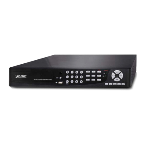
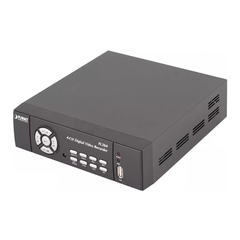
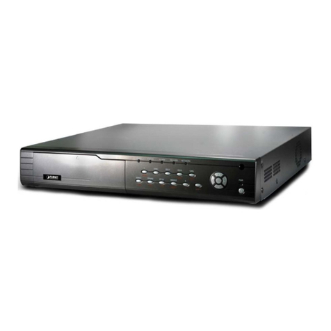
Planet HDVR-1600 User manual

16-Ch Hybrid Digital Video Recorder
HDVR-1600
User’s manual
Version 1.0.0
- 1 -

Copyright
Copyright (C) 2009 PLANET Technology Corp. All rights reserved.
The products and programs described in this User’s Manual are licensed products of PLANET Technology, This
User’s Manual contains proprietary information protected by copyright, and this User’s Manual and all
accompanying hardware, software, and documentation are copyrighted.
No part of this User’s Manual may be copied, photocopied, reproduced, translated, or reduced to any electronic
medium or machine-readable form by any means by electronic or mechanical. Including photocopying, recording,
or information storage and retrieval systems, for any purpose other than the purchaser's personal use, and without
the prior express written permission of PLANET Technology.
Disclaimer
PLANET Technology does not warrant that the hardware will work properly in all environments and applications,
and makes no warranty and representation, either implied or expressed, with respect to the quality, performance,
merchantability, or fitness for a particular purpose.
PLANET has made every effort to ensure that this User’s Manual is accurate; PLANET disclaims liability for any
inaccuracies or omissions that may have occurred.
Information in this User’s Manual is subject to change without notice and does not represent a commitment on the
part of PLANET. PLANET assumes no responsibility for any inaccuracies that may be contained in this User’s
Manual. PLANET makes no commitment to update or keep current the information in this User’s Manual, and
reserves the right to make improvements to this User’s Manual and/or to the products described in this User’s
Manual, at any time without notice.
If you find information in this manual that is incorrect, misleading, or incomplete, we would appreciate your
comments and suggestions.
CE mark Warning
The is a class B device, In a domestic environment, this product may cause radio interference, in which case the
user may be required to take adequate measures.
WEEE Warning
To avoid the potential effects on the environment and human health as a result of the presence of
hazardous substances in electrical and electronic equipment, end users of electrical and electronic
equipment should understand the meaning of the crossed-out wheeled bin symbol. Do not dispose of
WEEE as unsorted municipal waste and have to collect such WEEE separately.
Trademarks
The PLANET logo is a trademark of PLANET Technology. This documentation may refer to numerous hardware
and software products by their trade names. In most, if not all cases, their respective companies claim these
designations as trademarks or registered trademarks.
- 2 -

- 3 -
Revision
User’s Manual for PLANET VoIP Analog Telephone Adapter:
Model: DVR
Rev: 1.0.0 (2009, May)
Part No. EM-HDVR-1600

- 4 -
TABLE OF CONTENTS
Chapter 1...................................................................................................................................7
Introduction ..............................................................................................................................7
Overview.......................................................................................................................................................7
Package Content ..........................................................................................................................................8
Physical Details ............................................................................................................................................8
Front Panel ...........................................................................................................................................8
Rear Panel ............................................................................................................................................9
Chapter 2 Syetem Setup.........................................................................................................11
Physical Installation Requirement............................................................................................................ 11
2.1 Position the Unit................................................................................................................................11
2.2 Select Video Format.......................................................................................................................... 11
2.3 Connect Devices to the Unit ............................................................................................................. 11
2.4 Rear Panel Connectors.....................................................................................................................12
Chapter 3 General System Setup..........................................................................................15
3.1 Front Panel Introduction..................................................................................................................15
3.1.1
LED Definition................................................................................................................15
3.1.2
Functional Keys...............................................................................................................16
3.2 Enter OSD Setup Menu....................................................................................................................18
3.2.1
User Management ...........................................................................................................19
3.3 Power On / Shutdown the Unit........................................................................................................20
3.4 System Date / Time Setting...............................................................................................................20
3.4.1
Set Date / Time................................................................................................................21
3.4.2
Daylight Saving Time......................................................................................................21
3.4.3
Network Time Protocol Setup.........................................................................................22
3.5 IPCamera Setting.............................................................................................................................23
3.5.1
IP Camera Information....................................................................................................23
3.5.2
Connection Setup ............................................................................................................24
3.5.3
Device Setup ...................................................................................................................25
3.5.4
Activated.........................................................................................................................25
3.5.5
Status...............................................................................................................................25
3.6 Record Schedule / Quality Setting...................................................................................................25
3.6.1
Schedule Setup................................................................................................................26
3.6.2
Preset Record Configuration ...........................................................................................26
3.6.3
Per Camera Configuration...............................................................................................27
3.6.4
Record Event Video Only................................................................................................27
3.6.5
ezRecord Setup................................................................................................................27
3.6.6
Data Lifetime...................................................................................................................28
3.6.7
Pre-Alarm Recording ......................................................................................................29

- 5 -
3.6.8
Circular Recording..........................................................................................................29
3.6.9
Audio Recording.............................................................................................................29
3.6.10
Purge Data.......................................................................................................................29
3.7 POS and Text Setup..........................................................................................................................30
3.7.1
Text Function...................................................................................................................30
3.7.2
Text Overlay....................................................................................................................30
3.7.3
Exception Text Setup.......................................................................................................31
3.7.4
Input Setup ......................................................................................................................32
Chapter 4 Basic Operation....................................................................................................34
4.1 View Live / Playback Video..............................................................................................................34
4.1.1
Viewing Modes ...............................................................................................................34
4.1.2
Digital Zoom...................................................................................................................35
4.1.3
View Live Cameras .........................................................................................................35
4.1.4
View Recorded Video......................................................................................................35
4.2 Sequence Setup..................................................................................................................................36
4.2.1
Sequence with Main Monitor (1st and 2nd)....................................................................36
4.2.2
Sequence with Call Monitor............................................................................................36
4.3 Search Recorded Video.....................................................................................................................37
4.3.1
Search by Time................................................................................................................37
4.3.2
Search by Event...............................................................................................................38
4.3.3
Search by Text.................................................................................................................39
4.4 Video Export......................................................................................................................................40
4.4.1
Export from OSD Setup Menu........................................................................................40
4.4.2
Quick Video Export through Front Panel........................................................................42
4.5 Dome Control....................................................................................................................................44
4.5.1
Dome Connection............................................................................................................44
4.5.2
Dome Protocol Setup ......................................................................................................45
4.5.3
RS485 Setup....................................................................................................................45
4.5.4
Dome Controlling Key....................................................................................................46
4.5.5
Set Preset Points..............................................................................................................47
4.5.6
Call Preset Points ............................................................................................................47
4.6 Intercom Function.............................................................................................................................48
4.7 UPnPFunction ..................................................................................................................................48
4.7.1
Setting Up the DVR and the PC......................................................................................49
4.7.2
UPnP NAT Traversal Function........................................................................................49
Chapter 5 Remote Monitoring Software..............................................................................50
5.1 Remote Monitoring System Requirements.....................................................................................50
5.2 Software Installation.........................................................................................................................51
5.2.1
Change Internet Settings .................................................................................................51
5.2.2
Install Remote Monitoring Software...............................................................................52
- 6 -
5.3 Basic Operation for Monitoring Remotely .....................................................................................55
5.3.1
View Live Video..............................................................................................................55
5.3.2
Instant Recording ............................................................................................................56
5.3.3
Playback Video................................................................................................................57
5.3.4
Verify Digital Signature...................................................................................................59
5.3.5
Search from Event List....................................................................................................59
5.3.6
Take a Snapshot...............................................................................................................59
5.3.7
Remote Monitoring Software Trouble Shooting Guide...................................................59
Appendix A: Recommended HDDs ..........................................................................................................61
Appendix B: Remote Controller...............................................................................................................62
Appendix C: USB Mouse Operation........................................................................................................64
Appendix D: KeyboardAccess Sketch.....................................................................................................65
Appendix E: Simultaneous Output Options............................................................................................66
Appendix F: Jog / Shuttle Control............................................................................................................67
Appendix G: IPCamera Installation........................................................................................................68
Appendix H: HDVR Specifications..........................................................................................................72

11
Chapter 1
Introduction
Overview
The existing traditional CCTV surveillance system is gradually upgraded to packet switching TCP/IP network
as the broadband communication becomes more and more popular. To efficiently build the surveillance system
with the existing analog cameras and IP cameras, PLANET provides the best Hybrid DVR solution,
HDVR-1600, which can support analog cameras and IP cameras simultaneously or obtains the video signal
from 8 IP cameras as a pure NVR. The HDVR-1600 is designed as a professional security device supporting
video data recording, remote surveillance over a secure IP network and viewing / recording / playback at the
same time in the full-time security application.
The HDVR-1600 supports USB keyboard and mouse to bring users much easier operation. Moreover, the
remote software – Central Management Software (CMS) provides distant accessibility for remote system
control.
For various surveillance applications via RS-485 interface, the HDVR-1600 has integrated control keyboard
that provides another control interface. Not only control HDVR-1600, but also capability to control most types
of PTZ protocols, and even more convenience to control them via to expand the Control Keyboard:
HDVR-KB100 / HDVR-KB200 / HDVR-KB300. With integrated alarm I/O, it can detect record and ring a siren.
The HDVR-1600 can also do motion detection / schedule recording to complete surveillance plans.
Furthermore, it supports hardware Watch-Dog function to monitor the DVR healthy status and will restart the
DVR to prevent the system hangs when the system is detected unstable.
The HDVR-1600 has supports the total recording frame rates to 60 fps (NTSC) at H.264 @ D1 format, and the
user could install the extension card to expand it up to 240 (HDVR-15) / 480 (HDVR-30) fps at H.264 @ D1
format.
Securing the content stored on hard-disk of the digital video recorder systems and providing conditional
access to stored content management, PLANET HDVR-1600 Hybrid Digital Video Recorder offers a perfect
solution for both security professionals and business owners who require the unparalleled flexibility and
reliability in IP surveillance field.
Product Features
•Multi-Codec for H.264 / MPEG-4 / MJPEG compression
•Mega-Pixel recording
•Multiple video output ports
•Supports up to 4 SATA devices
- 7 -

•POS Function: transaction monitoring
•NTP for time synchronization
•Easy configuration interface with USB Keyboard / Mouse
•Multi-Tasking: Recording, Display, Backup, Playback
•CMS manage up to 512 Channels
•Calendar, Time and Event search
•Support multiple languages
Package Content
The contents of your product should contain the following items:
HDVR-1600
Quick installation guide
User’s manual CD
Power cord
HDD Bracket x 4
Key x 2
SATA cable x 2
Remote Controller
Mounting Kit
Physical Details
Front Panel
Front Panel of HDVR-1600
Item Description
1 USB 2.0 Port The USB 2.0 port allows users to connect an external USB device to
the unit, such as a USB ThumbDrive© or a USB mouse.
2 Channels
1. In Live and Playback modes, press any key to view the
corresponding video in full-screen.
2. In input interface, 1~10 can be used for direct input of numbers 0~9.
3. In Dome Camera Control mode, 1 is for entering the Set/ Go preset
- 8 -

menu; 2 is for hiding or displaying the dome setting parameters;
11~16 is for quick access of preset points 1~6.
3 Power LED It lights up when power source is connected.
4 Network LED It lights up when network is connected. In addition, it blinks when data is
being transmitted via the network.
5 Alarm LED It lights up when an alarm is triggered.
6 Record LED It blinks when videos are being recorded.
7 HDD LED It lights up when data is processed to or from the connected HDD(s).
8 MODE Press this key to view in full-screen or multiple window modes.
9 PLAY/STOP Press once to start the playback of recorded video. Press again to exit.
10 FREEZE Press this key to freeze the current viewing screen.
11 SEQ Press this key to start automatic sequence display of cameras.
12 ESC Press this key to cancel or exit from certain control mode.
13 Direction Keys
1. In Zoom mode, these keys function as normal direction keys.
2. In the OSD setup menu, the direction keys are used to move the
cursor to previous or next fields. To change the value in the selected
field, press UP / DOWN keys.
14 ENTER
1. In OSD menu or selection interface, press these key to make the
selection or save settings.
2. In live full-screen viewing mode, press this key to view a 2× zoom
image; press it again to return.
15 Shuttle/ Jog This is used to control playback operations.
16 DOME Press this key to enter Dome Camera Control mode.
17 CALL Press this key to control call monitor or 2nd main monitor.
18 COPY This key is used for marking time in quick video export function.
19 SEARCH Press this key to search recorded video by date/time or event.
20 MENU Press this key to enter the OSD setup menu.
Rear Panel
Rear Panel of HDVR-1600
Item Description
1 Main Monitor
Audio Out
A RCA connector is provided to output audio associated with the main
monitor.
2 Main Monitor (BNC) A BNC connector is provided for connecting to a main monitor.
3 Call Monitor (BNC) A BNC connector is provided for connecting to a call monitor.
- 9 -

- 10 -
4 Video In (BNC)
A group of BNC connectors is offered for video input streams from
installed cameras. The number of connectors equals to the number of
channels.
5 Video Out (BNC) The same amount of BNC connectors underneath Video IN (BNC) is
offered for looping out the video input.
6 Main Monitor (S-Video) An S-Video connector is provided for connecting to a main monitor.
7 Audio In The DVR provides audio in connectors (a terminal block) for each
channel to connect its individual audio source device.
8 Main Monitor
(Digital Output)
A digital output connector is provided for connection to a displaying
device that transfers data digitally to show the best video quality.
9 Main Monitor
(VGA)
A VGA output connector is offered for connecting to a VGA main
monitor.
10 Alarm I/O & RS-485 The DVR provides alarm I/O and RS-485 ports that offer users the
flexibility required to connect the unit to other devices.
11 NAS Device (*1) The NAS connector allows users to connect to a Network-Attached
Storage (NAS) device to expand HDD capacity of the DVR.
12 USB 2.0 Ports (×2)
Two USB 2.0 ports are located on the rear panel for users to connect
external USB devices to the unit, such as ThumbDrive® or a USB
mouse.
13 LAN 10/100/1000M
(RJ-45)
The DVR is capable of networking and it allows the videos to be viewed
over the LAN network or the Internet by using the Internet Explorer.
14 RS232 The DVR provides a RS232 communication port for sending and
receiving signals.
15 Audio Out (Optional) Optional Audio Out connectors can be installed for each channel to
connect its individual audio output device.
16 Power Switch Use this switch to power on / off the DVR.
17 Power Jack Connect the power supply cord shipped with the DVR. Use of other
power supply cords may cause overloading.
*1 : This feature will available in the future.

2
Chapter 2
Syetem Setup
Physical Installation Requirement
The notices and introduction on system installation will be described particularly in this chapter. Please follow
the description to operate the unit.
In order to prevent the unit from data loss and system damage that caused by a sudden power fluctuation, use
of an Uninterruptible Power Supply (UPS) is highly recommended.
2.1 Position the Unit
Firstly, note to position / mount the DVR in a proper place and be sure to power off the unit before making
any connections. The placed location should avoid hindering or blocking the unit from airflow. Enough airflow
is needed to protect the unit from overheating. The maximum allowable temperature of operating environment
is 40°C.
The unit utilizes heat-conducting techniques to transfer internal heat to the case, especially to the bottom side
of the unit.
NOTE: Be sure the rubber feet are not removed, and always leave a space for air ventilation on
the unit’s bottom side.
2.2 Select Video Format
2.3 Connect Devices to the Unit
This section lists some notices that should be given before making any connections to the DVR.
Connecting Required Devices
Before powering on the unit, cameras and a main monitor should be connected to the unit for basic
operation. If needed, connect a call monitor for displaying full screen video of all installed cameras in
sequence.
Connecting Short-term Device
- 11 -
If any short-term devices shall be installed to the DVR as parts of the unit system, such as USB
ThumbDrive®or any USB devices, etc., make sure those devices are connected only after the unit is powered
on. The reason is because the DVR can recognize the external devices only after the power-on process is
done completely.

2.4 Rear Panel Connectors
There are various connectors on the rear panel for the DVR installations. The connectors are described
as the followings.
Main Monitor (S-Video / BNC)
Both S-Video and BNC output connectors are offered for connection to a
main monitor. The main monitor displays live image and playback
recorded video in full-screen or split-window format.
Call Monitor (BNC)
The call monitor is used to display full screen video of all installed cameras in sequence. The BNC call
monitor connector allows user to connect the DVR with a call monitor.
VGA Output
VGA output connectors are offered for connecting to VGA main
monitors. Some models provide one while other models provide
two VGA connectors.
Dual VGA
VGA +
Digital Output
Digital Output
A digital output connector is provided for connection to a displaying device that transfers data digitally to
show the best video quality.
NOTE: Refer to Appendix E: Simultaneous Output Optionsfor detailed information about
monitor functionality.
- 12 -

Video Input
A group of BNC connectors is offered for video input streams
from installed cameras. The number of connectors is equal to
the number of channels.
Video Out
Plenty of BNC connectors are positioned on the rear panel for looping out the video input.
RS-232C
The unit provides a RS-232C communication port for sending
and receiving signals.
Alarm I/O & RS485
The unit provides alarm I/O and RS-485 ports that offer users
the flexibility required to connect the unit to the other device.
The definition for pins varies when the DVRs have different
channels. Refer to the belows for detailed pin definitions.
Pin Definition Pin Definition Pin Definition Pin Definition
1 RS485 D+ 9 Common Node B 17 Alarm In 1 25 Alarm In 9
2 RS485 D−10 Normal Open B 18 Alarm In 2 26 Alarm In 10
3 Ground 11 Ground 19 Alarm In 3 27 Alarm In 11
4 Normal Close A 12 Normal Close C 20 Alarm In 4 28 Alarm In 12
5 Common Node A 13 Common Node C 21 Alarm In 5 29 Alarm In 13
6 Normal Open A 14 Normal Open C 22 Alarm In 6 30 Alarm In 14
7 Ground 15 Ground 23 Alarm In 7 31 Alarm In 15
8 Normal Close B 16 Ground 24 Alarm In 8 32 Alarm In 16
NAS
The NAS connector allows users to connect a Network Attached Storage (NAS)
device to expend HDD capacity of the DVR.
NOTE: This feature will available in the future.
LAN 10/100/1000M (RJ-45)
The DVR is capable of networking and it allows the videos to be viewed over the
LAN network or the Internet by using the Internet Explorer.
USB Connector (x2)
There are two USB2.0 ports on the rear panel for users to connect external USB
devices to the unit, such as ThumbDrive®, DVD+RW, or a USB mouse.
- 13 -

Audio Out (Optional)
The DVR provides two types of connectors for connection to audio
output devices, such as amplified speakers. One is a RCA
connector to output audio associated with the main monitor. The
other is an optional terminal block providing connections with all
channels for the purpose of two-way audio talk function. Pins on
the upper row are Audio Out connectors for all channels, in
sequential order from left to right. All other pins on the bottom
row are for ground connection.
Audio In
A terminal block titled “AUDIO IN” provides connections to audio
source devices of all channels for the purposes of audio recording
and two-way audio talk function as well. Pins on the upper row are
Audio In connectors for all channels, in sequential order from left to
right. All other pins on the bottom row are for ground connection.
Power Switch
Use this switch to power on or shutdown the DVR.
Power Jack
Connect the power supply cord shipped with the DVR.
NOTE: Use of other power supply cords may cause overloading.
- 14 -

3
Chapter 3
General System Setup
Before operating the DVR, some general configuration should be setup first. The following
subsections will introduce function keys on the front panel and general configuration of the DVR.
The regular displayed OSD information and its displayed positions are shown as following figure.
Title of the channel will be displayed on the top-left corner of the window, either in full screen mode or in
multiple channel mode. The current operating mode, including Call mode, Dome Control mode,
Playback mode, Freeze mode and Sequence mode, will be displayed on the bottom-left corner of the
screen. The date/ time information will be display on the bottom-right corner of the screen.
Ch4
►*1
2008/11/09 PM04:31:22
3.1 Front Panel Introduction
The front panel controls enable users to control the unit and preset the programmable functions.
3.1.1 LED Definition
The LEDs on the front panel of the DVR are described as follows.
Power LED
The LED lights up when the correct power is connected to the unit.
Network LED
The LED lights up when the DVR is connected to a network and
blinks when data is being transferred.
REC LED
The LED blinks while the DVR is recording.
Alarm LED
The LED lights up when an alarm is triggered.
- 15 -

HDD LED
The LED lights up while the HDD is processing data to or from the
connected HDD.
3.1.2 Functional Keys
This section describes the functional keys, which are for normal operation, on the front panel
of the DVR.
CHANNEL
•In both Live and Playback modes, press the CHANNEL key to view the corresponding video
in full screen. The number of the CHANNEL keys corresponds to the number of cameras
supported by the unit.
•In Dome Control mode, the key “1” is used to access the Set/Go preset menu; the key “2” is
used to hide or display the dome camera setting parameters.
COPY
In Playback mode, press COPY to select the start and end time of the export video. Refer to
section Video Export for detailed information.
CALL
•In Live mode, press this key once to control the call monitor. Alternatively, press and hold this
key for 3 seconds to control the 2nd main monitor.
•In Dome Control mode, press CALL in association with ENTER to enter the OSD setup menu
of the dome camera.
DOME
Press the key to enter Dome Control mode. Please refer to Section Dome Control for
detailed controlling operation.
MODE
Press repeatedly to select desired main monitor display format. There are four available view
modes: full screen, 4-window (2×2), 9-windows (3x3) and 16-window (4×4). Refer to section
Viewing Modes for detailed information.
PLAY
Press this key to switch between live image and playback video.
NOTE: The video of latest 5 ~ 10 minutes cannot be played back because the video is
still saved in the buffer.
- 16 -

FREEZE
•Press FREEZE while viewing live image, the live video will be frozen. The date / time
information shown on the monitor will continue updating, as well as the recording of video.
Press FREEZE again to return to live mode.
•Press FREEZE while playing the recorded video, the playback video will be paused. Press
LEFT / RIGHT to move the recorded video reverse / forward by single step. Press FREEZE
again to continue playing video.
SEQ (Sequence)
Press to start automatic sequence display of video from all installed cameras.
MENU
Press this key to enter the OSD setup menu.
SEARCH
In both Playback and Live mode, press SEARCH to enter the Search menu for searching
and playing back recorded video by date / time, event, or text.
Direction Keys
•In Zoom mode, these keys function as Direction keys.
•In the OSD setup menu, the LEFT / RIGHT keys are used to move the cursor to previous or
next fields. To change the value in the selected field, press UP / DOWN keys.
ENTER / ZOOM
•In OSD setup menu or selection interface, press this key to make the selection or save
settings.
•In live full screen viewing mode, press this key to view a 2× zoom image; press it again to
return.
ESC
•Press to cancel or exit from certain mode or OSD setup menu without changing the settings
made previously.
•If the password protection has been enabled, press ESC for five seconds to lock up the
function of certain keys, including PLAY, MENU, SEARCH, and DOME. Once users lock up
the function of these keys, correct password must be entered before accessing the functions
of these keys.
NOTE: Please go to the <Password> menu to enable or disable the password
protection.
- 17 -

JOG/ SHUTTLE (for specified models)
The jog/shuttle knob, shown as the figure on the right, is a
combination of a shuttle ring with an embedded jog disk. It
provides wide latitude in playback control. Note that the
jog/shuttle knob is active only when the DVR is in Playback
mode.
Please refer to Appendix F: Jog / Shuttle Control for further
information.
3.2 Enter OSD Setup Menu
The configuration of the DVR can be customized by entering the intuitive Graphical User Interface
(GUI) OSD setup menu. Collaborating with a USB mouse, setting up the DVR can be easy as operating
on a PC. Press MENU and input a valid username. A preset username “admin” can be inputted via
pressing the hot key MENU. Move to <OK> and press ENTER to proceed.
Input Username
A B C D E F G H I J K L M
N O P Q R S T U V W X Y Z
a b c d e f g h i j k l m
n o p q r s t u v w x y z
0123456789 .!@
# −_,“+=*
◄ ► Backspace Delete
Cancel OK
The next step is to enter a corresponding password. The preset password for “admin” is “1234”.
Password Verification
_______
Press Channel Keys To Enter Password
(4-8 Digits)
Press ◄Key To Delete
NOTE: It is strongly suggested to change the preset password to prevent unauthorized
access to the unit.
An icon displayed at the center-bottom of the screen will show the authority level of the
account. Under logout condition, the icon will show “N”. When an account is logged in, its
authority level number (1~8) will be shown.
- 18 -

Before completely logout, other functions can also be accessed without having to login again.
There is two way to logout: manually logout by pressing ESC key at Live mode, or auto logout
when keys are not pressed for 5 minutes at Live/ Menu mode.
3.2.1 User Management
The DVR provides the option to create up to seven sets of usernames and passwords with
customized authority, excluding the preset “admin” account. From the Main Menu, select <System
Setup> Æ<User Management> and the menu is as the following:
User Management
1. Password Protection
2. Account Setup
3. Authority Setup
4. Load Default Setting
ON
No
Password Protection
Select <ON> to request for username and password for accessing functions listed in
Authority Setup menu, or select <OFF> to allow free access.
Account Setup
Setup customized username, password, and authority level in this menu. The username is
case sensitive. The authority level rank from level 1~8, and level 8 has highest authority.
Alternatively, select <Disable> to stop using the account.
NOTE: The username and authority level of the preset “admin” account cannot be
changed.
Authority Setup
Setup the allowed authority level for accessing the functions listed in this menu. The
functions include: Playback/Search, Dome Control, Call Control, Export Data, Menu Access,
System Setup, Monitor Setup, Camera Setup, Record Setup, Sequence Setup, Event Setup,
Database Setup, Configuration, Text Setup, and Shutdown. The authority level rank from level
1~8, and level 8 has highest authority. Alternatively, select <Disable> to allow free access.
NOTE: The “Menu Access” cannot be set to <Disable>.
When the account does not have authority to access certain functions, an error message will
be displayed on the screen.
Load Default Setting
Select <Yes> to load the default setting.
- 19 -

- 20 -
3.3 Power On / Shutdown the Unit
If the DVR must be shutdown for any reason, please use the proper shutdown and power on
procedures to avoid damaging the DVR.
To Power On the Unit:
Check the type of power source before plug in the power cord to the DVR (the acceptable
power input is between AC110V ~ AC240V), and power on the unit using the power switch on the
rear panel.
The color bar and system checking information will be shown on the monitor and then
disappear when the unit has been completely powered up.
To Restart / Shutdown the Unit:
Press MENU and input the username and password that has sufficient authority to access
the OSD setup menu. Select <Shutdown> in Main Menu and press ENTER to enter the Shutdown
menu, which displays as follows.
Shutdown
1. Power Off
2. Reboot
Execute
Execute
Power Off
Select this item to shut down the unit. Do not remove the power during shut down until the
message “You can safely turn off DVR now!” displays.
Reboot
Select this item to reboot the unit. The color bar and system checking information are
displayed on the monitor until the unit is completely restarted.
3.4 System Date / Time Setting
Users can set the current date, time and other OSD parameters in Date/Time menu (under
System Setup menu). The login account should have authority to access the System Setup menu.
In OSD setup menu, select <System Setup> and press ENTER, then select <Date/Time> to
access the Date/Time menu; the menu displays as follows.
Date/Time
1. Date
2. Time
3. Time Zone
4. Date/Time Display
5. Date Display Mode
6. Time Display Mode
7. Date/Time Order
8. Daylight Saving Time Setup
9. Network Time Protocol Setup
2008/02/21
PM10:39:26
OFF
1 Row
Y/M/D
24 HR
Date First
Other manuals for HDVR-1600
1
Table of contents
Other Planet DVR manuals

Planet
Planet NVR-401 User manual

Planet
Planet DVR-450 User manual

Planet
Planet NVR-3210 User manual

Planet
Planet DVR-860 User manual

Planet
Planet DVR-471 User manual

Planet
Planet HDVR-430 Mounting instructions

Planet
Planet DVR-462 User manual

Planet
Planet DVR-460 User manual

Planet
Planet DVR-471 User manual

Planet
Planet DVR-461 User manual

Planet
Planet DVR-1670 User manual

Planet
Planet NVR-915 User manual

Planet
Planet NVR-820 User manual

Planet
Planet DVR-460 User manual

Planet
Planet DVR-461 User manual

Planet
Planet DVR-460 User manual

Planet
Planet HDVR-430 User manual

Planet
Planet DVR-1650 User manual

Planet
Planet DVR-872 User manual

Planet
Planet DVR-860 User manual