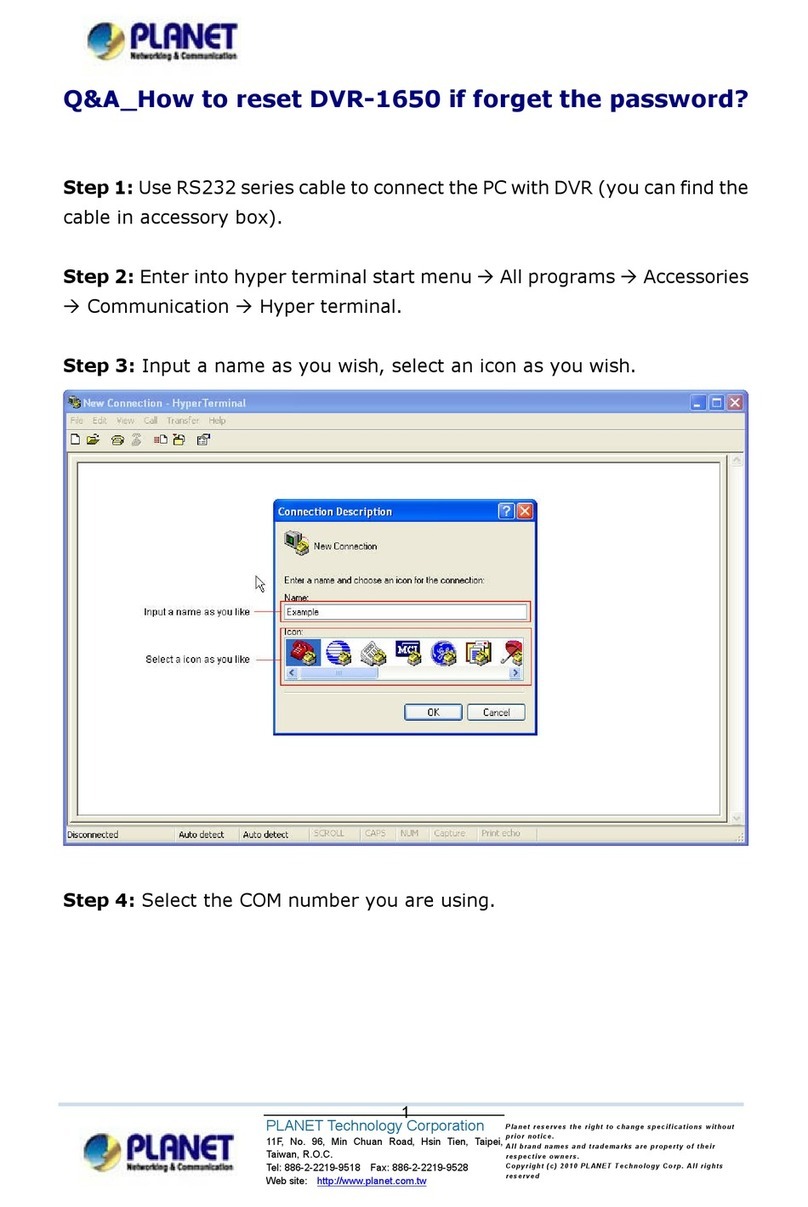
Planet DVR-1650 User manual

1
Triplex Digital Video Recorder
DVR-1650
User smanual

2
Copyright
Copyright(C)2005PLANETTechnologyCorp.All rightsreserved.
Theproductsand programsdescribedinthisUser sManualarelicensedproductsofPLANETTechnology,ThisUsers
Manualcontainsproprietaryinformationprotectedbycopyright,andthisUsersManualand allaccompanyinghardware,
software, anddocumentationarecopyrighted.
Nopart ofthisUser sManual maybecopied, photocopied,reproduced,translated, orreducedtoanyelectronicmedium
ormachine-readableform byany means by electronicor mechanical.Includingphotocopying,recording,or information
storageandretrievalsystems,for any purposeotherthan thepurchaser'spersonaluse,and withouttheprior express
writtenpermission ofPLANETTechnology.
Disclaimer
PLANETTechnologydoesnotwarrantthatthehardwarewill workproperlyinallenvironmentsandapplications, and
makesnowarrantyandrepresentation,eitherimpliedorexpressed, withrespect tothequality,performance,
merchantability, orfitness foraparticular purpose.
PLANEThasmadeeveryeffort toensurethatthisUser sManualisaccurate;PLANETdisclaimsliabilityfor any
inaccuraciesoromissionsthatmayhaveoccurred.
InformationinthisUser sManual issubjecttochangewithoutnoticeanddoesnotrepresent acommitment onthepartof
PLANET. PLANETassumesno responsibilityforanyinaccuraciesthatmaybecontainedinthisUsersManual.PLANET
makesnocommitmenttoupdateorkeepcurrenttheinformation inthisUsersManual, and reservestherighttomake
improvementstothisUser sManualand/ortotheproductsdescribedinthisUsersManual, atanytimewithout notice.
Ifyoufindinformationinthismanual thatisincorrect, misleading,or incomplete, wewouldappreciateyourcommentsand
suggestions.
CEmarkWarning
TheisaclassBdevice,Inadomesticenvironment, thisproductmaycauseradiointerference,inwhich casetheusermay
berequiredtotakeadequatemeasures.
WEEE Warning
Toavoidthepotential effectson theenvironment andhumanhealthas aresultofthepresenceofhazardous
substancesinelectricalandelectronicequipment,end usersof electricalandelectronicequipmentshould
understand themeaningof thecrossed-out wheeledbinsymbol. Donot disposeofWEEE asunsorted
municipalwasteand havetocollectsuchWEEEseparately.
Trademarks
ThePLANETlogoisatrademarkofPLANETTechnology.Thisdocumentationmayrefertonumeroushardwareand
softwareproductsby theirtradenames. Inmost, ifnotallcases,theirrespectivecompaniesclaim thesedesignationsas
trademarksorregisteredtrademarks.
Revision
User sManualforPLANETTriplex DigitalVideoRecorder
Model: DVR-1650
Rev: 1.0(Oct. 2005)
PartNo.EM-DVR1650V1
3
Table of Contents
Chapter1Introduction....................................................................................1
Overview.......................................................................................................................1
DVRFunctions................................................................................................................1
Package Content..........................................................................................................2
Physical Details............................................................................................................2
ButtonsDefinitions..........................................................................................................3
PhysicalInterfaces...........................................................................................................5
Chapter2DVR-1650Menu Setup................................................................10
Introduction................................................................................................................10
MenuTree......................................................................................................................11
MAINMENU...............................................................................................................12
SYSTEMSETUP..........................................................................................................13
DISPLAYSETUP.........................................................................................................16
RECORDING SETUP...................................................................................................18
ALARMSETUP...........................................................................................................19
MOTION SETUP..........................................................................................................21
WEEKLYSCHEDULE.................................................................................................23
NETWORKSETUP......................................................................................................25
ARCHIVING................................................................................................................27
Playback archived videofiles........................................................................................28
HDD INFORMATION..................................................................................................30
PLAYBACK Configurations.......................................................................................32
SearchList....................................................................................................................32
Displaymode..............................................................................................................34
Recordingmode.........................................................................................................36
Playback mode...........................................................................................................37
PTZ control Procedure..............................................................................................38
Chapter3Utility Administration...................................................................39
NetViewerutility.........................................................................................................39
ProceduresofDVRClientutility...................................................................................39
AppendixAPinDescriptionof connectors.................................................63
AppendixB SoftwareUpgradeProcedure..................................................65
AppendixC Specification..............................................................................68

1
Chapter1
Introduction
Overview
The DVR-1650 (TriplexDigitalVideo Recorder) isforrecording/playback/Network video streamsfromup to16
channelsat the sametime.Itadoptscutting-edge digitalimage compression technologytocompress the
analog inputchannelvideo streams, and usesHDD torecordthe compressed video stream.
The following operation guide explainshowtooperate/manage the DVR-1650,and the following installation
guide explainshowtocompletethe first DVR-1650 installation on yourside.
DVR Functions
ThisDVRprovidesrecording capabilitiesfor16 camerainputs. It providesplayback orlivedisplayand
network function whileinrecording mode.Andit alsooffersthe following features:
•Real-time recording forupto16 analog cameras,maximumupto60 NTSCIPS(Imageper second),
50 PALImages per Second
•SimultaneouslyRecord, Playback and Network viewing
•RemotemonitoringviaInternetExplorer orbundledutility
•Converttraditional surveillance equipmentintodigitalized surveillancenetwork
•Localmonitoring,no specialequipmentrequired
•Display andRecord Video Resolution:NTSC(720x480), PAL(720x576)
•1channel audiorecording
•Loop-Through videoconnectorstosecondary monitordevice
•Built-inbuzzer alarm tosendwarningwhenalarm ormotionhas beentriggered
.
•USBinterface formachinearchiving
•PowerfulSearch Engines(Schedule/Motion/ Alarm/ Manualrecording searchorbyDate/Time
•Bundledrecording andplayback utilityforremotecomputer
•DDNS/ DHCPclientsupport
1

2
PackageContent
The contentsof yourproductshouldcontainthefollowing items:
lDVR-1650
lPoweradapter
lRack Mount Bracket
lQuickInstallation Guide
lUserManualCD
lRemotecontroller
Physical Details
Overviewoffrontpaneland rearpanel
USBMemory
Drive
Monitor &Spot Speaker
Microphone
Alarm
Output
Sensor
Input
Ethernet
cable
Cameras
RS485
(PTZcontroller)
•••••Loop Through
for 16chout
75 Ohm
Terminator
Adaptor
(12V)
RemoteController

3
Buttons Definitions
1. USBport
AUSBportisprovided toconnectexternal USB memorydriveforbackup video.
NOTE: Allworking functionsofDVRwillstop whileUSB portisinuse.
2. Video Display ChannelSelectionbuttons
Channel button fromCH1 toCH16 istoselect videochanneldisplayed on monitor.
3. ChannelDisplay modeselectionbuttons
Therearefourkindsofvideo displaymodeswhichconsistsofsequential display,QUAD, 9CH, 16CH
displaymode.
FullPictureDisplaymode:Fullpicturecan be selected bychannelselection button fromCH1 toCH16.
SequentialDisplay mode:
Ifthisbutton ispressed undergiven video displaymode, eachvideo displaymode isswitched
sequentially.Forexample,if thisbutton ispressed inQUADmode,QUADpictureisswitched
sequentiallyfromCH1-4, CH5-8toCH13-16.
QUADDisplay mode:
IfQUADbutton ispressed, QUADpicturewillbedisplayed.Wheneverthisbutton ispressed,
QUADpictureincluding CH1toCH4,CH5 toCH8, CH9toCH12 and CH13 toCh16 willbe changed in
turn.
9Picture Display mode:
If9picturedisplaybutton ispressed initially,9picturesof CH1 toCH9 willbe displayed.The
coming 9pictureofCH8toCH16 willbe displayed bypressing thisbutton one more.Wheneverthis
button ispressed, 9picturesset isswitched inturn.
1
2
3
4
5
6
7
8
9
11
10
12
14
13
15
16

4
16 Picture Displaymode:
Whenever16 picturedisplaybutton ispressed, picturedisplaymode willbe changed from16
pictureset displayto1(large)+7(small)set displaymodeand 2(large)+8(small)set displaymode.
4. FUNCTION
The largerpicturedisplaymode in1(large)+7(small),2(large)+8(small)set displaymode can be
changed bythe combination ofFUNCTIONand channelselection button.Whileinthe 1(large)+7(small),
2(large)+ 8(small)set displaymodes, press FUNCTIONbutton firstthen press channelbuttonsfromCH1 to
CH16, ex: CH2.The largerpicturewillchange tothe pressed channelnumber,CH1àCH2.
NOTE: Thisfunction isdoing onceafterpressing FUNCTIONbutton.
5. KEYLOCK
Inorderforonlyauthorized person tooperatebuttonsinfrontpanel,thisbutton can be utilized.Ifthisbutton is
pressed, all of buttonsinfrontpanelarenotoperated withyellowLOCKLED. ToreleaseKEYLOCKbutton,
passwordwill be requested just afterpressing LOCKbutton.Ifcorrectpasswordisinput, button LOCKwillbe
released.
6.Archivingbutton
Whenever ARCHIVING button ispressed, archivingwillbe started.
NOTE: PleasemakesureUSBdeviceisplugintoUSBport whilepressing thisbutton.
7. RECbutton
Press REC(Red circle) tostart torecord.Thisistogglebutton.Press RECtostop recording again.
8. RR ( )
Press REWtoperformhigh speed backwardplayback. It supports2to16 timesplayback speed.
9.PLAYbutton (▶)and 10.STOPbutton
If PLAY (▶ )ispressed, searchlistswill bedisplayed on monitor.Afterselectingone recorded fileamong lists,
playback will be started by PLAY button.Tostop playback, STOP buttonisused.WhileDVRisinhigh speed
playback mode likeFForREW, itreturnstonormalplayback byPLAY button.
11. FF (▶▶)
Press FF toperformhigh speed forwardplayback.It support 2to32 timesplayback speed.
12. PAUSE
Press PAUSEtopauseplayback.ThisPAUSEbutton can beused forbackwardorforwardmovementby
one field.The direction offieldmovementisdecided bypressing FF orREWpreviously.

5
13. MENU
Press MENU button toentermenu system.
14. ESC
ESC button isused toreturntouppermenuand tosaveset up parameteratthe sametime
15. Directionbutton andEnter Button
Direction buttonsareused tomoveLEFT, RIGHT,UPand DOWNinmenu.Theyalsocan be used to
input password. ENTERbutton isused tosaveparametersettingsand toselectparametersinthe menu.
Whileinplayback theyareused toselectone oflisted fileforplaybackaftersearching recorded files(use
all,time, alarm,motion, manual sorting moethod and soon).
16 LEDIndicators
1)POWERLED
ThisLEDturns“ON”when poweris “ON”.
2)NETWORKLED
ThisLEDwillturn“ON”, whiledatacommunication isworking through network.
3)ArchivingLED
ThisLEDwillturn“ON”, whiledataarchivingisworking through USB Memory driver.
4)REC
ThisLEDwillturn “ON”during recording.
5)EXT:
ThisLEDwillturn“ON”, when externalalarmsaretriggered ormotionsaredetected.
6)LOCK
ThisLEDwillturn“ON”whileLOCKbuttonisworking.
7)IRReceiver
Remotecontrollersensorinput window
Physical Interfaces
POWER
NETWORK
USBArchiving
REC
EXT
LOCK
IR receiver

6
1. VideoInput: 16channelcompositevideo inputswithBNC connectors
SincethisDVRautomaticallydetectsvideo format(NTSCorPAL)assoon aspoweris
ON, NTSCorPALvideo sourcescan be connectedinDVR. But NTSCand PALvideo sourcesfor16CH
video inputscan not be mixed.If theyaremixed, DVRcan not be operated properly.
2. VideoOutput
One video output (UpperBNC)isused tomonitorlive,playbackpictures.The other
(lowerBNC)isused tomonitorSPOTmonitoringwhichdisplaysallofconnected video channels
sequentially.
3.Audioinput(upper RCA)andOutput(Lower RCA)
Unbalanced audiosignalinput and output withRCAjack.Connect the audiosource(microphone)to
audioinput, audiooutput (speaker) toyouramplifierbecausethe DVRdoesnot haveamplifiedaudio
output, therefore, aspeakerwillbe needed foraudioplayback.The audioinputcan be froman amplified
sourceordirectlyfromamicrophone.
4. 16CH Loop throughoutputs: 16 channelcompositevideo outputswithD-SUBconnectors. If the
connection of loop-through video outputsintovideo equipmentsisrequested, 16CH Loop-Through
outputscan be utilized forit.Ifloop-through video outputswillbe connected toanothervideo equipments,
75 Ohmterminationswitchshouldbe “OFF”. Then, anothervideo equipmentsshouldbe 75 ohm
terminated.
5. 75 OhmTerminationSwitch
If you want toconnect loop-through video outputsintoanothervideo equipments, 75 Ohmtermination
switchshouldbe “OFF”.Then, the othervideo equipmentsshouldbe 75 ohmterminated.Ifloop through
video outputsarenot connected tothe othervideoequipments,it shouldbe “ON”.
If 75 Ohmterminationswitch “ON”or “OFF”ischanged unintentionally,it will causepoorvideo quality.
6.Alarm inputandrelay output: (16 alarminputsand 4relayoutput withNO, NC)
Tomakesecureconnectionson the AlarmConnectorBox,press and holdthe button then insert thewire
1
2
3
5
6
7
8
9
4

7
of alarminthe holebelowofconnectorpin.Afterreleasing the pin,pullgentlyonthe wiretotestitis
connected securely.Todisconnect awire, press and holdtheconnectorpinabovethe wireand pullout
the wire.
16 Alarm Inputs: 1,2,3,4,…, 16,G (Ground)
You can useexternal devicestosignalthe DVRresponding toevents. Mechanicalorelectrical switches
can be wired tothe AlarmInputsand GND (Ground)connectors.The thresholdvoltage is4.3Vand should
be stableat least 0.5secondstobe detected.
G (Ground), COM (common):Gissameascommon.
Connect the ground side of theAlarminputtoG (Ground). Connect the ground side of relayoutputto
COMconnector.
4Relay output:
4relayoutputswithNO orNCcan be sent toexternaldevice.You can select NOorNCaccording to
characteristicofmechanicalorelectrical switch.
7. EthernetPort:
Connect aCat5cablewithan RJ-45 jacktothe DVRconnector.Remotecomputerviewervianetwork to
liveviewing orsearching.
8. RS485:Forcamerapan and tilting control
ThisDVRcan be controlled remotelybyremotePCsoftware.The RS485 connector
can be used tocontrolPTZ(pan, tilt, zoom)cameras. Connect RX+, RX-ofthe
controlsystemtothe TX+, TX-(respectively)ofthe DVR.
9.Power Input(fromAdapter)
Connect the adaptortothe DVRforDC powersupply.
RemoteController
ë
Note Currently PTZ camera support: Panasonic/ Pelco-
D/ PelcoP/
Techwin/ Niko/ DRX502A_DSC230s /KRE_301_302/
GC_755_NP/
TOA_CC554/ RAS716LS / LPT-100 / KD.

8
<ButtomDescription>
1RECStart /Stop recording button
2USB Start archivingbutton
31,2,3,…0,+10 Video channelselection buttons
(1,2,3,4isdesigned forpasswordinput
aswell)
4F1Function key.
5ESCExit touppermenu
6MENU Entermenu mode
7 1)UP(▲)
2)DOWN(▼)
LEFT/RIGHTbutton tomove
UP/DOWNbutton tochange ENTER
3
6
9
12
2
1
4
5
7
8
10
11
13
14

9
3)LEFT( )
4)RIGHT(▶)
5)ENGER
toconfirmsettings.
8STOPStop playbackbutton
9Search/ PLAYStart playback orsearcheventlist
button
10 FF,REWFast Playbackbuttons
11Forward/backwardby1fieldPAUSE/1fieldmovementbackward
PAUSE/1fieldmovement forward
12 Video PictureDisplaymode 1)Sequential displaybutton
2)QUADdisplaybutton
3)9picturedisplaybutton
4)16/8/10 picturedisplaybutton
13 LOCKLOCKEnable/Disable
14 Reservekey
ë
Note
Please be sure tofinish thehard diskdrive installation
before using the DVR.The MaximumHDD capacity support is
400GB.

10
Chapter2
DVR- 1650Menu Setup
Introduction
The DVR-1650 OSDmenu providesease-of-usemachine configurations; pleasepressthe MENU button of
the frontpaneltoenterOSDmenu.Eachsetting itemcan be movedbythe upand downbuttons.
2

11
Menu Tree
ALARM SETUP4
SYSTEMSETUP1
HDD INFORMATION9
ARCHIVING8
NETWORKSETUP7
WEEKLYSCHEDULE6
MOTIONSETUP5
RECORDINGSETUP3
DISPLAYSETUP2
MAINMENU
BUZZERALERT
8
SENSITIVITY
1
CAM4
7
CAM36
CAM25
CAM14
DURATION3
FRAME RATE2
MOTION SETUP
BRIGHTNESS
CONTRAST
PTZTYPE
SEQDWELLTIME
TIME/DATEOSD
CAMNUMBER OSD
VIDEOLOSS OSD
POP-UPDISPLAY
POSITION
2
3
4
5
6
7
ADJUSTCHANNEL1
DISPLAY SETUP
QUALITY1
FRAME RATE
AUDIO
STOPKEY
2
3
4
RECORDINGSETUP
FRAME RATE1
DURATION
SENSORTYPE
TRIGGEROUT
BUZZERALERT
2
3
4
5
ALARMSETUP
00:00
00:00
00:00
00:00
00:00
00:00
NONE
00:00
WEEK STARTDURATION
00:00
SUN
00:00
00:00
00:00
00:00
00:00
00:00
NONE
MON
TUE
WED
THU
FRI
SAT
HOLIDAY
WEEKLY SCHEDULE
HDD DISK1
TOTAL
FREE
FORMATHDD
OVERWRITE
2
3
HDDINFORMATION
ARCHIVINGTYPE1
ARCHIVINGTIME
ARCHIVEINFO
NAME: /TOTAL:
ARCHIVELOG
2
3
4
ARCHIVING
VIDEOFORMAT
PASSWORD
ADMIN LOCK
TIMEFORMAT
DATE FORMAT
DATE/TIMESET
DEFAULT
2
3
4
5
6
7
8
LANGUAGE
1
SYSTEMSETUP
CONNECT1
IPADD
SUB NET
GATEWAY
DNS
PORT
NTP TIME
TIMEZONE
DDNSSTATUS
2
3
4
5
6
7
8
9
NETWORK SETUP

12
PASSWORD
*
****
PASSWORD
▲
▼
▶
ENTE
MAIN MENU
Press MENU/ESC button of DVRfront panel.
If ADMINLOCK isset asYES (factorydefault isYES), belowfigurewillbe appeared.Input default password
1111 and press ENTER button. MAINMENU willbe appeared.
MOTION SETUP
5
SYSTEMSETUP
1
HDD INFORMATION9
ARCHIVING
8
NETWORKSETUP7
WEEKLYSCHEDULE6
ALARMSETUP
4
RECORDINGSETUP
3
DISPLAYSETUP
2
MAIN MENU
▲
▼
▶
EXIT
ENTER
ë
Note Please setup anew password inSYSTEM SETUP
menu for security
reason.
Input passwordnumberusing 1, 2,3,4Channel
Buttons(Factorydefaultistopress “1”button 4
times), and press ENTERbutton. MAINMENU will
be appeared.

13
OperationButtons
(LEFT/4), ▶(RIGHT/2), (UP/1), ▼(DOWN /3) and ENTER buttons.
Toenterorescape the DVRMainMenu, press MENU/ESC. ButtonsformovementinMenu are (UP/1),
▼(DOWN /3).Buttonsforchanging parameterofselected itemare (LEFT/4), ▶(RIGHT/2 ).
Button forselection is ENTER. Press MENU/ESC toreturntothe previousMENU aftersetting and tosavethe
valuesof setup.
SYSTEMSETUP
Toenter SYSTEMSETUP menu, moving highlight barto SYSTEMSETUP itemin MAINMENU,then press
ENTER button.
1) LANGUAGE: English, Chinese, and Japanese.
Chooseaproperlanguage by (LEFT/4), ▶(RIGHT/2 )buttons.
2)VIDEOFORMAT: NTSC/ PAL
Video formatisautomaticallydetected afterpowerON.The detected video information
willbe displayed on thisitem.Usersdo not need tochange video format.
REVSTATUS :VERSION
1.2.1
9
: NTSC
VIDEOFORMAT
2
DEFAULT:YES/NO
8
:
:MM-DD-YY
: 24HOURS
:YES
: ****
: ENGLANGUAGE1
2005: 10: 2510:50:11
DATE/TIMESET7
DATE FORMAT6
TIMEFORMAT5
ADMINLOCK
4
PASSWORD
3
SYSTEMSE
TUP
▲
▼
▶
EXIT
ENTER
ë
Note
Please connect video signals to the channel inputs first
before power on theDVR. Thedefa
ult videoformat is PAL
if there are not any video signals connected.

14
3) PASSWORD:
MoveHighlightbarto PASSWORD itemusing (UP/1), ▼(DOWN/3) button.
And then press ENTER tochange four-digit password, press (LEFT/4), ▶(RIGHT/2),
(UP/1), ▼(DOWN /3) buttonstoinput digits
4)ADMINLOCK: YES/ NO
MoveHighlight barto ADMINLOCK item.
IfADMINLOCKisselected asYESthen passwordisrequested wheneverentering menu.If NO,then
passwordisnot required.
5)TIMEFORMAT: 24/12 HOURS
24 HOURS(militarytime, ex:16:00)or12HOURS(AM/PM, ex: 4:00 PM).Whenevertimeformatis
changed, clockinformation on displaymonitorand playback willbe changed together.
6) DATE FORMAT: MM-DD-YY/ DD-MM-YY/MM-DD-YY
Chooseaproperdateformat.
7) DATE/TIMESET:
MoveHighlight barto DATE/TIMESET item,and then press ENTER toset the time.
ë
Note
Since DVR will detectthe video formatautomatically, please
do not mix the NTSC/PAL cameras, otherwise, display will
be abnormal.
OLD
****
PASSWORD
3
SYSTEMSETUP
NEW
****
PASSWORD3
SYSTEMSETUP
AGN
****
PASSWORD3
SYSTEMSETUP
Input oldpassword. (Factory Default is1111)
Input anewpassword.
Input the newpasswordagaintoconfirmnewpassword.
ë
Note Before starting your DVR, DATE/TIMESET should be
setting properly.
If date and time is set older than some ofyour recorded
files, it will be difficult to manager DVR files.

15
2004:01:1110:50:
11
DATE/TIMESET
7
SYSTEMSETUP
8)DEFAULT: YES/ NO
Returntofactory default mode.
9)REVISION STATUS
It showsDVRsoftwareversion.Wheneverupgrading software, upgraded version willbe displayed.
2004
:01:1110:50:
11
DATE/TIMESET7
SYSTEM SETUP
2004:
01:
1110:50:11
DATE/TIMESET
7
SYSTEMSETUP
2004:01:
11
10:50:11
DATE/TIMESET
7
SYSTEMSETUP
…
Year ischanged by DOWN or UP button.
By LEFT or RIGHT button tomovetonextselection
Month ischanged by DOWN or UP button.
By LEFT or RIGHT button tomovetonextselection
Date ischanged by DOWN or UP button.
By LEFT or RIGHT button tomovetonextselection
Time ischanged by DOWN or UP button aswell.
Press ENTER button tosavethe settings.
ë
Note MENU/ESC button can beused toreturn to
upper menu. After
setting the DATE and TIME, please remember press ENTER
button to save the settings.

16
DISPLAY SETUP
Toaccess DISPLAYSETUP,press ENTER button aftermovinghighlightbartothisiteminMAINMENU.
Belowmenu willappearon monitor.
1)ADJUSTCHANNEL: CH1 / CH2 / CH3 /CH4
Selectthe camerachanneltoadjust brightness, contrast orPTZtype.
BRIGHTNESS: 1to99 %
BRIGHTNESScan be changed using LEFT or RIGHT button
CONTRAST: 1to99 %
CONTRASTcan bechanged using LEFT or RIGHT button.
PTZTYPE (Pan,Tilt and Zoomprotocolselection)
Eachcamerahasitsowncontrolprotocol tocontrolpanning,tilting and zooming, according toPTZ
cameramanufacturer.InordertocontrolPTZcamerafromremotearea byDVRutility, properPTZ
TYPEshouldbe selected here.
2) SEQDEWLLTIME: NONE/ 1to60 seconds.
It isthe period ofsequential displaymode.
NOTE:It isjust reflected insequentialdisplaymode.
3)SPOT DWELL: 1to60 seconds.
ON/OFF
POP
-
UPDISPLAY
6
ON/OFF
VIDEO LOSS OSD
5
ON/OFF
CAM NUMBEROSD
4
ON/OFF
TIME/DATEOSD
3
NONE,1
-
60SEC
SE
QDWELLTIME
2
1
-
99 %
BRIGHTNESS
1
-
99 %
CH1
ADJUSTCHANNEL
1
POSITION
7
PTZ TYPE
CONTRAST
DISPLAYSETUP
▲
▼
▶
EXIT
ENTER
ë
Note Higher percentage shows brighter image.
ë
Note Currently support Panasonic/ Pelco-D/ PelcoP/ Techwin/
Niko/ DRX502A_DSC230s /KRE_301_302/
GC_755_NP/ TOA_CC554/
RAS716LS / LPT-100 / KD.

17
SPOTDWELLTIMEcan be changed using LEFT or RIGHT button.Allofvideo channelsconnected
withvideo inputsof DVRaresequentiallyswitched forvideo outputforSPOTmonitoring.
4)TIME/DATE OSD: ON/OFF
When itissetasOFF, timeanddatewill disappearon monitor. But timeand dateinformation stillareadded
intorecording files.
5) CAM NUMBEROSD: ON/OFF
When itisset asOFF, cameranumbercharacterwilldisappearon monitor.
6)VIDEOLOSS OSD: ON/OFF
When itisset asOFF, blackpictureswillbe displayed inthe cameo withvideo loss.
When it isset asON, “VIDEOLOSS”characterwill be displayed inbluescreen.
7) POP-UPDISPLAY: ON/ OFF
Whenitisset asON,the channelimage willPOP-UPuptomaximum30 secondsif anymotionsare
detected inenabled motion detection cameraoranyexternalalarmistriggered.When itissetasOFF,the
channelimage willnotpop-up if thereisanymotion detected.
Incasethatmotion detection oralarmeventisoccurredmorethan twochannels, POP-UPpicturewillbe
appeared inmonitorturnbyturnduring 3secondsforeachchannel.Totalperiod ofPOP-UPdisplayis30
seconds.
8) POSITION:
Channeldisplayposition can be adjusted bythisitem.Even samevideo signalcan be displayed on
differentposition ofmonitorbythe deflection characteristicof it.
POSITION
1VERTICAL : 52
2HORIZONTAL
: 205
3DEFAULT : NO
Table of contents
Other Planet DVR manuals

Planet
Planet DVR-462 User manual

Planet
Planet DVR-1670 User manual

Planet
Planet USER MANUAL User manual

Planet
Planet DVR-471 User manual

Planet
Planet DVR-462 User manual

Planet
Planet NVR-3685 User manual

Planet
Planet NVT-401 User manual

Planet
Planet HDVR-430 User manual

Planet
Planet HDVR-430 Mounting instructions

Planet
Planet DVR-400 User manual

Planet
Planet NVR-3250 User manual

Planet
Planet DVR-461 User manual

Planet
Planet NVR-3210 User manual

Planet
Planet DVR-860 User manual

Planet
Planet DVR-460 User manual

Planet
Planet NVR-915 User manual

Planet
Planet DVR-860 User manual

Planet
Planet NVR-820 User manual

Planet
Planet DVR-450 User manual

Planet
Planet HDVR-1600 User manual