Planet ICA-HM830W User manual

User’s Manual
ICA-HM830W
2 Mega-Pixel Wireless Fisheye
IP Camera

Copyright
Copyright ©2011 by PLANET Technology Corp. All rights reserved. No part of this publication
may be reproduced, transmitted, transcribed, stored in a retrieval system, or translated into any
language or computer language, in any form or by any means, electronic, mechanical, magnetic,
optical, chemical, manual or otherwise, without the prior written permission of PLANET.
PLANET makes no representations or warranties, either expressed or implied, with respect to
the contents hereof and specifically disclaims any warranties, merchantability or fitness for any
particular purpose. Any software described in this manual is sold or licensed "as is". Should the
programs prove defective following their purchase, the buyer (and not PLANET, its distributor, or
its dealer) assumes the entire cost of all necessary servicing, repair, and any incidental or
consequential damages resulting from any defect in the software. Further, PLANET reserves the
right to revise this publication and to make changes from time to time in the contents hereof
without obligation to notify any person of such revision or changes.
All brand and product names mentioned in this manual are trademarks and/or
registered trademarks of their respective holders.
Federal Communication Commission Interference Statement
This equipment has been tested and found to comply with the limits for a Class B digital device,
pursuant to Part 15 of FCC Rules. These limits are designed to provide reasonable protection
against harmful interference in a residential installation. This equipment generates, uses, and
can radiate radio frequency energy and, if not installed and used in accordance with the
instructions, may cause harmful interference to radio communications. However, there is no
guarantee that interference will not occur in a particular installation. If this equipment does cause
harmful interference to radio or television reception, which can be determined by turning the
equipment off and on, the user is encouraged to try to correct the interference by one or more of
the following measures:
1. Reorient or relocate the receiving antenna.
2. Increase the separation between the equipment and receiver.
3. Connect the equipment into an outlet on a circuit different from that to which the receiver is
connected.
4. Consult the dealer or an experienced radio technician for help.
FCC Caution
To assure continued compliance. (example-use only shielded interface cables when connecting
to computer or peripheral devices). Any changes or modifications not expressly approved by the
party responsible for compliance could void the user’s authority to operate the equipment.
This device complies with Part 15 of the FCC Rules. Operation is subject to the Following two
conditions: ( 1 ) This device may not cause harmful interference, and ( 2 ) this Device must
accept any interference received, including interference that may cause undesired operation.
Federal Communication Commission (FCC) Radiation Exposure Statement
This equipment complies with FCC radiation exposure set forth for an uncontrolled environment.
In order to avoid the possibility of exceeding the FCC radio frequency exposure limits, human
proximity to the antenna shall not be less than 20 cm (8 inches) during normal operation.

Safety
This equipment is designed with the utmost care for the safety of those who install and use it.
However, special attention must be paid to the dangers of electric shock and static electricity
when working with electrical equipment. All guidelines of this and of the computer manufacture
must therefore be allowed at all times to ensure the safe use of the equipment.
CE Mark Warning
This is a Class B product. In a domestic environment, this product may cause radio interference,
in which case the user may be required to take adequate measures.
WEEE Regulation
To avoid the potential effects on the environment and human health as a result of the
presence of hazardous substances in electrical and electronic equipment, end users
of electrical and electronic equipment should understand the meaning of the
crossed-out wheeled bin symbol. Do not dispose of WEEE as unsorted municipal
waste and have to collect such WEEE separately.
Revision
User’s Manual for PLANET 2 Mega-Pixel Wireless Fisheye IP Camera
Model: ICA-HM830W
Rev: 1.0 (October. 2011)
Part No. EM-ICA-HM830W

Table of Content
U1.UUIntroductionU............................................................................................................... 6
U1.1UUOverviewU............................................................................................................ 6
U1.2 FeaturesU.............................................................................................................. 6
U1.3UUPackage ContentsU............................................................................................ 7
U2.UUBasic SetupU............................................................................................................... 8
U2.1UUSystem RequirementU........................................................................................ 8
U2.2UUPhysical DescriptionU......................................................................................... 9
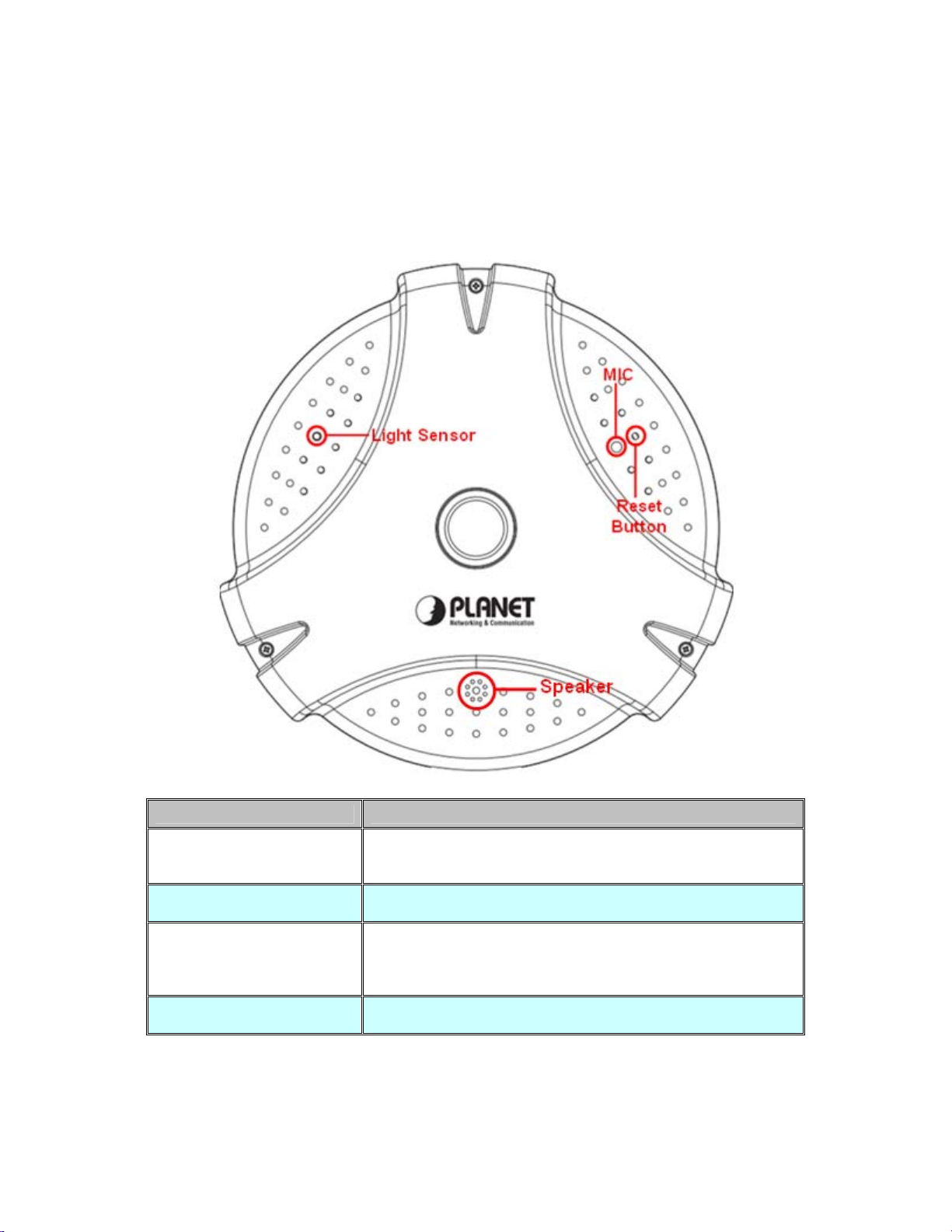
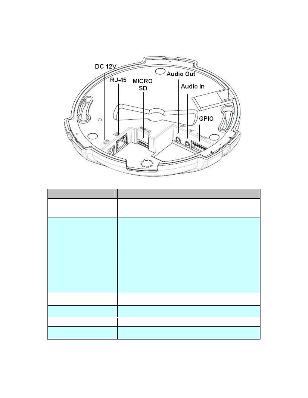
U2.2.1 Identification of ICA-HM830W physical detailU................................... 9
U2.3UUHardware InstallationU..................................................................................... 12
U2.3.1 Physical InstallationU............................................................................. 12
U2.3.2 Wall/Ceiling Mount Installation ProcedureU....................................... 13
U2.4UUInitial Utility InstallationU.................................................................................. 14
U2.5UUPreparationU...................................................................................................... 14
U2.5.1 Configure Network by PLANET IPInstallerU...................................... 14
U2.5.2 Open the Web-based UI of the select cameraU................................ 16
U2.6UUSetup ActiveX to use the Internet CameraU................................................. 17
U2.6.1 Internet Explorer 6 for Windows XPU.................................................. 17
U2.6.2 Internet Explorer 7 for Windows XPU.................................................. 18
U2.6.3 Internet Explorer 7 for Windows VistaU.............................................. 19
U2.7UUUsing UPnP of Windows XP or VistaU.......................................................... 20
U2.7.1 Windows XPU......................................................................................... 20
U2.7.2 Windows VistaU...................................................................................... 24
U3.UUWeb-based ManagementU..................................................................................... 25
U3.1 IntroductionU...................................................................................................... 25
U3.2 Connecting to Internet CameraU..................................................................... 25
U3.3 Live ViewU.......................................................................................................... 28
U3.4 Video ConfigurationU........................................................................................ 30
U3.4.1 Video General SettingsU....................................................................... 30
U3.4.2 Video Advanced SettingsU.................................................................... 32
U3.4.3 External Video SourceU........................................................................ 33
U3.5 Camera ConfigurationU.................................................................................... 34
U3.5.1 Camera General SettingsU................................................................... 34
U3.5.2 Camera Advanced SettingsU................................................................ 36
U3.6 Event ConfigurationU........................................................................................ 39
U3.6.1 Event ServerU......................................................................................... 39
U3.6.1.1 FTP serverU......................................................................................... 39
U3.6.1.2 Event Server RemoveU...................................................................... 40
U3.6.2 Motion DetectionU.................................................................................. 41
U3.6.3 I/O PortsU................................................................................................ 43
U3.6.4 Event ConfigurationU............................................................................. 44
U3.7 Schedule ConfigurationU.................................................................................. 46
U3.7.1 General SettingU.................................................................................... 46
U3.7.2 Storage SettingU..................................................................................... 47
U3.8 Network ConfigurationU.................................................................................... 48
U3.8.1 Network General SettingsU.................................................................. 48

U3.8.2 Network Advanced SettingsU............................................................... 49
U3.8.3 Network SMTP SettingsU...................................................................... 51
U3.8.4 DDNS serverU........................................................................................ 52
U3.8.5 WirelessU................................................................................................. 53
U3.9 System MaintainU.............................................................................................. 55
U3.9.1 System InformationU.............................................................................. 55
U3.9.2 User Account ConfigurationU............................................................... 56
U3.9.3 Date & Time ConfigurationU................................................................. 57
U3.9.4 Server MaintenanceU............................................................................ 58
U3.9.5 Log ServiceU........................................................................................... 60
U3.10 CustomizeU...................................................................................................... 60
U3.10.1 Use Default LookU............................................................................... 60
U3.10.2 Use Custom SettingsU........................................................................ 61
UAppendix A: Reset Factory Default SettingsU............................................................. 63
UAppendix B: PING IPAddressU..................................................................................... 64
UAppendix C: Bandwidth and Video Size EstimationU................................................. 65
UAppendix D: DDNS ApplicationU................................................................................... 66
UAppendix E: Configure Port Forwarding ManuallyU................................................... 71
UAppendix F: Troubleshooting & Frequently Asked QuestionsU................................ 74
UAppendix G: Product SpecificationU.............................................................................. 78

1. 0BIntroduction
PLANET ICA-HM830W is the new H.264 2Mega-Pixel Fixed Dome IP camera featuring a fish-eye lens for
360 degree panoramic wide angle view without blind spot. The ICA-HM830W delivers clear image through
Multi-streaming H.264 and Motion JPEG video up to UXGA (1600 x 1200 pixels). The fish-eye lens with
2Mega Pixel high resolution images provides 360 degree wide view surveillance and the panorama function
with quad view enables four different angles images to display simultaneously for monitoring and recording.
The ICA-HM830W digital Pan/Tilt and zoom function can provide users 9 different video modes including:
D360° Source image
D360°Table view
D180° double broad view
D180° double table broad view
D360° source view with 3 PTZ
DQuad view
D360° broad view with 2 PTZ
D180° source view with 3 PTZ
D180° broad view with 2 PTZ
Furthermore, the ICA-HM830W applies perspective correction software to eliminate the rounding normally
associated with fisheye lenses and thus save lots of traditional mechanical Pan/Tilt maintenance cost.
The ICA-HM830W is highly flexible to be applied in various kinds of IP surveillance environment. It has
built-in ICR (IR-cut filter Removable) for day / night surveillance and is compatible with IEEE 802.11b/g/n
wireless technology and WEP / WPA encryptions. In addition, the ICA-HM830W provides surveillance
functions including DI/DO alarm, Micro SD card support for local storage, and 2-Way audio that enables
audio communication between local and remote ICA-HM830W installed sites by connecting the external
microphone and speaker.
The ICA-HM830W is the perfect panoramic surveillance application for the hallway, stores or offices so
customers do not need to install multiple IP cameras and thus can save lots of installation and maintenance
cost. Moreover, the ICA-HM830W can be managed by PLANET Cam Viewer 3 IP-Surveillance
management software for multi-camera video surveillance application and provides monitoring, recording and
event management functions to secure your property and life.
1.110BOverview
This user’s guide explains how to operate this camera from a computer. User should read this
manual completely and carefully before you operate the internet camera.
11B1.2 Features
•360 degree Fish-Eye panoramic wide angle view
•9 different 360 degree/ 180 degree video mode including digital PTZ function
•High quality 2Mega-Pixel CMOS image sensor (maximum up to 1600 x 1200 resolution)
•H.264 and M-JPEG dual codec
•Day/Night switch with ICR (IR-cut Filter Removable)
•IEEE 802.11b/g/n wireless LAN with WEP and WPA encryption
•2-Way audio with built-in microphone and speaker
•10 motion detection areas / E-mail and FTP alert
•External I/O trigger for various surveillance application
•High performance video decoder to decrease image distortion
•DDNS and FTP uploading provide more alternatives in surveillance network

1.312BPackage Contents
IP Camera unit x 1
Power Adapter x 1
Quick Installation Guide x 1
User’s Manual CD x 1
Wall Mount Kit x 1
GPIO Connector x 1
NOTE: 1. If any of the above items are missing, please contact your dealer immediately.
2. Using the power supply that is not the one included in Internet camera packet will
cause damage and void the warranty for this product.

2. 1BBasic Setup
This chapter provides details of installing and configuring the Internet camera
2.1 13BSystem Requirement
The Internet Camera can be monitoring on all of Windows operating system that suggest with
system requirment below in order to got better video performance when resolution up to 2
megapixel.
CPU Intel® Core2 Duo E3500 2.7GHz
RAM 2 GB
Video RAM 128MB
Display Chip nVIDIA GeForce 8500GT or ATI Radeon HD 4350 or above
Display Resolution 1024 x 768 24bits
Operating System Windows 2000 SP4 / Windows XP Pro SP2 / Windows 2003 / Vista/
Windows 7
DirectX 9.0c or above
Network Wired Ethernet 100Base-TX
NOTE:
1. The listed information is minimum system requirements only. Actual requirement
will vary depending on the nature of your environment.
2. The ICA-HM830W can be managed by PLANET Cam Viewer Three if you want
to configure more detail information and settings of camera viewer plus software
please refer to the CD-ROM folder “D:\Manual\Cam Viewer 3\”, assume D is
your CD-ROM drive.

2.2 14BPhysical Description
30B2.2.1 Identification of ICA-HM830W physical detail
Font view
Interface Description
Light Sensor The Light sensor is for detect IP Camera environment
illuminant, and if IP Camera in the dark/night environment that
will let IR cut filter off for clearly night view.
MIC The IP Camera has built-in an internal microphone. This
microphone is hidden in the pinhole located on the front panel.
Reset Button
This button is hidden in the pinhole. This button is used to
restore the all factory default settings. Sometimes restarting
the Internet Camera will make the system back to a normal
state.
Speaker The IP Camera has built-in an internal speaker. This speaker
is hidden in the pinhole located on the front panel.

Rear View
Interface Description
Power Jack The input power is DC 12V, 2A.
Note:ONLY use package power adapter supplied with the
internet. Otherwise, the product may be damaged.
RJ-45 LAN socket
Connect to PC or Hub/Switch.
For connect to 10Base-T Ethernet or 100Base-TX Fast
Ethernet cabling. This Ethernet port built auto-negotiation
protocol can detect or negotiate the transmission speed of the
network automatically. Please use CAT-5 cable to connect the
Network Camera to a 100Mbps Fast Ethernet network switch
or hub.
Power / Status LED (orange color)
This LED will be flashing while camera DC power is on
camera starting, and this LED light while camera ready.
Network LED (green color)
This LED will be flashing while the camera accessing of the
camera.
MicroSD Card Slot The IP Camera has built-in a Micro SD card slot accepts Micro
SD memory card for image / video event recording.
Audio Out Connect a loud speaker to the IP Camera. This is for voice
alerting and two-way audio.
Audio In Connect a microphone to the IP Camera.
GPIO The 7 pin terminal block includes 4 input ports and 1 output
ports.

Terminal block for I/O connectors:
Name Pin Function
GND 1
Digital input 4 2
Digital input 3 3
Digital input 2 4
Digital input 1 5
Four sets of Digital Input, DI1 until DI4; the internal device
is also photo-coupled electrical relay. In practice, the
external device can be simply an On/Off switch. Four sets
of On/Off switch can be connected as different trigger
source.
DO_NO 6
DO_COM 7
Digital output implementation; Pin6 to COM (Pin7) is a
Photo-coupled relay on Normal Open status. External
device can directly connect to the terminals. However the
current that will go through the 2 nodes must not exceed
130mA. An external “Relay” can also be connected to the
terminals as an implementation. In this case, current
(or/and voltage) limitation is specified by the external
Relay.

2.3 15BHardware Installation
31B2.3.1 Physical Installation
Step 1. Prepare a PC with Ethernet link to the network
Step 2. Connect an Ethernet cable
Connect LAN port (RJ-45) of the IP Camera to a network switch. Attach the power
supply
Plug in power adapter to IP Camera and connect another end to power outlet.
NOTE: Only use the power adapter supplied with IP Camera otherwise, the product may
be damaged.
Step 3. Plug Power on 110v or 220V
Ensure the power adaptor specification matches the power system (110V AC or
220V AC) and connect the adaptor to the outlet
Step 4. Check LED status
The Power LED is defined to identify IP Camera status. When IP Camera booting
the LED will be flashing and while IP Camera is ready the LED will be green.

32B2.3.2 Wall/Ceiling Mount Installation Procedure
Step1. Take the wall mount bracket, put it on the target place and fix it with the supplied
screws (total of 2).
Step2. Load the camera into the wall mount, be sure the cameras are mated with two fixed
screw, and rotate the camera to lock it in position.

2.4 16BInitial Utility Installation
This chapter shows how to quick set up your IP Camera. The IP Camera is with the default
settings. However to help you find the networked IP Camera quickly the Windows utility (PLANET
IPInstaller) can search the IP Cameras in the network that shall help you to configure some basic
setting before you start advanced management and monitoring.
Please insert the bundle CD disk into your CD/DVD-ROM drive. When the welcome web page
appears, please click your IP Camera name on the IP Camera list i.e. ICA-HM830W. Then click on
the utility IPInstaller to start the program.
2.5 17BPreparation
When you installed the camera on a LAN environment, you may execute PLANET IPInstaller to
discover camera’s IP address and set up related parameters in the camera.
33B2.5.1 Configure Network by PLANET IPInstaller
Please click “Device Search” button. PLANET IPInstaller will list all networked IP Camera in the
LAN. If the IP Camera doesn’t be found, you may check whether this IP Camera is connect to
network properly and press the search button again.
1. Click the menu bar Tool > Device Search to search the device in the LAN.
2. Select IP Camera with the MACAddress corresponds to the IP Camera that is to be
configured.

3. Double click the item to open the Property Page or click the menu bar > Single Device
Seeting
4. After filling the desired settings in the properties, click on “Set” button to complete the
configuration settings.

34B2.5.2 Open the Web-based UI of the select camerab-based UI of the select camera
If IPInstaller finds IP Camera, please select the device you want to view and click the “Open
Web” button. Then you could see the video from IP Camera directly.
If IPInstaller finds IP Camera, please select the device you want to view and click the “Open
Web” button. Then you could see the video from IP Camera directly.
1. To access the Web-based UI of the selected unit, run the menu bar > Open web on the
menu bar.
1. To access the Web-based UI of the selected unit, run the menu bar > Open web on the
menu bar.
If the Internet Camera has been configured correctly, the default Web browser will open to the
home page of the selected device.
If you find your browser is opened and automatically connected to the camera Home Page, it
means you’ve assigned an IPAddress to the unit successfully. Now you can close the IP Installer
and start to use your camera.

2.6 18BSetup ActiveX to use the Internet Camera
The Internet Camera web pages communicate with the Internet Camera using an ActiveX control.
The ActiveX control must be downloaded from the Internet Camera and installed on your PC. Your
Internet Explorer security settings must allow for the web page to work correctly. To use the
Internet Camera, user must setup his IE browser as follows:
35B2.6.1 Internet Explorer 6 for Windows XP
From your IE browse ΔTools” ΔInternet Options…” ΔSecurity” ΔCustom Level…”, please
setup your “Settings” as follow.
Set the first 3 items
• Download the signed ActiveX controls
• Download the unsigned ActiveX controls
• Initialize and script the ActiveX controls not masked as safe to Prompt
By now, you have finished your entire PC configuration for Internet Camera.

36B2.6.2 Internet Explorer 7 for Windows XP
From your IE browse ΔTools” ΔInternet Options…” ΔSecurity” ΔCustom Level…”, please
setup your “Settings” as follow.
Set the first 3 items
• Allow previously unused ActiveX control to run…
• Allows Script lets
• Automatic prompting for ActiveX controls
By now, you have finished your entire PC configuration for Internet Camera.

37B2.6.3 Internet Explorer 7 for Windows Vistasta
From your IE browse ΔTools” ΔInternet Options…” ΔSecurity” ΔInternet” ΔCustom
Level…”, please setup your “Settings” as follow.
From your IE browse ΔTools” ΔInternet Options…” ΔSecurity” ΔInternet” ΔCustom
Level…”, please setup your “Settings” as follow.
• Enable “Automatic prompting for ActiveX controls”• Enable “Automatic prompting for ActiveX controls”
• Prompt “Initialize and script active controls not marked….”• Prompt “Initialize and script active controls not marked….”
From your IE browse ΔTools” ΔInternet Options…” ΔSecurity” ΔTrusted Sites”
ΔCustom Level…”, please setup your “Settings” as follow.
• Enable “Automatic prompting for ActiveX controls”
• Prompt “Initialize and script active controls not marked….”
By now, you have finished your entire PC configuration for Internet Camera.

2.7 19BUsing UPnP of Windows XP or VistaUPnP of Windows XP or Vista
38B2.7.1 Windows XP38B2.7.1 Windows XP
UPnP™ is short for Universal Plug and Play, which is a networking architecture that provides
compatibility among networking equipment, software, and peripherals. This device is an UPnP
enabled device. If the operating system, Windows XP, of your PC is UPnP enabled, the Internet
Camera will be very easy to configure. Use the following steps to enable UPnP settings only if your
operating system of PC is running Windows XP.
NOTE: Windows 2000 does not support UPnP feature.
Go to Start > Settings, and Click Control Panel
The “Control Panel” will display on the screen and double click “Add or Remove Programs”to
continue
The “Add or Remove Programs” will display on the screen and click Add/Remove Widows
Components to continue.
Other manuals for ICA-HM830W
1
Table of contents
Other Planet IP Camera manuals

Planet
Planet ICA-HM131 User manual

Planet
Planet ICA-600 User manual

Planet
Planet ICA-HM830 User manual

Planet
Planet CIA-3250V User manual

Planet
Planet ICA-700 User manual

Planet
Planet ICA-HM126 User manual

Planet
Planet ICA-300 User manual

Planet
Planet ICA-3350P User manual

Planet
Planet ICA-310 User manual

Planet
Planet ICA-108 User manual

Planet
Planet ICA-W7100 User manual

Planet
Planet ICA-501 User manual

Planet
Planet ICA-HM312 User manual

Planet
Planet ICA-525 User manual

Planet
Planet ICA-HM100 User manual

Planet
Planet ICA-HM131 User manual

Planet
Planet ICA-3350V User manual

Planet
Planet ICA-HM830W User manual

Planet
Planet ICA-H610 User manual

Planet
Planet ICA-HM130 User manual