manuals.online logo
Brands
  1. Home
  2. •
  3. Brands
  4. •
  5. Pollard
  6. •
  7. Tools Storage
  8. •
  9. Pollard 163-530-34 User manual

Pollard 163-530-34 User manual

This manual suits for next models

1

Other Pollard Tools Storage manuals

Pollard 120D User manual

Pollard

Pollard 120D User manual

Pollard 152 User manual

Pollard

Pollard 152 User manual

Pollard 120 User manual

Pollard

Pollard 120 User manual

Pollard 131 User manual

Pollard

Pollard 131 User manual

Popular Tools Storage manuals by other brands

Vestil WT-2424 owner's manual

Vestil

Vestil WT-2424 owner's manual

Kendall Howard ESDW-9630-1000 owner's manual

Kendall Howard

Kendall Howard ESDW-9630-1000 owner's manual

Ryobi RWB03 Original instructions

Ryobi

Ryobi RWB03 Original instructions

Husky H27CH5TR4BGK Use and care guide

Husky

Husky H27CH5TR4BGK Use and care guide

Scheppach ts 2100 Translation from original manual

Scheppach

Scheppach ts 2100 Translation from original manual

DIVERSIFIED WOODCRAFTS SHAIN GSB-6024 Assembly instruction

DIVERSIFIED WOODCRAFTS

DIVERSIFIED WOODCRAFTS SHAIN GSB-6024 Assembly instruction

Cassese CS200 CART user & parts manual

Cassese

Cassese CS200 CART user & parts manual

Cornwell Tools CTB360AKBK Assembly instructions

Cornwell Tools

Cornwell Tools CTB360AKBK Assembly instructions

Workzone 99609 Assembly instructions

Workzone

Workzone 99609 Assembly instructions

Stanley STST83800-1 instruction manual

Stanley

Stanley STST83800-1 instruction manual

Perel ROLLER SHUTTER STORAGE CABINET Assembly instructions

Perel

Perel ROLLER SHUTTER STORAGE CABINET Assembly instructions

BGS technic 4107 manual

BGS technic

BGS technic 4107 manual

Tennsco RXHS-962484 Assembly Instructions/Parts Manual

Tennsco

Tennsco RXHS-962484 Assembly Instructions/Parts Manual

Grizzly T1240 owner's manual

Grizzly

Grizzly T1240 owner's manual

Rubi 66924 manual

Rubi

Rubi 66924 manual

Draper 77020 instructions

Draper

Draper 77020 instructions

Batavia CROC LOCK COMPACT Translation of the original instructions

Batavia

Batavia CROC LOCK COMPACT Translation of the original instructions

Pinnacle GOS196 quick start guide

Pinnacle

Pinnacle GOS196 quick start guide

manuals.online logo
manuals.online logoBrands
  • About & Mission
  • Contact us
  • Privacy Policy
  • Terms and Conditions

Copyright 2025 Manuals.Online. All Rights Reserved.

E
S
T
.
1
9
2
1
163-530-34 & 163-530-35
Cabinet Work Bench
Assembly Instructions
www.pollardbros.com
3/8” x 3/4” Hex Head
Machine Screw
3/8” Lock Washer
3/8” Hex Nut
(2) Cabinet Sides (Left & Right) (1) Back Plate (1) Kick Plate Channel (2) Shelves (1) Door Jam (2) Cabinet Doors (Left & Right)
(1) Door Center Post (1) Maple Top (3) Drawer Handles (3) Drawer Covers (3) Drawers
Includes:
xx
x
12 12
18
1/4” x 1 1/4” Flat Head
Machine Screw
1/4” x 5/8” Round Head
Machine Screw
1/4” Hex Nut 1/4” Lock Washer
3/8” x 2 1/2” Flat Head Machine Screw
#12- 3/4”Wood Screw
8/32” x 3/8” Flat Head
Machine Screw
8/32” Hex Nut
Spacer
x
6x
6x
22
x
5
x
6
x
27
x
27
x
30
x
5
Note: For 163-530-35 (6) 3/8” x 3 1/2” Flat Head Machine
Screws will replace (6) 3/8” x 2 1/2” Flat Head Machine Screws.
Tools Needed:
wrench at head screwdriver phillips head screwdriver power drill
Cylinder Lock Attachment
x
3
T-Handle Lock Cylinder Lock
x
3
x
2
2” x 2” Butt Hinges
x
4
x
3
Drawer Handle
[2]
1Insert Cabinet Back Plate in inside of rear ange
of Left Cabinet Side. Attach Left Cabinet Side to
Cabinet Back Plate using (3) 1/4” x 5/8” Round
Head Machine Screws, 1/4”Hex Nuts, and 1/4”
Lock Washers. Attach Right Cabinet Side the
same way. Note: Cabinet Back Plate is packaged
under a sheet of cardboard, banded to the crated
Maple Top.
Tip Cabinet Sides and Back Plate on the back and
attach one of the Cabinet Shelves to bottom
cross of each side with turned down ange with
5/16” hole to the front. Fasten with (4) 3/8” x 3/4”
Hex Head Machine Screws, 3/8”Hex Nuts, and
3/8” Lock Washers. Leave out Front Screws,
Washers, and Nuts for Step 3.
2Leave out Screws until Step 3.
3Assemble Kick Plate with anges to the back,
using (2) 3/8” x 3/4” Hex Head Machine Screws,
3/8” Hex Nuts, and 3/8”Lock Washers.
4Insert second Shelf with turned down edge
front and attach using (6) 3/8”x 3/4” Hex Head
Machine Screws, 3/8”Hex Nuts, and 3/8” Lock
Washers.
5Attach Door Jam to Uprights using (2) 1/4”x 1
1/4” Flat Machine Screws, 1/4”Hex Nuts, and
1/4” Lock Washers and (2) Nylon Spacers. Note:
Spacers should be between Uprights and Door
Jam.
Steps:
[3]
Attach Door Center Post to Door Jam and
Shelves using (3) 1/4”x 1 1/4”Flat Head
Machine Screws, Hex Nuts, and Lock Washers,
and (3) Nylon Spacers. Note: Spacers should be
between Center Post and Shelves and Door Jam.
6
7
8Pull partially assembled Bench to upright
position. Square and level then tighten all
screws.
9
Cabinet Door
Attach T-Handle Locks to Cabinet Doors.
Remove End Screw w/ Sem from Barrel, then
remove Cam and 3/4”Hex Nut. Insert
T-Handle into lock hole and reassemble Hex
Nut, Cam, Sem, and End Screw according to
diagram.
10 Remove drawer from the drawer cover. Note:
To detach the drawer depress black lever up on
right and down on left slides simultaneously as
you pull the drawer out.
Attach 2”x 2”Butt Hinges to Cabinet Doors
and attach to sides using (16) 1/4”x 5/8”
Round Head Machine Screws, 1/4”Hex Nuts,
and 1/4” Lock Washers.
Pollard Brothers Manufacturing 5504 N. Northwest Highway Chicago IL 60630
. . . .
phone(773)763-6868 fax(773)763-4466 toll free(800) 551-5566
[4]
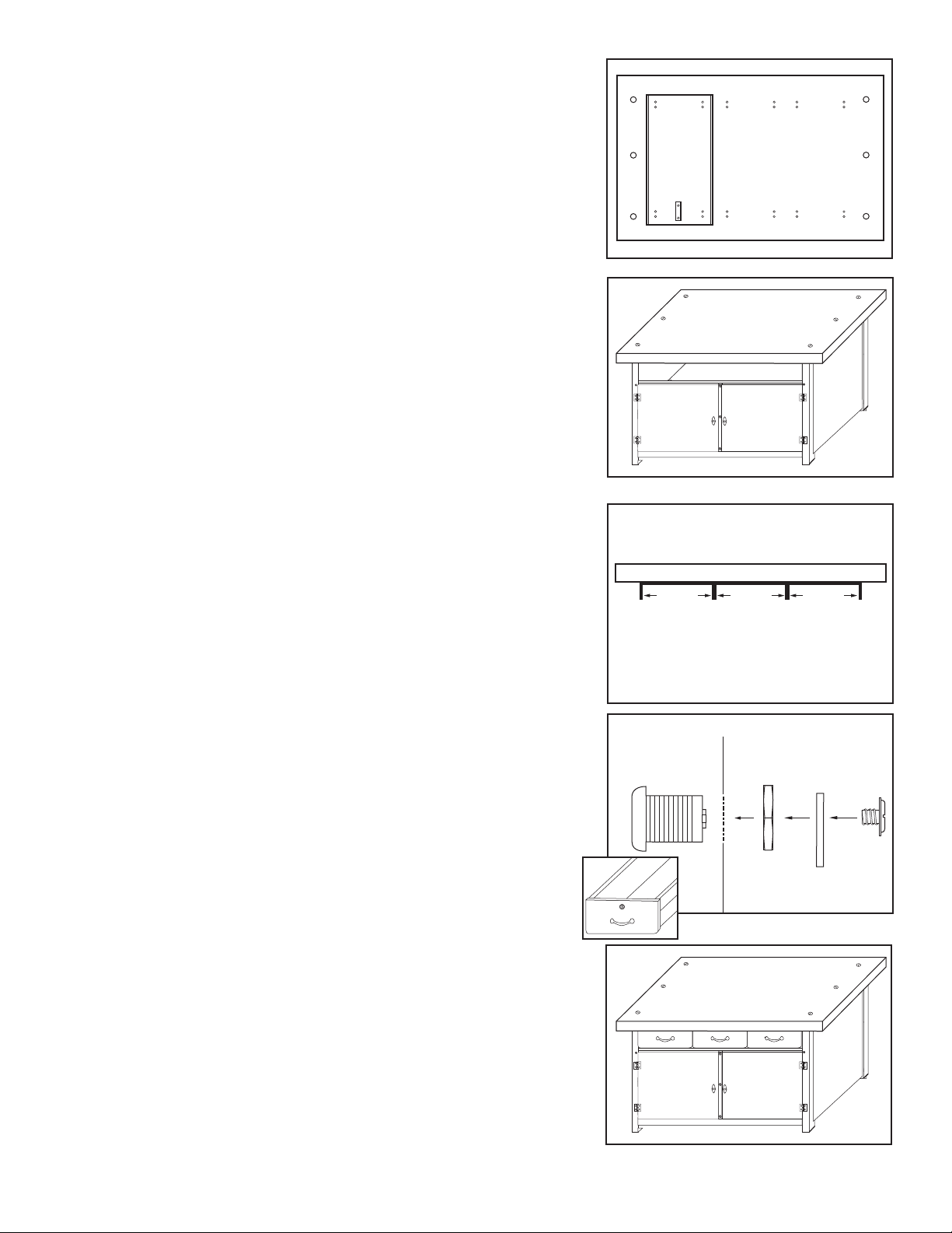
Attach Drawer covers and Cylinder Lock
Attachment to Maple Top underside using
Pilot Holes and (30) #12 3/4”Wood Screws.
Verify interior spacing of 15⁄”between
sides of drawer cover.
11
Turn Maple Top over and attach to Cabinet
Side using (6) 3/8” x 2 1/2” Flat Head
Machine Screws and 3/8” Hex Nuts. Note: 2
5/8” thick Maple Top will use (6) 3/8” x 3 1/2”
Flat Head Machine Screws.
After placing Maple Top on cabinet and
attaching, make sure interior spacing of
Drawer cover remains 15⁄”. Note: If interior
drawer spacing is o, gently bend sides of
drawer cover to correct measurment.
15⁄” 15⁄” 15⁄”
12
13
Drawer Front
Attach Cylinder Locks to Drawer Fronts.
Remove End Screw, Cam, and 1/2” Hex Nut
from Cylinder. Insert Cylinder into lock hole
and replace 1/2”Hex Nut, Cam, and End
Screw according to diagram. Then attach
Drawer Handles to Drawer fronts using (6)
8/32” x 3/8” Flat Head Machine Screws.
Carefully insert Drawer slide on drawer into
the drawer slide on the drawer cover making
sure slides are lined up and square. Note: After
inserting drawer, fully close drawer to ensure
drawer has locked. Drawer must be inserted
slowly and squarely to ensure proper attach-
ment to drawer slide on underside of cover.
14
15
Note: 5’ Model has 3” overhang on each side of bench.