Porsche PCCM Plus Manual

TechnicalInformation 911(996)
56/20 ENU 9112 9
Porsche Classic Communication Management Plus (PCCM Plus)
VehicleType: 911 (996) and Boxster (986)
ModelYear: As of1997
Restriction: 1997 – 2005
Important: For converting DIN1 radio (step 2) to PCCM Plus (DIN2), the parts listed in the conversion parts list
DIN1 to DIN2 mustalsobe ordered.
Additionalinstallationvideos areavailable forinstallation,link:
https://ppn.porsche.com/portal/docs/DOC-111500
Notes: ComparedwithPorsche CommunicationManagement(PCM)generation 1and2.0, Porsche Classic
CommunicationManagement Plus(PCCM Plus) includesthe following:
• AppleCarPlay®
• GOOGLE®AndroidAuto
• Digitaltouchscreendisplay(7-inch)
• ExternalmediaboxforUSB/AUX/USBforAppleCarPlay/GOOGLE®AndroidAuto
• 2 x microSDHC card slots
• Bluetooth®hands-freesystem
• SiriusXM-Ready®(USAonly)
Figure1
AfterSales Aug31, 2020
Page 1 of 12

911(996)
99112 ENU 56/20 TechnicalInformation
Parts Info: 996.642.591.00 NAVIGATION SYSTEM, USA(PCCMPlus)
Conversion
parts listDIN1
toDIN2:
Onlyfor vehicles withDIN1radio
Important: Beforebeginningtheconversion fromDIN1toPCCM Plus(DIN2),theparts listedin the
conversion parts listDIN1toDIN2 must alsobeordered.
Thisconversionis explained instep2.
OverviewofconversionDIN1to DIN2
911 Turbo (996), 911 GT3 from model year 2003, 911 (996) 2002–2005, Boxster (986)
2003–2004
996.552.653.04 1x Retainingbar
Overviewofconversion DIN1toDIN2
996.552.231.12.01C* 1x Frontsupport frame,black
Overviewofconversion DIN1toDIN2
996.552.339.00.01C* 1x Frameforair-conditioningcontrolpanel,black
Overviewof
conversionDIN1 to DIN2-D-
999.919.182.09 2x Oval-headscrew
OverviewofconversionDIN1to DIN2-E-
Aug31, 2020
Page 2 of 12 AfterSales

TechnicalInformation 911(996)
56/20 ENU 9112 9
996.552.131.05.A03* 1x Frontsupport frame,black
Overviewofconversion DIN1toDIN2
-C -
996.552.339.00.01C* 1x Frameforair-conditioningcontrolpanel,black
Overviewof
conversionDIN1 to DIN2-D-
999.919.182.09 2x Oval-headscrew
OverviewofconversionDIN1to DIN2-E-
Boxster (986) 1997–2002
986.552.131.09.A03* 1x Frontsupport frame,black
Overviewofconversion DIN1toDIN2
-C -
996.552.339.00.01C* 1x Frameforair-conditioningcontrolpanel,black
Overviewof
conversionDIN1 to DIN2-D-
999.919.182.09 2x Oval-headscrew
OverviewofconversionDIN1to DIN2-E-
* Colors and materials that were originally used are subject to availability. Communicate color
deviations to the customer during the sales process.
Note: If the media box is not installed in the glove box, storage compartment 996.552.253.01C
must be ordered.
PCCMparts
list:
Figure2
996.642.591.00 1x PorscheClassic Communication ManagementPlus,USA
Figure
2-1-
996.642.595.00 1x Mountingparts
Figure2-2-
911.645.507.00 1x Microphone
Figure2-3-
911.645.505.00 1x GPSantenna
Figure2-4-
911.645.513.00 1x Multimediainterface
Figure2-5-
AfterSales Aug31, 2020
Page 3 of 12
911 (996) 1998–2001

911(996)
99112 ENU 56/20 TechnicalInformation
996.642.580.00 1x MOSTcontrolunitwith connecting line
Figure2-6- and
Figure
2-7-
911.642.313.00 1x SiriusXM® connecting line,USA ONLY
Figure2-11-
911.645.574.55 1x AntennaadapterplugUSA ONLY
Figure2-12-
996.642.585.00 1x MOSTbridge
Figure2-15-
Important: The relevantmap material isprovided via a separateSD card:
996.642.502.00 1x SDmemorycardfornavigation system withnavigationdata for
USA,Canada
Forvehicleson whichPCMgeneration 1(M662)is installed,thefollowingpartsarealso required:
996.612.009.01 1x GPSantennaconnectinglineM662
996.642.587.00 1x Groundlinefor amplifierM662+M680
On986vehicles withanew 987.647.105.00antennaamplifier, the antennaline986.642.573.00 must
alsobe ordered.
Installing: Important: BeforeinstallingPCCMPlus, pleasecheckthatthe soundsystemis functioning correctly
usingthe system tester. Ifthereisafault,thismust becorrectedbeforehand.
1 Preliminarywork
1.1 Remove batterycover and disconnectandcover thebattery.
1.2 Removeradio,heating/air-conditioningcontrolpanel,trim forswitches,center airvents and
frontretainingbracketfor radio.
1.3 Removelefttrimpanelfor centerconsole, centerconsole trim,CDcompartmentand
storagecompartment.
1.4 Pullstandardradiooutofitsslide-inmoduleanddisconnect electric plugconnection.
Aug31, 2020
Page 4 of 12 AfterSales

TechnicalInformation 911(996)
56/20 ENU 9112 9
2.1
2.1 Routewireharness forheating/air-condi-
tioningcontrolpanel
2.1fromthe instal-
lationopening
2.1inthedashboardto
theinstallationslot
2.1-C -inthecenter
consoleandsecureit.
2.2 Pullinsertsleevesoffoldtrim for heating/air-
conditioningcontrolpaneland insertthem
intothe heating/air-conditioningcontrolpanel
2.2.
2.3 Insert connectorinto heating/air-conditioning
controlpanel.
2.2
2.4 Insertheating/air-conditioningcontrolpanel
2.2intothelowerinstallationslotof the
centerconsoleand securewithscrews
2.2
-C - .
NOTE:Use new screws(Torx 4x20, see
parts list).
2.5 Insert rearretainingbar
2.2forPCM2 and
securewithscrews
3 Remove A-pillaratthe right.
Figure7
3.1 OnallvehicleswithoutM440, routeadapter
cable from antenna
Figure 7 -2- to PCCM
Plus radio slot.
Disconnect windscreen antenna from the
antenna amplifier
Figure 7 -2-. Connect
Figure 7 -5- windscreen antenna to adapter
cable
Figure 2 -10-.
Loosen screw
Figure 7 -3- and install
ground line
Figure 7 -4-. Tighten the screw
again.
AfterSales Aug31, 2020
Page 5 of 12
2 Conversionof air-conditioningcontrolpanel

911(996)
99112 ENU 56/20 TechnicalInformation
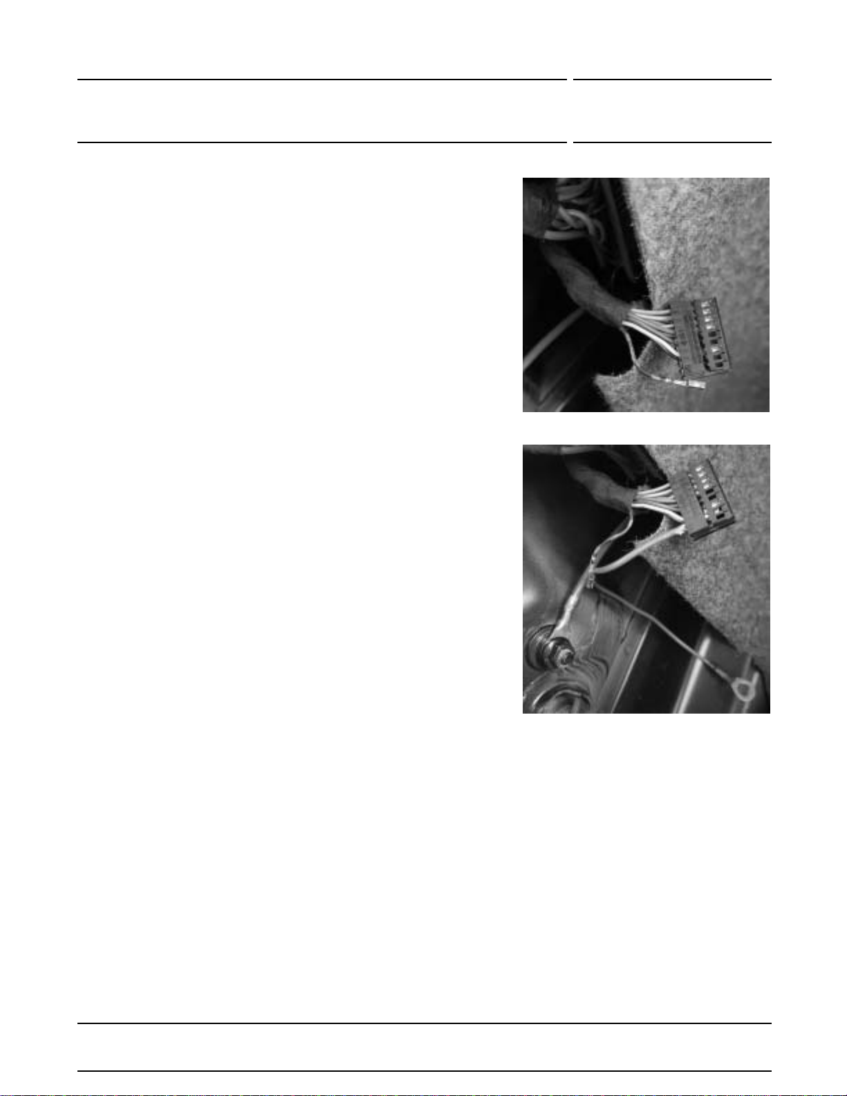
cable986.642.573.00 (not
includedinscope ofdelivery)must beused.
Figure8
4 Installingadd-on partsforUSA
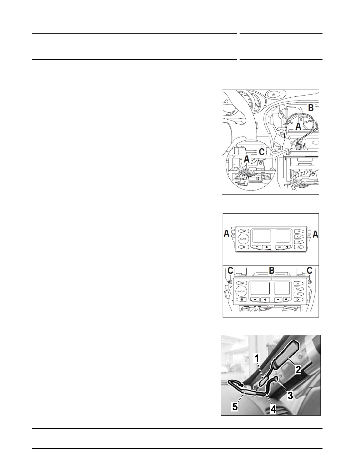
Installmicrophone
-2- forhands-freeequipment
on the steering columncasing. Route the
microphonecabletothePCCM Plus. The microphone
installedin thevehiclecannotbe used(M618,666).
Figure9
4.1 Onvehiclesthatdonothave aGPSantenna
installedasstandard,installGPS antenna
Figure2-4- in the dashboardareaandroute
thecable to the PCCM Plus.
For M662 up to 2002 (PCM1),pleasealso
usethe following: 996.612.009.01 (not
includedinscope of delivery). Connect the
GPSantenna(onthenavigation computer)
installedatthe factorytothePCCM Plususing
theadaptercable. Alternatively,thesupplied
GPSantennacan be used.
Figure10
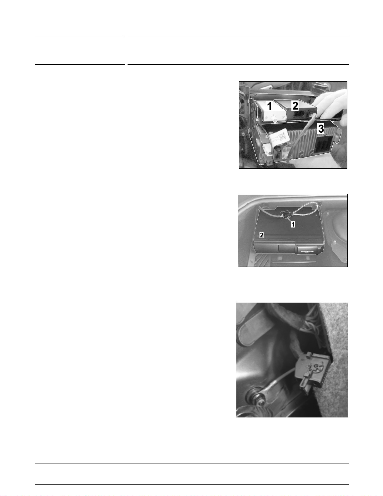
4.1.1 Installthe supplied media interface
Figure2-5- in the center
consolestorage compartment
Figure9-1-.Alternatively,the
mediaboxcan alsobeinstalled in
theglovebox
Figure10-1-
Note: Thecableforthemediabox
mustbe no longerthan50 cm in
ordertoensuredataquality. During
installation,the media boxmust
onlybe securedin the installation
positionafter installingthe PCCM
Plus.
Aug31, 2020
Page 6 of 12 AfterSales
3.1.1 On 986 vehicles with antenna
amplifier987.647.105.00, adapter

TechnicalInformation 911(996)
56/20 ENU 9112 9
Figure11
5.1 OnvehicleswithM662up to modelyear
2002,the alarmcontact
Figure11-1- on
theretainingframe mustbeinsulated.
Figure12
5.2 Securethesidepanelat theleftand right
Figure12-3- to the transverse strut
Figure
2-2-using twoscrewson each side
Figure
12-1-.Install
Figure2-2-.
Figure13
5.3 Insert device
Figure13-2- intoZretaining
bracket
Figure13-1- and install the side
panelswith transverse strutonthe device
from therear. Check that thedeviceis
installedsecurely. Screwthedevice totheZ
retaining bracketwithfour screws.
AfterSales Aug31, 2020
Page 7 of 12
5 Installingdevice

911(996)
99112 ENU 56/20 TechnicalInformation
Figure14
5.4 Installationof MOSTcontrolunit
Figure
2-6,7-USA: . AffixMOST controlunit
Figure14-2- on the transverse strutof the
Zretainingframe
Figure14-3- usingthe
supplieddouble-sidedadhesive strip and
connectthe plug connectiontothe device.
5.5 AffixDABbox
Figure2-8-RDW only:
Figure14-1-on the transversestrutof the
Zretainingframe
Figure14-3- usingthe
supplieddouble-sidedadhesive strip and
connectthe plug connectiontothe device.
RoutinglinesforDAB receiver
Figure2-9-
underthetransverse strut
Figure15
For M665 with M622 from 2003:
Figure
2-12- mustalsobe used.
5.5.1 Installthe suppliedMOSTbridge
Figure15-1- 996.642.585.00 on
theCDchanger
Figure15-2-.
5.5.2 Installinggroundline: Onvehicles
(1997–2001)withM662(PCM
generation1) and M680(Digital
soundpackage), anadditional
groundline996.642.587.00 must
beroutedto the amplifier.
Ground line not included in scope of delivery.
Figure15.2
Disconnectblack18-pin connector
housingfromthe amplifier
Figure
15.2.
Aug31, 2020
Page 8 of 12 AfterSales

TechnicalInformation 911(996)
56/20 ENU 9112 9
Figure15.3
Removefuseon connectorhousing
and disconnect andinsulate
(DSPdata)line, contactno. 17
black/red/yellow.
Figure15.3
Figure15.4
Connectadditionalgroundline
996.642.587.00at contactno.
17. Re-installconnector housing
Figure15.4
AfterSales Aug31, 2020
Page 9 of 12

911(996)
99112 ENU 56/20 TechnicalInformation
Figure15.5
Securegroundlineattheground
points. Re-installblackconnector
ontheamplifier.
Figure15.5
5.6 Slidedevicewith retainingframe intothe
installationslot andcompletethe vehicle.
5.7 Readoutthefault memory and clear itif
necessary. Faultsthatarepresentfollowing
installationandarenot deleted canbe
ignored.
Important note: Thedevice cannot be
diagnosedfortechnical reasons. Asaresult,
thefollowing faults will be enteredinthe fault
memory.
• 9114PCM controlunit
• 9151Unknown error
Thefaults donot affect other functions inthe vehicle and can be ignored.
6Note: Onvehicles(1997–2002) withM662(PCM1),the amplifieroutput mustbeactivated inthe
PorscheClassicCommunicationManagementPlus (PCCM Plus). Unlessthis isactivated, nosound
willbe heardfromtheloudspeakerswhen the device isswitchedon.
No12-voltoutput voltage isemittedon the miniISOconnector(yellow)pin 6. Toactivatethis, please
proceedasfollows:
6.1 SelecttheSettings buttoninthe HOME screen.
Figure 16
Aug31, 2020
Page 10 of 12 AfterSales

TechnicalInformation 911(996)
56/20 ENU 9112 9
Figure17
6.3 Pressthe CAN Switch buttononcetochange fromCAN to AMP.
Figure18
AfterSales Aug31, 2020
Page 11 of 12
6.2 Select the Volume menu item and touch and hold it for approx. 10 seconds.

911(996)
99112 ENU 56/20 TechnicalInformation
Figure19
6.4 Restart thedevice.
91102340: InstallingPorsche ClassicCommunicationManagement Plus Labortime: 320 TU
Aug31, 2020
Page 12 of 12 AfterSales
Important Notice: Technical Bulletins issuedbyPorscheCarsNorth America, Inc. areintendedonlyforusebyprofessional automotivetechnicianswhohaveattendedPorscheservicetraining
courses. They arewrittentoinformthosetechniciansofconditions thatmayoccuronsomePorschevehicles,ortoprovideinformationthatcouldassistintheproperservicingofa vehicle. Porsche special
tools may be necessary in order to perform certain operations identified in these bulletins. Use of tools and procedures other than those Porsche recommends in these bulletins may be detrimental to the
safe operation of your vehicle, and may endanger the people working on it. Properly trained Porsche technicians have the equipment, tools, safety instructions, and know-how to do the job properly and
safely. Partnumberslistedinthesebulletinsareforreference only. Theworkprocedures updated electronically inthePorschePIWISdiagnosticandtestingdevicetakeprecedenceand,intheeventofa
discrepancy, theworkproceduresinthe PIWISTesterarethe ones thatmustbefollowed. © 2020 Porsche Cars North America, Inc.
Table of contents
Other Porsche Car Video System manuals

Porsche
Porsche Connect Release note

Porsche
Porsche PCM User manual

Porsche
Porsche 997.642.591.00 User manual

Porsche
Porsche BT45-CDR30 User manual

Porsche
Porsche Classic Communication Management Plus Parts list manual

Porsche
Porsche Connect Release note

Porsche
Porsche Classic Communication Management Plus User manual

Porsche
Porsche Porsche Rear Seat Entertainment User manual

Porsche
Porsche Connect Release note

Porsche
Porsche PCM3.1 User manual