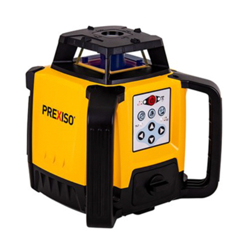
Prexiso PR500HVG User manual

IMPORTANT:
Read before Using EN
PR500HVG
SELF-LEVELING ROTARY LASER
www.prexiso-eu.com
WARRANTY
LIMITED
YEARS
2
1
PR500HVG

IMPORTANT SAFETY INSTRUCTIONS
Do not use the product before you have studied the Safety instructions and the
User Manual on the enclosed CD or on our Homepage.
If you have no such manual, or it is in the wrong language, please ask your agency
for an appropriate copy.
The product is permitted to use for skilled persons only.
WARNING:
•
It is a Class 2 laser product in accordance with IEC 60825-1:2014
•
The following labels are on your laser tool for your convenience and safety.
•
Do not stare into the laser beam or direct it towards other people unnecessarily.
•
Don't dazzle other individuals.
A measurement could be triggered at any time.
•
Looking directly into the beam with optical aids can be hazardous.
•
Do not operate the product in explosion hazardous areas or in aggressive
environments.
•
Only use chargers recommended by the manufacturer to charge the batteries.
•
Keep extremities in a safe distance from the moving parts.
•
Watch out for erroneous measurements if the product is defective or if it has been
dropped or has been misused or modified.
•
Carry out periodic test measurements.
Particularly before, during and after important measurements.
•
The product and batteries must not be disposed of with household waste.
2
LASER RADIATION!
Do not stare into beam
Class 2 laser
< 1mW 500-540nm
IEC 60825-1:2014
WARNING!
The goggles do not protect your eyes against the laser beam.
They are only used to increase the visibility of the laser.
Goggles:

PRODUCT OVERVIEW
PARTS DESCRIPTION
A
B
C
D
E
F
G
Alignment Sight
Vertical Up Beam Window
Rotary Laser / Glass Enclosed
Keypad
Battery lock switch
Power Adapter Plug Jack
Vertical support dot
PARTS DESCRIPTION
H
I
J
K
L
M
N
5/8" insert
5/8" insert
Charger
Plug(EU, China)
Plug(US, Japan, China)
Plug(Australia)
Plug(UK)
A
B
C
D
E
F
G
H
I
3
K
N
M
L
PR500HVG
J

KEYPAD AND LED
Up
On/Off Tilt warning on/off
Scan mode
/Speed Slope
Down Left Right
LEDs
POWER-LED
MAN-LED
•
Blinking Green: Laser Tool is Auto-Leveling In
Calibration and / or Default Tilt Warning Set Up
•
Solid Green: Auto-Leveling Complete
•
Blinking Red: Low Battery
•
Solid Red: Battery Needs Recharging
•
Solid Red With POWER-LED – Solid Green:
Manual Mode On (Auto-Leveling Off)
•
Blinking Red With POWER-LED – Blinking
Green: Out of Compensation Range
•
Solid Green: Tilt Warning On
•
Solid Red: Tilt Warning Alarm
•
Solid Green: X Axis Adjust Slope Mode
•
Blinking Green:
X Axis at Maximum Allowed Slope in Slope Mode
X Axis Adjust Calibration Mode
•
Solid Red: Y Axis Adjust Slope Mode
•
Blinking Red:
Y Axis at Maximum Allowed Slope in Slope Mode
Y Axis Adjust Calibration Mode
TILT
Y/Z
4
PR500HVG

RC300 REMOTE CONTROL
5
RC300
+
-
%
1. Light indicator
2. Speed switch button(Press this button to switch the laser
beam rotating speed from 300rpm->600rpm->0rpm->300rpm).
3. Laser dot moving button (Press this button to clockwise
move the laser dot).
4. Speed switch button(Press this button to switch the laser
beam rotating speed from 300rmp->0rpm->600rpm->300rpm.
5. Slope
6. Laser dot moving button (Press this button to anticlockwise
move the laser dot).
7. Scan mode/Speed
8. Battery lid (Open the battery lid and insert
2 x1.5V AA batteries into the battery compartment).
1
5
6
7
8
2
3
4

BATTERIES AND POWER
WARNING:
•
Use charging / power adapter only with Li-Ion battery pack supplied.
Charging any other type of battery may result in damage and/or personal harm.
•
The battery and charging / power adapter can be damaged if damp.
Always store and charge the tool in a dry and covered place.
NOTE:
•
For best battery life, it is recommended to charge the battery once it has been fully
discharged and avoid letting charge for >10 hours at a time.
Operating with Charging / Power Adaptor
•
Laser tool can operate while plugged into charging / power adapter.
Functions and controls of laser tool are the same as when not plugged into
charging / power adapter.
WARNING:
•
Pay close attention to the battery
holder’s (+) and (-) markings for
proper battery insertion. Batteries
must be of same type and
capacity. Do not use a combination
of batteries with different
capacities remaining.
Battery Installation / Removal
Li-Ion Battery version
Alkaline Batteries version
6
PR500HVG

SET UP
OPERATION
Operation in Auto Mode
•
Press to turn on the instrument.
•
Green LED is blinking green when the instrument start to leveling.
TILT LED is off (TILT Function is not on by default), the laser is glitter.
•
After leveling, the laser dot starts to rotate(the default speed is 300rpm),laser
is kept bright, Green LED and TILT LED are solid green.
•
The instrument will be warning when it is tilted, and rotating will be stopped, the
laser will be glitter, TILT LED is solid red. Press to reset.
•
Press to turn off the instrument.
Horizontal Position
•
Place laser tool down on its bottom.
Be sure surface is near level.
•
Press to power ON.
At Angle
•
Press to power ON. Press and hold to turn ON Mnual Mode. Laser tool can now
be positioned to various angles with auto-leveling mode OFF.
NOTE:
To change between horizontal and vertical positions the laser tool must be powered
OFF, repositioned, and then powered ON in the new position.
Vertical Position
•
Place laser tool down on its side,
handle facing up. Be sure surface
is near level.
•
Press to power ON.
7

Operation in Manual Mode
•
Press and hold for 3 seconds to turn on Manual Mode when the instrument is
in Auto Mode or TILT Mode.
Green LED is solid green, and Red LED is solid red.
•
The Auto-leveling function is off, the instrument can place at any less
than 50°angle.
•
Press and hold for 3 seconds in Manual Mode to turn off Manual Mode, the
instrument will back to Auto-leveling Mode.
Speed Switch/Spot Mode
•
After Powered on and Auto-leveling or in Manual Mode (Not in SLOPE function),
the default speed is 300rpm:
(1) Short press to switch speed, followed by looping from
300rpm->600rpm->0rpm->300rpm;
(2) Short press to switch speed, followed by looping from
300rpm->0rpm->600rpm->300rpm.
•
At 0rpm or Scan Mode(Not in SLOPE function):
(1) Press the laser dot will anticlockwise motion;
(2) Press the laser dot will clockwise motion;
At 0rpm:
(1) Short press / the rotation angle of laser dot is 10°.
(2) Long press / the laser dot will rotate at 0.5-1rpm.
(3) Press and hold / >4 seconds, the laser will blinking
3 times to remind the laser start to speed up, after that the laser
will rotate at 7.5-10rpm.
(4) Release / the laser dot will back to 0rpm.
•
In Scan Mode:
(1) Short press / the scan angle will rotate 6°, the scan function is kept.
(2) Long press / the scan will be stopped, the laser dot willrotate at
0.5-1rpm.
(3) Press and hold / >4 seconds, the laser will blinking 3 times to remind
the laser start to speed up, after that the laser will rotate at 7.5-10rpm.
(4) Release / it will back to scan function.
Remark:
When the rotation speed is switched from 300rpm to 0rpm for 0.5 seconds,
the output power of instrument will be low power, switched from 0rpm to scan
function or rotation for 1 second, it will be high power.
8

Scan Mode
•
Turn on the Scan Mode:
(1) Short press to turn on scan function, the default angle is 15°
(2) Short press again to turn off scan function.
•
Scan angle switch:
(1) Short press to switch the scan angle, followed by loop from
15°->30°->60°->15°.
(2) Short press to switch the scan angle, followed by loop from
15°->60°->30°->15°.
TILT function
TILT Operation and Reset
•
Press to turn on the instrument;
LED is blinking green when the instrument start to leveling.
Short press , the TILT LED will be solid green, the laser is glitter.
•
After Auto-leveling, the laser starts to rotate.
•
After Auto-leveling, if the instrument is tilted, it will be warning, the rotation will be
stopped, and the laser is kept bright. TILT LED is solid red.
•
Press again, the instrument will reset and enter TILT function again, and
re-leveling.
TILT Mode switch
•
Press to switch to Auto-leveling Mode in TILT Mode, TILT LED will be off.
Remark:
When the instrument is in Manual Mode, it can not switch to TILT
function; If necessary, please resume to Auto Mode.
Operation in Slope function
Horizontal Slope function:
•
First to turn on the Manual Mode after the instrument is powered on.
The is solid green, and the is solid red.
Short press to enter the slope function, the LED is solid green ,
it indicates the instrument is in X axis manual slope function.
Remark:
(In TILT Mode also need to enter the Manual Mode first, then press to enter the
slope mode).
•
/ can control the laser tilt along the X axis.
9

Press the laser will raise at +X direction of the instrument.
Press the laser will lower at +X direct of the instrument.
*A single short press the laser will tile 20".
*Press and hold / >1 second, the laser will tile 15'/second.
*Press and hold / >4 seconds, the laser will tile 1°/second.
•
The will blinking green when the tile is over run. Release / , the
will be solid green.
•
Press to switch to Y axis manual slope functuon, the is solid red.
•
/ can control the laser tilt along the Y axis.
Press the laser will raise at +Y direction of the instrument.
Press the laser will lower at +Y direct of the instrument.
(The key-hold time and adjustment amount are same as X axis.)
•
The will blinking green when the tile is overrun.
Release / , the will be solid green.
•
Short press to quit slope function, and back to Manual Mode.
The is off, is solid green and is solid red;
The horizontal slope function can only be entered in Manual Mode,
it will resume to Manual Mode when quit the slope function.
Vertical Slope function:
•
When powered on in vertical state, enter the Auto-leveling Mode, the
is blinking green, and the instrument starts to leveling.
Short press to enter the vertical slope function(Z axis is Autoleveling),
the is solid red.
(In vertical TILT Mode also can enter Slope Mode, TILT and Slope
function can exist concurrently)
•
The operation of vertical slope function is the same as horizontal slope function.
•
Short press to quit slope function, and resume to Auto Mode.
10

Accuracy Check and Calibration
Y+
X+
X-
Y-
A
B
11

X1
D1
D1
D2
D0
20 m
20 m
1
3
X2
Y1
D2
20m
20m
2
4
2 m
D1
1 m
2 m
1 m
D2
D1D2
D0
A
B
A
B
C
E
12

NOTE:
•
See Feature Set to reference which models offer specific functions.
•
The laser tools are sealed and calibrated at the factory to the accuracies specified.
•
It is recommended to perform a calibration check prior to its first use and then
periodically during future use.
•
Be sure to allow the laser tool adequate time to Auto-Level (< 60 seconds) prior to
a calibration check.
•
The laser tool should be checked regularly to ensure its accuracies, especially for
precise layouts.
Horizontal Check (See Figure C )
•
Set the laser tool on a tripod 20 m away from a wall with the ”X1” side
facing the wall ( C1).
•
Power ON the laser tool and allow the laser tool to Auto-Level and be sure laser is
rotating.
•
Go to the wall and mark a reference point “D1” where the laser line is on the wall.
If available, using a detector may help in locating the beam more easily.
•
Loosen the laser tool from the tripod and rotate the laser tool 180° so
that the “X2” side is now facing the wall ( C2).
•
Go back to the wall and measure the distance between the first
reference point “D1” and the second reference point “D2” ( C3).
•
There is no need to adjust calibration if the distance between reference
point “D1” and “D2” is < 2 mm.
•
If the distance measured is ≥ 2 mm then a calibration adjustment is necessary.
•
Perform the same steps for the “Y” axis as was done for the “X” axis.
Replace “X1” and “X2” with Y1” and “Y2” ( C4).
Vertical Check (See Figure E )
(Only necessary on models with Vertical Auto-Leveling)
•
Set the laser tool on a stable surface in its vertical position 1 m away from
a wall that extends ≥ 2 m high with the “Y1” side facing that wall.
•
Power ON the laser tool and allow the laser tool to Auto-Level and be
sure laser is rotating.
•
Mark reference points “A” (where laser line is on floor 1 m away from wall), “B”
(where laser beam is at corner), and “D1” (where laser beam is 2 m up the wall).
•
Rotate the laser tool 180° so that the “Y2” side is now facing the wall.
•
Align the laser beam with reference points “A” and “B” and then go back to the wall
and measure the distance between the reference points “D1” and “D2”.
•
There is no need to adjust calibration if the distance between reference point
“D1” and “D2” is < 1 mm.
•
If the distance measured is ≥ 1 mm then a calibration adjustment is necessary.
13

SPECIFICATIONS
Horizontal Rotary Accuracy:
Vertical Rotary Accuracy:
Vertical Up Beam Accuracy:
Compensation Range:
Slope Range:
Minimum Increment:
Scan Range:
Working range with Detector (φ)
Leveling Time:
Rotation Speed:
Laser Class:
Laser Wavelength:
Operating Time:
Recharging Time:
Power Supply:
IP Rating:
Operating Temperature Range:
Storage Temperature Range:
±1.5 mm @ 30 m
±3 mm @ 30 m
±3 mm @ 30 m
±5°
±10%
0.01%
15°, 30°, 60°
0.5m ~ 600m
≤ 20 seconds
Class 2 (EN60825-1)
500-540nm
30 h(Li-Ion Battery Pack) / 20 h(4 * 2# Batteries)
≤ 8 h
Li-Ion Battery Pack / 4 * 2# Batteries
IP66
-10° C ~ +40° C
-20° C ~ +60° C
600/300/0 rpm ±10%
14

•
Handle measuring devices with care.
•
Clean the device after every use with a soft cloth. If necessary, dampen the cloth
with water.
•
If the instrument gets wet, clean it and dry it carefully.
•
Only put the laser away when it is completely dry.
•
Remove the batteries or rechargeable batteries when switching off the laser for a
long time.
•
Do not use solvent to clean the laser.
•
Only transport the laser in its original case.
Do not leave the Prexiso laser in direct sunlight. Do not expose the laser to high
temperatures.
The laser body and some internal parts are made of plastic and can warp at high
temperatures. Do not store the laser in a very cold environment, as this can cause
condensation to form on the internal parts when the laser is warmed up. This can
mist up the beam windows and cause the internal circuit boards to rust.
POSSIBLE ERRORS
If the measurements calculated by the laser are incorrect, this could
be caused by :
•
use of the laser near plastic or glass windows.
•
dirt or obstruction of the beam windows.
•
the laser may have fallen over without your knowledge. This highlights the
importance of regularly checking the laser’s precision.
•
extreme changes in temperature, e.g. using the laser in a cold environment after
storing it in a warm environment. Wait a few minutes for the device to reach room
temperature.
WARRANTY AND RESPONSIBILITY
The device has a 2-year basic warranty. This warranty does not cover breakdowns
or faults which may have been caused by :
•
incorrect use of the device.
•
non-respect of the instructions described In the user manual.
•
off cuts, poor handling, use of unsuitable batteries, poor electrical connections etc.
Repairs made other than by our factory, Prexiso service centre or authorized service
station relieve Prexiso of further liability under this guarantee. This guarantee is
made expressly in place of all other guarantees or warranties, ex- pressed or
implied, with respect to quality, merchantability, or fitness for a particular purpose.
MAINTENANCE AND CARE
15

DISPOSAL
LASERS ARE DESIGNED TO CARRY OUT ALL TYPES OF WORK
REQUIRING HORIZONTAL OR VERTICAL ALIGNMENTS. ALL
DEVICES ARE CHECKED AND THEN SHIPPED WITH PERFECT
SETTINGS, BUT SHOULD ANY IMPACT OCCUR, A DEVICE MAY
LOSE PRECISION OR EVEN COMPLETELY LOSE ITS SETTINGS.
THE USER MUST CHECK THE DEVICE REGULARLY AND
BEFORE CARRYING OUT SUBSTANTIAL WORK.
We shall accept no responsibility for problems regarding the
construction, installation, manufacture or assembly which
may result from a device failure due to poor maintenance
or hazardous connections to other devices.
RoHS-compliance
This product complies with the directive 2011/65/EU.
CAUTION
The battery must not be disposed with household waste. Care for the
environment and take them to the collection points provided in
accordance with national or local regulations.The product must not be
disposed with household waste. Dispose of the product appropriately in
accordance with the national regulations in force in your country.
Adhere to the national and country specific regulations.
16
Lithium
Prexiso AG
Fabrikstrasse 1
CH-8586 Erlen / Switzerland
Internet: www.prexiso-eu.com
Table of contents
Other Prexiso Measuring Instrument manuals
Prexiso
Prexiso PMX-42A User manual
Prexiso
Prexiso XL2 User manual
Prexiso
Prexiso P30M User manual
Prexiso
Prexiso P20LI User manual
Prexiso
Prexiso P70DLI User manual
Prexiso
Prexiso PTX-99 User manual
Prexiso
Prexiso P20 User manual
Prexiso
Prexiso PMX-42B User manual

Prexiso
Prexiso P40A User manual

Prexiso
Prexiso G5 Series User manual
