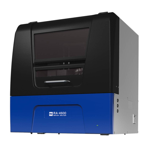
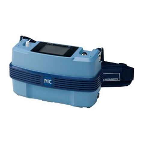
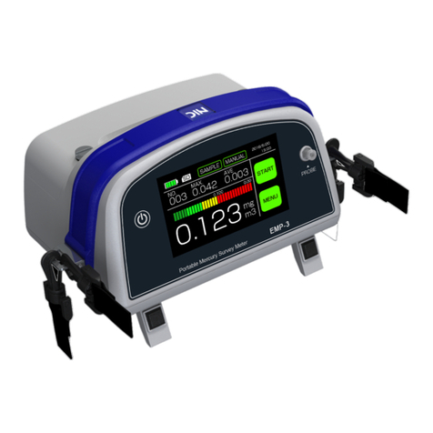
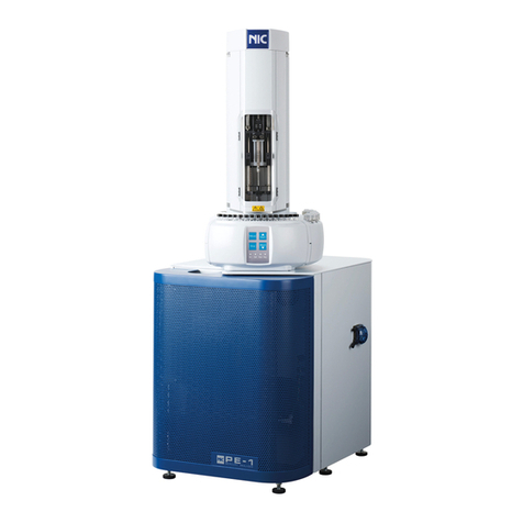
Nic PE-1 User manual

Reducing Vaporization Unit
for the PE-1
S-PE Instruction manual
NIC-TD-0000051-00
Nippon Instruments Corporation

Table of contents
1
NIC-TD-0000051-00
Reducing Vaporization Unit for the PE-1
Instruction manual
Table of contents
1. Introduction....................................................................................................................... 2
1.1. Safety precautions....................................................................................................... 2
1.1.1. Safety symbols...................................................................................................... 2
1.1.2. Installation precautions......................................................................................... 2
1.1.3. Servicing precautions............................................................................................ 2
1.2. Equipment overview .................................................................................................... 3
2. Principles .......................................................................................................................... 4
2.1. Operation..................................................................................................................... 4
2.2. Description of each component................................................................................... 5
2.2.1. Model S-PE+RH-PE......................................................................................... 5
3. Installing the equipment.................................................................................................. 6
3.1. Installation conditions .................................................................................................. 6
3.1.1. Installation environment........................................................................................ 6
3.2. Installation/connection................................................................................................. 6
4. Measurement .................................................................................................................... 7
4.1. Measuring operation flow chart................................................................................ 7
4.2. Reagents...................................................................................................................... 8
4.3. Preparation for measurement...................................................................................... 8
4.3.1. Startup................................................................................................................... 8
4.3.2. Starting the software in Windows.......................................................................... 8
4.4. Measurement............................................................................................................... 9
4.4.1. Setting measurement mode.................................................................................. 9
4.4.2. Setting the tabulation conditions......................................................................... 10
4.4.3. Procedure of Alkali-digestion ...............................................................................11
4.4.4. Preparing the calibration curve............................................................................11
4.4.5. Measuring the content of water samples............................................................ 14
4.4.6. Measurement interruption................................................................................... 16
5. Maintenance.................................................................................................................... 17
5.1. Criteria for judging equipment failure and troubleshooting ....................................... 17
5.2. Troubleshooting......................................................................................................... 18
5.2.1. Degradation of peak sensitivity........................................................................... 18
5.2.2. Abnormal blank value.......................................................................................... 19
5.3. Carrying out maintenance ......................................................................................... 20
5.3.1. Checking for leakage .......................................................................................... 20
5.3.2. Washing the coupling, joint, and gas washing bottle.......................................... 22
6. Contact ............................................................................................................................ 23

1. Introduction
2
NIC-TD-0000051-00
1. Introduction
1.1. Safety precautions
1.1.1. Safety symbols
Warning
Denotes that incorrect handling may pose a specific potential hazard,
resulting in serious injury or death to the operator.
Caution
Denotes that incorrect handling may pose a specific potential hazard,
resulting in minor or moderate injury to the operator and/or damage to
property.
1.1.2. Installation precautions
Warning
Ensure the ground wire is connected so as to prevent electric shocks.
1.1.3. Servicing precautions
Warning
Before servicing, disconnect the power supply or electric shock may occur.
Caution
Before servicing the heater section turn off the power switch and wait until the
heater has cooled down to approximately room temperature. Failure to observe
this could result in being burnt.
Be careful when working with the equipment and touching any parts made of
glass. Failure to observe this may result in damage occurring.
Only qualified persons should change the calibration curves. Using the wrong
calibration curve will result in incorrect results being obtained.

1. Introduction
3
NIC-TD-0000051-00
1.2. Equipment overview
The model S-PE, the reducing vaporization unit, is an optional device for measuring
mercury in the water with the PE-1.
In order to fully utilize the capabilities of the equipment ensure you thoroughly read this
instruction manual prior to use.
Fig. 1: Model S-PE

2. Principles
4
NIC-TD-0000051-00
2. Principles
2.1. Operation
This equipment is completely controlled from the PE-1. Selecting “RA”as the method.
In the reducing vaporization method (RAmode), bivalent mercury (Hg2+) in a solution is
reduced to elemental mercury (Hg0) with a reducing solution (SnCl2). The mercury vapor
that is generated passes through a washing bottle (where an alkaline solution
neutralizes acidic gases) and a dehumidifying bottle in series, then is collected in the
mercury collector tube as gold-amalgamation and then the mercury collector tube is
heated to release mercury.
The released mercury is detected using atomic fluorescence spectroscopy at a
wavelength of 253.7nm.
Fig. 2: Flow chart

2. Principles
5
NIC-TD-0000051-00
2.2. Description of each component
2.2.1. Model S-PE+RH-PE
Fig. 3: Picture of S-PE+RH-PE
Table 1: Description of S-PE
No.
Name
Function
Remarks
1
Impinger Inlet
Connected to “TO
COLLECTION TUBE”
Carrier gas is supplied from
the PE-1.
2
Clamp
Not to cause a leakage
3
Impinger
Optimum volume is 20mL
4
Impinger Outlet
Be connected to an empty
mercury collector tube
5
Empty mercury
collector tube
Never use a normal
mercury collector tube.
6
Impinger Stand
(1)
(2)
(3)
(4)
(5)
(6)

3. Installing the equipment
6
NIC-TD-0000051-00
3. Installing the equipment
3.1. Installation conditions
3.1.1. Installation environment
Room temperature :15°C to 35°C
Vibration :Avoid any vibrations that the human body can
strongly sense.
Dust and dirt :Maintain a clean atmosphere without any smoke,
dust, or other factors that can adversely affect
measurements. Please also refrain from smoking
anywhere near.
Installation space :A minimum area of 1,200 mm wide x 700 mm
deep is necessary. Ensure a firm foundation
(without any wobble) capable of bearing
approximately 60 kg.
Others :Avoid direct exposure to sunlight and air from air
conditioners, fans, etc.
Special notes :Never place the equipment anywhere volatile
halogen-based reagents such as organochlorine
solvents are used. In addition, avoid anywhere
such gases may be present.
3.2. Installation/connection
(1) Place Model S+RH-PE to the left of the PE-1.
(2) Connect the supplied signal cable between the PE-1 and RH-PE.
(3) Connect the power cable to the RH-PE.
(4) Connect the supplied tubes as described below.
Yellow Teflon tube
Soft PP tube
Soft PP tube

4. Measurement
7
NIC-TD-0000051-00
4. Measurement
4.1. Measuring operation flow chart
Loop
Add SnCL2 onto the
sample and close the
Impinger inner tube.
Measuring section: PE-1
Sample changer: HT-3103A
Personal computer
Reheating furnace: RH-PE
POWER ON
Optical system stabilizes
Input of measurement
conditions
Measurement starts
Heating of the mercury
collection tube
Measurement
Cooling
Termination
Injection of gas washing solution
Purge with argon gas

4. Measurement
8
NIC-TD-0000051-00
4.2. Reagents
(1) Washing solution: 0.1N NaOH
(2) Alkali-digestion (Simple digestion)
-5N NaOH
Ex. 20g of NaOH are diluted with 100mL of Distilled water.
-1000ppm of Cu2+
Ex. 394mg of CuSO4・5H2O are diluted with 100mL of Distilled water.
-10% SnCL2
Ex. Add 60mL of H2SO4(1+20) to 10mg of SnCL2and while stirring, heat it to
dissolve. After cooling dilute with Distilled water to 100mL.
4.3. Preparation for measurement
4.3.1. Startup
(1) Turn on the POWER switches of the PE-1,
the PC, and the RH-PE.
(2) Open both the roller clamps for the gas
washing bottle and the dehumidifying bottle,
and pour 0.1N NaOH solution.
Ensure the gas washing solution level is
approximately 20 mm above the air outlet.
(3) Close both the roller clamps for the gas
washing bottle and the dehumidifying bottle.
4.3.2. Starting the software in Windows
Click the icon on the desktop to start the PC software (PE1000Win).
20mm
Fig. 6: Gas washing solution level

4. Measurement
9
NIC-TD-0000051-00
4.4. Measurement
4.4.1. Setting measurement mode
Select [Run]-[Mode] from the menu, or click the
icon to set the measurement mode.
Measurement mode
Set the heating speed of the mercury collection section for measurement in accordance
with the weight of the mercury.
A guideline for that is as follows:
LOW: 0 to 10 ng (Low concentration)
The heater H5 of the mercury collection section heats up at full power, and the
mercury gas is quickly discharged into the fluorescence cell.
HIGH: 0 to 100 ng
The heater H5 of the mercury collection section slowly heats up, and the mercury gas
is gradually discharged into the fluorescence cell.

4. Measurement
10
NIC-TD-0000051-00
4.4.2. Setting the tabulation conditions
Select [File]-[Table Condition] from the menu, or click the
icon to set tabulation
settings.

4. Measurement
11
NIC-TD-0000051-00
4.4.3. Procedure of Alkali-digestion
The conventional methods require many reagents and long-time decomposition, but
this alkali-digestion technique needs no long-time digestion or many reagents.
Sample 20mL
5N-NaOH :4.0mL
1000ppmCu++ :800μL
10w/v% SnCl2:1.2mL
Aeration :8min
4.4.4. Preparing the calibration curve
(1) The settings for the standard sample are made in the Table window. Check the
“Meas” (measurement) field, and select “18:RA”in the “Method Number” field.
(2) Click the “STD”(standard value) field, and enter the concentration and the
extracted volume. The mercury weight is then automatically calculated and
entered.
(3) Enter 100uL of the standard solution 0.01ppm for example into the impinger and
then add Distilled water to 20mL. Mercury content of this solution would be
1ng/0.05ppb.

4. Measurement
12
NIC-TD-0000051-00
(4) Add the above reagents in succession and close the impinger with the inner tube
and then fix the clamp.
(5) To commence measurement, select [Run]-[Start] from the menu, or click the
icon.
Alternatively, press F5 on the keyboard to start measurement.
(6) The following message appears when the measurement is complete.
(7) To continue measurement, return to step (2) and repeat the procedure as
necessary.
(8) The calibration curve is automatically updated on completion of measurement.
Whether the sample is used for the calibration curve is specified in the “X”field.
The type of calibration curve etc can be changed in the tabulation conditions
settings.

4. Measurement
13
NIC-TD-0000051-00

4. Measurement
14
NIC-TD-0000051-00
4.4.5. Measuring the content of water samples
(1) Make the setting for an unknown sample in the Table window. Check the “Meas” field,
and select “18:RA” in the “Method Number” field.
(2) Take the sample 20mL precisely and pour it into the impinger.
(3) Add the above reagents in succession and close the impinger with the inner tube and
then fix the clamp.
(4) To commence measurement, select [Run]-[Start] from the menu, or click the
icon.
Alternatively, press F5 on the keyboard to start measurement.
(5) The following message appears when measurement is complete.
(6) To continue measurement, return to step (1) and repeat the procedure as necessary.

4. Measurement
15
NIC-TD-0000051-00
(7) Entering the amount of the collected sample into the “SVOL [mL]”(sample volume) field
after measurement automatically calculates the concentration.
The units used in the Table window can be changed in the tabulation conditions setting.

4. Measurement
16
NIC-TD-0000051-00
4.4.6. Measurement interruption
To interrupt the measurement, select [Run]-[Stop] from the menu or click the
icon.
Clicking the icon terminates operation on completion of the current measurement.
Clicking the icon immediately starts the cooling process, and the equipment
returns to READY status when cooling has completed.

5. Maintenance
17
NIC-TD-0000051-00
5. Maintenance
5.1. Criteria for judging equipment failure and troubleshooting
Listed below are criteria for judging whether the equipment is operating properly or not.
(If the equipment does not satisfy any of these criteria, take the appropriate measures
given in "Troubleshooting" described in Sections 5.2.1to 5.2.2)
(1) A blank value should be low (0.01 ng or less). →5.2.2
(2) After a mercury standard solution is measured, the blank value should not significantly
increase. (As a guide it should be approximately 1% or less of the mercury measured
right before.) →5.2.2
(3) When a mercury standard solution is repeatedly measured its reproducibility should be
within 3%. →5.2.1
(4) A calibration curve drawn using a mercury standard solution should be linear with a
variation of 5% or less. →5.2.1
(5) When a mercury standard sample is measured before and after measurement for the
water samples, the difference between the measured values should be within the
measurement error. →5.2.1
(6) The intensity of fluorescence should be at least 70% of that at the time of delivery.
→5.2.1

5. Maintenance
18
NIC-TD-0000051-00
5.2. Troubleshooting
5.2.1. Degradation of peak sensitivity
Peak sensitivity has decreased or lost.
Is any carrier gas
leaking?
Has a heater cable
broken?
Has peak
sensitivity
recovered?
Has trapping
occurred in the
system?
Locate the leak and
repair it.
Replace the relevant
heater.
Has peak
sensitivity
recovered?
Wash the gas washing
bottle and the
dehumidifying bottle.
START
END
YES
NO
YES
NO
YES
NO
YES
NO
YES
NO
Carry out maintenance of the PE-1.
Wash or replace the V5, joint, Teflon
tubes, or H5 collection tube.

5. Maintenance
19
NIC-TD-0000051-00
5.2.2. Abnormal blank value
The blank value is abnormally high (e.g. several ng) and barely decreases.
Carry out maintenance of the PE-1.
Wash or replace the V5, joint, Teflon
tubes, or H5 collection tube.
Wash the gas washing bottle,
dehumidifying bottle, joint, and
coupling.
START
END
Does the blank
value decrease?
YES
NO
Replace the transparent
Teflon tube.
Does the blank
value decrease?
NO
YES
Does the blank
value decrease?
YES
NO
Replace the septum.
Other manuals for PE-1
1
This manual suits for next models
1
Table of contents
Other Nic Measuring Instrument manuals
Popular Measuring Instrument manuals by other brands
Mollet
Mollet MOLOSwave MWF2 Series operating instructions
Landis+Gyr
Landis+Gyr UH50 Series installation instructions

PCB Piezotronics
PCB Piezotronics 356A22/NC Installation and operating manual
National Instruments
National Instruments 446 Series CALIBRATION PROCEDURE
AVL
AVL 9180 Operator's manual
SKC
SKC SoundCHEK 702 Series operating instructions


