Progeny P2 User guide

Issue 03 8-October-2007
System Hardware Manual

Issue 03 8-October-2007
Contents
1. Introduction......................................................................................1
Symbols used in this manual.............................................................................1
System Overview...............................................................................................2
P2 Product Codes..............................................................................................2
2. Software..........................................................................................3
3. Hardware.........................................................................................4
3800 P2 Reader.................................................................................................4
3801 P2 Controller & 3802 P2.net Controller ..................................................................................4
3803 P2 USB Interface......................................................................................5
P2 Credentials...................................................................................................5
3804 Proximity Card.........................................................................................................................5
3805 Proximity Key Fob....................................................................................................................5
3806 Proximity Sticky Dot ................................................................................................................5
4. Quick Start Guide............................................................................6
Objective............................................................................................................6
What you will need.............................................................................................6
Steps Involved...................................................................................................6
Connect equipment together..............................................................................7
IMPORTANT NOTE............................................................................................................................ 7
Installing Doors Express or Doors Express Professional...................................8
Use the setup wizard to scan for connected doors ............................................9
Use the setup wizard to scan for cards / fobs..................................................11
Test the cards / fobs........................................................................................14
5. Hardware Reference......................................................................15
P2 Controller....................................................................................................15
Description ..................................................................................................................................... 15
Box Contents ..................................................................................................................................15
Mounting........................................................................................................................................ 15
Lock Drive....................................................................................................................................... 15
Readers .......................................................................................................................................... 15
Door Interface Inputs ..................................................................................................................... 16
Intruder Input.................................................................................................................................16
Fire Input........................................................................................................................................16

Issue 03 8-October-2007
Supply............................................................................................................................................. 16
Network .........................................................................................................................................16
Reset Button................................................................................................................................... 16
Ethernet ......................................................................................................................................... 16
P2 Reader........................................................................................................17
Box Contents ..................................................................................................................................17
Description ..................................................................................................................................... 17
Power .............................................................................................................................................17
Mounting........................................................................................................................................ 18
Connections ................................................................................................................................... 18
Door Sensor.................................................................................................................................... 18
Request to Exit ...............................................................................................................................19
Locking Device................................................................................................................................19
Led’s ............................................................................................................................................... 19
P2 USB Interface.............................................................................................20
Description ..................................................................................................................................... 20
Box Contents ..................................................................................................................................20
Mounting........................................................................................................................................ 20
Connections ................................................................................................................................... 20
USB 2.0 Interface............................................................................................................................ 21
P2 Network.....................................................................................................................................21
Desktop Reader.............................................................................................................................. 21
LED Indicators.................................................................................................................................21
6. PC.................................................................................................23
PC Selection....................................................................................................23
Doors Express & Doors Express Professional PC Selection Guide.................23
Single PC......................................................................................................................................... 23
Server PC ........................................................................................................................................ 23
Client PC ......................................................................................................................................... 23
Features Used ................................................................................................................................23
PC specification...............................................................................................24
7. Specification..................................................................................25
SOFTWARE ....................................................................................................25
STANDARD PROFESSIONAL.........................................................................................................25
CONTROLLER................................................................................................25

Issue 03 8-October-2007
ETHERNET (P2.net Only)................................................................................................................. 25
NETWORK....................................................................................................................................... 25
FUNCTIONS .................................................................................................................................... 25
INTERFACE......................................................................................................................................25
READER..........................................................................................................26

1
1. Introduction
The Progeny P2 system is an exciting new addition to the Progeny range of access control products. It has
been specifically designed for installations between one and sixteen doors. Simplicity was the key design criteria
for both for hardware and software. The software interface of Doors Express and Doors Express Professional
provides a setup wizard which will have the P2 system up and running in five simple steps! For ease of use, the
P2 setup wizard will search for doors on the P2 network and add them automatically as well as allowing the user
to easily add cards to the system.
The P2 system offers two methods of connectivity to a PC:
USB Interface via a 3803 P2 USB Interface
Local Area Network via a 3801 P2.net.
This manual provides a “Quick Start Guide”to set the system up in simple steps and also a more in depth guide
to the hardware of the P2 system. For a more detailed look at the software and its features refer to the “Doors
Express Software Manual”.
Symbols used in this manual
Reference markers; link text descriptions to diagrams.
Sequence markers; indicate major steps in a sequence.

2
System Overview
Figure 1
P2 Product Codes
3800
P2 Reader
3805-10
P2 Proximity Key fob (10 Pack)
3801
P2 Controller
3805-100
P2 Proximity Key fob (100 Pack)
3802
P2.net Controller
3806-10
P2 Proximity Sticky Dot (10 Pack)
3803
P2 USB Interface
3806-100
P2 Proximity Sticky Dot (100 Pack)
3808
P2 Doors Express Software
3804-10
P2 ISO Proximity Card (10 Pack)
3809
P2 Doors Express Pro Software
3804-100
P2 ISO Proximity Card (100 Pack)

3
2. Software
“Doors Express” has a fantastic new design with a simple to use interface. Users
can quickly learn the features of the P2 system. Doors Express provides you with
many features including:
Card Manager for quick and simple card holder management.
Comprehensive sorting and filtering with effective quick searches. Create custom
database fields to suite your needs.
Photo ID printing, allows for simple (fixed design) landscape or portrait ID cards. Upgrade to
professional version of Doors Express for custom card design.
Access Levels for effectively managing access.
Space Zones keep track of occupancy of selected areas. Most commonly used for “Roll Call” reporting.
Triggers allow selected events to be notified by on screen alarms.
Time Zones; are flexible time switches that can be assigned to:
oOpen doors (Free Vend) for set times of the day
oRestrict access levels to defined times of day and days of week
oOperate spare relays to give general purpose time switches
Calendars; extend the control of time zones by specifying exception dates. Dates can be planned years
in advance.
Event Viewer’s provide a comprehensive monitoring and reporting facility. Simple point and click “Who,
What, Where and When” reporting. Print or export the data as you need.
Automated Backup and event data archiving. Setup schedule for backups so they cannot be forgotten
and protect against data loss.
Dormant card policy; automatically disables unused (forgotten) access cards / fobs.
“Doors Express Professional”expands on Doors Express by adding additional
features such as:
“ID Badge Design”allowing users to create their own card designs for
printing Photo ID cards
Graphical Floor Plan Alarms which allows the user to create a plan of
the building and place the access controlled doors on these plans. Alarms can
then be shown graphically on screen to indicate where a problem is located.
“Zoned Anti-pass Back; helps enforce the correct usage of cards on the system.
Card Data Import facilities for bringing in data from other sources such as a Microsoft Excel
spreadsheet

4
3. Hardware
3800 P2 Reader
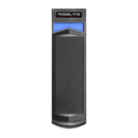
The following diagram shows both the front and back of the reader. The reader comes supplied with an optional
steel cover for vandal resistant use along with a surface mounted back box. The reader can also be flush
mounted (recommended) to an existing flush mount single gang switch box.
Figure 2
3801 P2 Controller & 3802 P2.net Controller
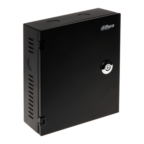
Both these controllers are supplied in a simple metal enclosure with cable entry points on each of the four sides
and two in the back.
Figure 3

5
3803 P2 USB Interface
Figure 4 shows the front and rear view of the P2 USB Interface. The USB Interface comes with a surface
mounted back box with access for the USB connector at the bottom edge.
Figure 4
P2 Credentials
3804 Proximity Card
The P2 Proximity Card is a passive RFID ISO proximity card for use with P2 systems. The card is credit card
size and can be comfortably stored in a wallet or purse. The ISO proximity card is suitable for card printing
enabling them to also serve as an identity card.
3805 Proximity Key Fob
The P2 Proximity Key fob is a passive RFID proximity credential which conveniently fits on a key ring (not
supplied) which is ideal for applications where keys are carried at the point of access or where a more robust
credential is required.
3806 Proximity Sticky Dot
The P2 Proximity Sticky Dot is a passive RFID proximity credential which can be attached to the rear of mobile
phones or other hand held devices. The dots are ideal if you wish to use existing identity cards as credentials for
access, simply attach a dot to the rear of the identity card.
00000360
00000077
00000738

6
4. Quick Start Guide
Objective
The purpose of this guide is to build a basic single door access control system enable a single card / fob to
release a lock. With this in place you can then experiment adding doors, cards, disabling access and interacting
with the live system.
What you will need
P2 Controller
12V power supply.
P2 Reader.
P2 USB Interface
PC running Windows Vista, XP Pro SP2 or 2000 SP4.
Doors Express installation CD.
Steps Involved
Connect equipment together
Install the Doors Express
Use the setup wizard
Use the setup wizard
Test the cards

8
Installing Doors Express or Doors Express Professional
Insert the Doors Express CD. The setup screen should load automatically. If auto play is turned off on your PC
and the setup screen does not start automatically, you can run autohtml.exe which can be found on the
installation CD here:
<CD drive letter>:\web\autohtml.exe.
Select the single workstation option by clicking on “single workstation”:
Follow the onscreen instructions (install Microsoft SQL 2005 Express first then Doors Express). The computer
may need to restart after successful installation.
Once this is complete use the second option in Figure 6 to install Doors Express.
Figure 6

9
Once installation is complete, the login screen for Doors Express will appear.
Simply enter the default password “654321” and press <Enter>. The software will detect the fact that the system
is being started for the first time and automatically start the “Setup Wizard”.
Use the setup wizard to scan for connected doors
The wizard will also at this stage ask you to connect your P2 USB adapter for the first time.
(When connecting the USB cable to the PC, the system will automatically install the drivers for the USB network
device, so wait 20 seconds before continuing.)

10
Select the connectivity option for USB. The wizard will automatically search for all connected doors and display
the doors found.
Click ok and confirm that all the doors have been found (if a door is missing from the list that you have fitted,
check the network wiring for faults or loose connections). After checking the doors in the list are correct, click
next.

11
Use the setup wizard to scan for cards / fobs
The wizard will now ask you if you wish to add cards to the system.
Check the yes box to add the cards and click on “next”.

12
Change the “Read card ID from” to the name of the door just added.
Then present a test card to the reader connected to the P2 controller. The Card ID will be displayed in the “Card
ID” box. This will match the number printed on the card or fob.
Enter a name for the holder of this card.
Check the enabled box.
Select the default “All Doors” access level
Click on “add card details” then click on “Next”.

14
Click “finish” to confirm the additions to the system or click “cancel” to discard the additions to the system.
You can choose to run the wizard again at any time by clicking on the Doors Express System Manager icon and
clicking the “start the setup wizard” link.
Test the cards / fobs
This completes the basic P2 system setup. By following the instructions above you will now have a simple door
access control system allowing access for a single valid card. Because we enabled the card and gave it an
access level “All Doors” the card will be valid at all the doors on the system.
To see how to add more doors, cards and to control access permissions see the “Doors Express Software
Manual”. This can be accessed from the help menu of the Doors Express software.

15
5. Hardware Reference
P2 Controller
Description
The P2 and P2.net Controllers are single door controllers for use with the Progeny P2 access control range. P2
uses a revolutionary reader interface that allows most door functions to be handled over a single 4 core
unscreened cable. The controller is completely programmed from a PC using the Doors Express software.
Box Contents
1 x P2 Controller or P2.net Controller mounted in a 165mm x 145mm steel enclosure (black)
1 x Hardware Manual
Mounting
The P2 Controller and its power supply should be mounted in a secure location. This should ideally be as close to
the door as possible (Max 100m cable run) to avoid volt drops.
Figure 9
Lock Drive
There are two voltage free relays (A & B) on the P2 Controller for operating locking devices.
The green LEDs labelled “RLY” illuminate when the relays have been activated.
Readers
The controller has 2 proximity reader channels for use with P2 readers only. Reader A is designated out and
Reader B is designated in. The P2 Readers are connected to the P2 Controller using a standard 4 core cable
(alarm cable is suitable).
The readers LED’s indicate:
Green flash = Data from the card reader.
Red = Overload on the supply to the reader (> 200mA Possible short circuit).

16
Door Interface Inputs
The P2 Controller has two inputs for door interface devices:
Door sensor input (DR), Normally closed contacts (Closed when the door is closed).
Request to Exit input (RQE), Normally open contacts of a push button switch.
Intruder Input
This is a monitored input, and comes fitted with a 1K resistor. When interfacing to a fire intruder alarm system or
tamper switch normally closed contact this resistor should be moved to be in series with the contacts at the alarm
system end. This allows short circuit faults to be detected and reported.
LED by this input:
Red = Fault (Short circuit)
Green = Alarm (Open circuit)
Dark = Normal (Standby)
Fire Input
This input is configured to automatically operate Relay A. This allows an interfaced fire alarm system to open the
door in case of emergency.
This is a monitored input, and comes fitted with a 1K resistor. When interfacing to a fire alarm normally closed
contact this resistor should be moved to be in series with the contacts at the fire alarm system end. This allows
short circuit faults to be detected and reported.
LED by this input:
Red = Fault (Short circuit)
Green = Alarm (Open circuit)
Dark = Normal (Standby)
Supply
The P2 Controllers require a 12V DC PSU (not supplied). The actual operating range is between 10V DC and
14V DC. The status LED next to the reset button indicates whether the board has power or not.
Network
A single twisted pair cable is to be used to wire the P2 Network (a screened cable can be used to offer better
protection). If the optional screened cable is used then the incoming and outgoing screen can be connected to
SCR on the Network terminals. It is important to remember that the screen needs to be earthed to ground at one
end of the network to be effective.
The End of Line Resistor jumper is set to N as default. This should be changed to Y if the P2 Controller is the
first or last controller on the daisy chain network.
LED by this input:
Red = Network data packet
Green = Response packet from this controller.
Reset Button
The controller can be reset to factory defaults by pressing and holding the reset button for 3 seconds.
LED by this button:
Red = Fault: Supply voltage > 14.5V or < 9.5V
Green flash (one per second) = Normal P2 heartbeat.
Ethernet
Additional 3801 P2 Controllers can be added to the system by linking them together in a daisy chain using the P2
Network. Doors Express will support a maximum of 16 controllers per system.
Other manuals for P2
1
This manual suits for next models
12
Table of contents
Other Progeny IP Access Controllers manuals


