MCX402-BRD Operating Manual 04.12.2020
installations subject to strong electromagnetic interferences. The RS485 communication standard used in
the RACS 5 system guarantees proper communication in a distance of up to 1200 meters as well as high
resistance to interferences.
Note: Do not use more than single pair in UTP cable for RS485 communication bus.
Wiegand bus
Wiegand interface can be used for communication with third party readers and terminals. Wiegand
communication is ensured via expander input lines (IN1-IN4) and up to two Wiegand terminals can be
controlled in such way by MC16 controller.
RACS CLK/DTA bus
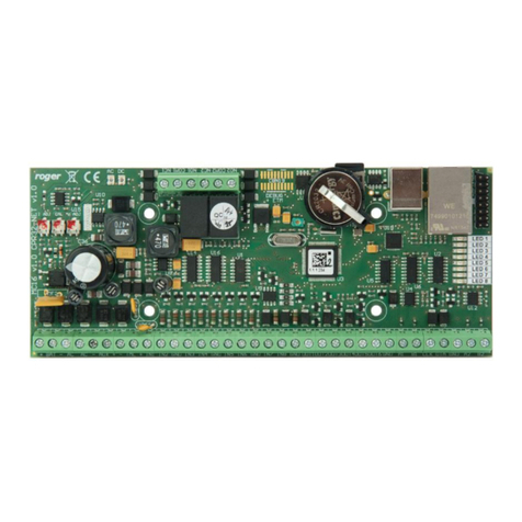
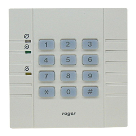
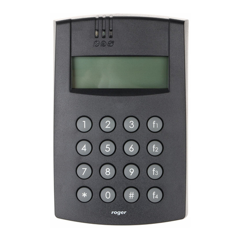
The expander with factory uploaded firmware enables operation of Wiegand terminals with MC16 controller.
In case of PRT readers with RACS CLK/DTA interface the expander must be uploaded with new firmware
which is available at www.roger.pl. The expander enables the control of two PRT series readers with ID=0
and ID=1 addresses by MC16 controller.
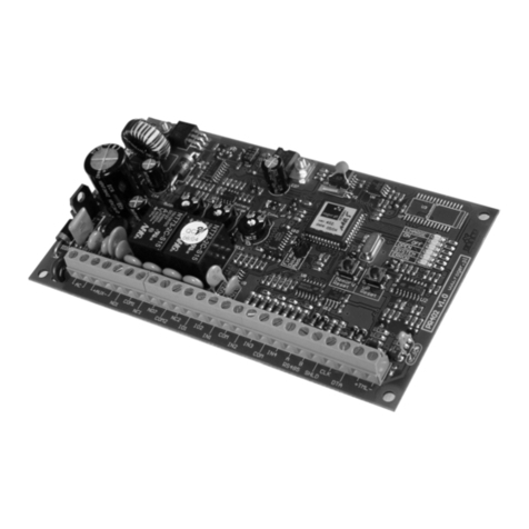
LED indicators
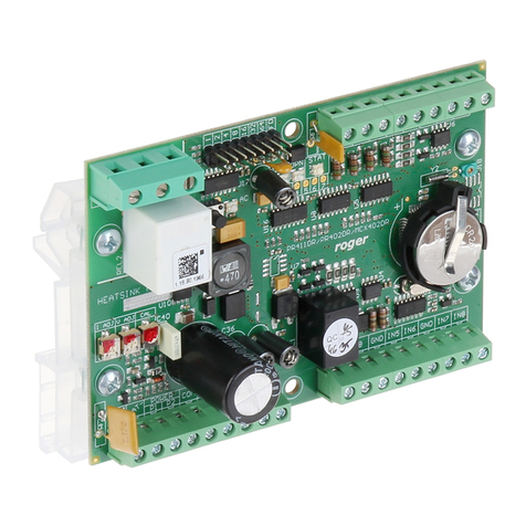
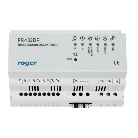
Expanders are equipped with LED indicators which are used to signal integral functions.
Current arming mode of Alarm Zone (armed/disarmed)
Various signalling functions including errors
Data transmission on RS485 bus
Inputs
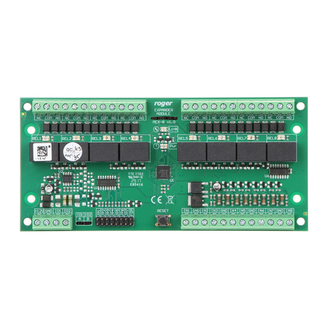
Expander offers 8 inputs (IN1 - IN8) of NO and NC type. Input types are defined within low level
configuration (RogerVDM). Input functions are assigned within high level configuration (VISO). Multiple
functions can be assigned to the same input at the same time.
Outputs
Expander offers two transistor outputs (IO1, IO2) and two relay outputs (REL1, REL2) with NO/NC contacts
and respectively 30V/1,5A and 230VAC/5A max. loads. Electric parameters such as polarity are configured
within low level configuration (RogerVDM). Function are assigned to outputs within high level configuration
(VISO). Multiple functions with different priorities can be assigned to the same output at the same time.
Power supply outputs
Expander offers 2 outputs (AUX, TML) in order to provide power supply to terminals, door lock and other
external devices. Lines are protected respectively with 1.0A and 0.2A electronic fuses.
2. INSTALLATION
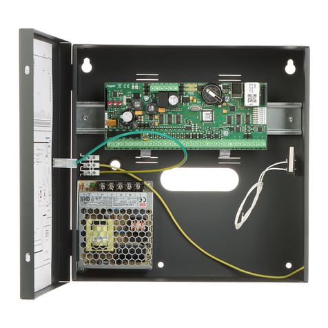
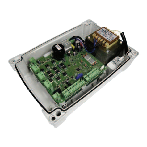
Each expander is equipped with a holder for installation on DIN35 rail. Therefore expanders can be installed
in ME type enclosures equipped with such rail. Alternatively, expanders can also be mounted using screws
and holes on expander board. It is recommended to install the expander in the same enclosure as PSU.
