Proxxon FF 500 CNC Quick start guide

Commissioning Manual
FF 500 CNC

2 of 55
FF 500 CNC Commissioning Manual
1. Some generalities in advance…...................................................................................4
2. The technology of your FF 500 CNC at a glance .........................................................5
2.1. A short overview of the mechanics:..........................................................................5
2.2. A short overview of the electronics:..........................................................................6
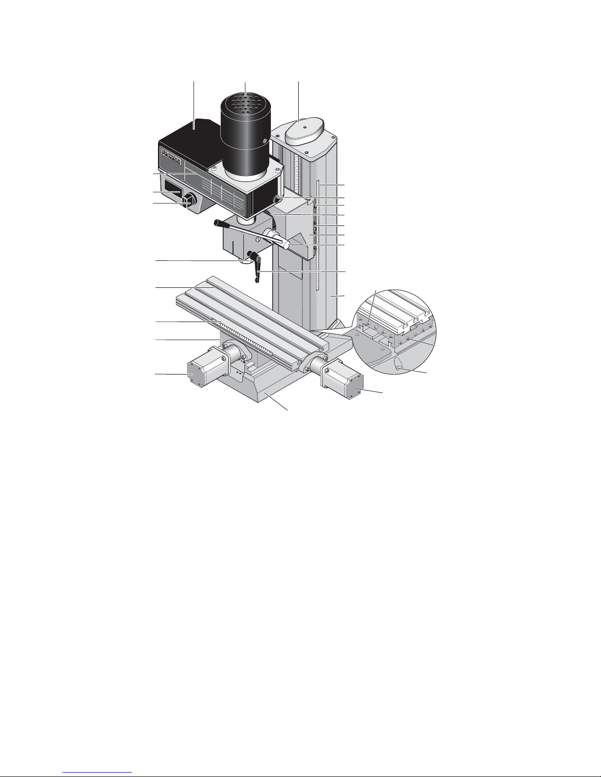
3. View of the machine with its elements..........................................................................8
4. CNC control MCS with operating elements ..................................................................9
5. Technical data ............................................................................................................10
5.1. Milling machine:......................................................................................................10
5.2. Drives of the tool axes ............................................................................................11
5.3. Software and stepping motor controllers ................................................................11
5.4. Further data ............................................................................................................12
5.5. Milling cutter dimensions ........................................................................................12
6. Scope of delivery ........................................................................................................12
7. Basic tips on setting up and installing the machine ....................................................13
7.1. Unpacking and setting up the machine ..................................................................13
7.2. Connecting the cabling ...........................................................................................15
7.3. Additional connection options.................................................................................16
8. Installing the software.................................................................................................17
8.1. Minimum hardware requirements ...........................................................................17
8.2. Installation procedure .............................................................................................17
8.3. Starting the software nccad7.5 ...............................................................................18
8.4. Parameter settings .................................................................................................18
8.5. The status display at the CNC control MCS ...........................................................18
8.6. EMERGENCY stop / lock .......................................................................................19
9. The program nccad 7.5 milling ...................................................................................20
9.1. The integrated manual with the help system ..........................................................20
9.2. The structure of the "Help topics" window ..............................................................21
9.3. Search methods .....................................................................................................21
9.3.1 Contents .............................................................................................................21
9.3.2 Index...................................................................................................................21
9.3.3 Search ................................................................................................................21
9.3.4 Explanation of the icons and the Status bar .......................................................22
9.4. Online support ........................................................................................................22
10. Important note for working in practice ........................................................................23
10.1. Simple stopping of the machine and the Emergency-Off switch ........................23
10.2. Safety stop, lock .................................................................................................23
10.3. Direction of rotation switch..................................................................................23
10.4. Room EMERGENCY Off ....................................................................................23
11. First steps ...................................................................................................................24
11.1. Simple test of the machine .................................................................................24
11.2. Semi-automatic operation: Traversing the CNC axes with the cursor keys........25
12. Working with the milling cutter....................................................................................26
12.1. General information for working with milling cutter .............................................26
12.2. Working with the drilling lever .............................................................................27
12.3. Swivelling the milling head by its own transverse axis .......................................28
12.4. Mounting the collet chucks .................................................................................28
12.5. Changing the spindle speed ...............................................................................30
12.6. Milling..................................................................................................................32
12.7. Feed:...................................................................................................................32
13. Accessories ................................................................................................................33
14. Repair, Cleaning and Maintenance ............................................................................34
14.1. In general............................................................................................................34
14.2. Replacing the drive belt ......................................................................................35
14.3. Adjusting the play of the cross table or Z carriage guides..................................36

3 of 55
14.4. Lubricating the machine......................................................................................36
14.5. Cleaning and care...............................................................................................37
15. Disposal......................................................................................................................38
16. Errors and their removal .............................................................................................39
17. Compilation of safety notes: .......................................................................................41
18. EC Declaration of Conformity .....................................................................................43
19. List of components and exploded views.....................................................................45
19.1. General view.......................................................................................................45
19.1.1 General view exploded drawing and parts list ................................................45
19.1.2 Exploded drawing and parts list Assembly group 01:Z axis ...........................47
19.1.3 Exploded drawing and parts list Assembly group 02 Drive Y axis..................49
19.1.4 Exploded drawing and parts list Assembly group 03 Drive X axis..................51
19.1.5 Exploded drawing and parts list Assembly group 04: Milling head.................53
Ver. 1.0
16.09.08

4 of 55
1. Some generalities in advance…
Dear Customer!
The information given in this manual and the knowledge it conveys is indispensable
for the safe commissioning and the safe operation of the machine and the controls!
Before you set up and commission your machine, please read through the manual
and make sure you have understood everything. This is a very complicated device
which poses the danger of injury or can cause damage to property if handled
improperly.
Help to prevent this and familiarise yourself thoroughly with the machine and its
associated electronics without rushing matters.
The use of these instructions
-makes it easier to become acquainted with the device,
-prevents malfunctions due to improper handling, and
-increases the service life of your device.
Always keep these instructions close to hand.
Only operate this device with exact knowledge of it and comply with these
instructions.
PROXXON will not be liable for the safe function of the device for:
-handling that does not comply with the usual intended use,
-other application uses that are not stated in these instructions,
-disregard of the safety regulations.
You will not have any warranty claims for:
-operating errors,
-lack of maintenance.
For your safety, please comply with the safety regulations without fail.
Only use original PROXXON spare parts.
All rights reserved for further developments within the meaning of technical progress.
We wish you much success with the device.

5 of 55
2. The technology of your FF 500 CNC at a glance
Dear User,
With this FF 500 CNC vertical miller, you have acquired a powerful, precise
processing machine that fulfils the highest demands on ease of use, precision and
reliability. In the following, you will find explanations on some of the technical details:
2.1. A short overview of the mechanics:
The FF 500 CNC is a solidly constructed and carefully manufactured upright vertical
milling machine. The equipment compiled in a user-friendly manner and the
extraordinary quality of the design make the milling cutter a reliable partner for an
entire series of activities from the machining sector.
A heavy, rugged machine base ensures excellent stability and accommodates the
CNC-controlled cross table, traversable in two axes (diagonal (X axis) approx. 300
mm, deep (Y axis) 100 mm) as well as the sturdy and generously dimensioned
column made of high-strength aluminium continuous casting profile. Just like the
cross table, it is equipped with a dovetail guide which supports the carriage to
accommodate the milling head.
This carriage is also traversed by electronic control, and the traverse path (Z axis) is
approx. 220 mm. The milling head itself consists of the motor, the gearbox and the
spindle unit. If required, it can also be turned by 90° on each side and conveniently
clamped in any position with the toggle screw. Together with the drilling feed, this
makes slanted drilling possible, for example. The tool is held in one of the four
supplied collet chucks.
In addition, the milling head is equipped with a drill feed, which means that your
milling cutter can also be used for drilling work or for countersinking, for example.
The electrical system and the belt drive for power transmission are housed within the
gearbox. By simply shifting a Poly-V belt it is possible to adapt the spindle speeds to
different milling sizes and material-specific cutting speeds (six selectable speeds
from 180 - 2,500/min). The master device switch and the changeover switch for the
spindle direction of rotation are located at the front of the milling head.
The high-precision dovetail guides are adjustable for all axes in order to eliminate
possible play due to wear. You will find a dimensioned sketch of the machine
dimensions and the slot cross-sections (Fig. 1 and 2) on the left and at the end of the
text.
A comprehensive range of accessories is available in our assortment.

6 of 55
2.2. A short overview of the electronics:
The electrical control of the feeds of the three tool axes by computer
comprehensively expands the options of a conventional, i.e. manually controlled
processing machine:
The geometrical data of the desired work piece shape is constructed or programmed
by the NCCAD 7.5 software especially developed for this machine and can then be
reproduced automatically and any number of times on the FF 500 CNC.
How does this work in detail?
For a conventional tool machine, the carriage or the cross table would have to be
"cranked back and forth" manually using the handwheels in order to create the
desired contour from the blank with the miller or cutting chisel.
The feed movements of CNC machines are principally generated by electric motors
(so-called stepping motors with high resolution for the best processing accuracy and
reliability) and high-precision recirculating ball screws, which "translate" the rotation
of the motor shaft to a back-and-forth movement of the respective carriage.
However, someone must tell the motors how far they must traverse the tool and/or
carriage at what time and in which direction, so that the desired work piece shape
emerges.
This communication is assumed by the connected computer together with the
control. This control converts the "path information" given by the computer into
performance data for the motors.
The final work piece must be "constructed" in the computer first. Special computer
programs are available for this. After the part was created in the computer, the
programs can even calculate which motor on the machine must turn for how long and
how quickly so that the movement of the work piece holder corresponds exactly to
the one that would have had to been "cranked through" manually.
That is why the computer, the controller and the motors are constantly
communicating with each other: Meticulous adjustment of the components amongst
each other is thus decisive to achieve the optimum performance and offers the basis
for trouble-free operation.
To keep this state, certain knowledge of how the machine and the software are set
up is required on the one hand and the interaction of these components on the other.
That is precisely what this manual should convey at first: Not primarily the instruction
into the many "secrets" of the CNC program, but rather a solid knowledge base on
the commissioning of the machine.
Naturally, it is also necessary to generally occupy oneself with the possibilities of the
program and its structure, simply to be able to use the many possibilities, be more
efficient and to prevent dangerous situations from occurring.
We have integrated an "electronic manual" within the program just for that purpose. It
contains all the necessary information in a clearly structured and comprehensively
illustrated form and goes into exhaustive detail of the possibilities offered by the
program.

7 of 55
This is called up by clicking the "Help" menu and then clicking "Help Topics" in the
next window.
Finally, this manual can be used as a "Help" function to solve quite concrete and
current problems with an application, using the help of a sophisticated navigation
window.
This omits the annoying paging back and forth in a voluminous printed work: the
answers to specific problems are found quickly and precisely.
You will find notes on how to use the "Help" function further along in this manual.
Furthermore, we offer specific notes on what you can do to not only use the excellent
features of the machine, but to maintain it for a long time.
If a malfunction occurs despite all these things, the error table at the end of this
manual will provide some help. We will also offer direct assistance in case of
particularly stubborn cases.
The schematic illustration below shows the structure and the "interconnection" of the
individual components. The software that enables us to digitally construct the parts
and generate the "running commands" is installed on the computer at the bottom left.
Naturally, a notebook or laptop are more suitable as a "computing centre". These
stay mobile and it is not necessary to put a normal computer next to the machine in
your hobby basement or workshop.
The computer is connected by RS 232 connection to the control unit (we call it the
MCS multi-controller), and the electrical components of the machine are connected
to it in turn. All of the necessary connecting cables with matching plugs are supplied
and only need to be plugged in.

8 of 55
3. View of the machine with its elements
Material
Werkzeug
durchmesser
Ømm
- 4
4-10
960
630
420
210
1880
960
630
210
210
1880
960
630
210
210
10-20
20-30
30-40
Stahl Aluminium Kunststoff
1172
3
5
4
16
21
19
22
8
6
9
10
18
7
11
12
13
23
14
25
20
15
24
Fig. 1: Overall view of the milling cutter
1. Motor 14. Z carriage/milling head fixture
2. Covering cap 15. Handwheel for X direction
3. On/Off switch 16. Handwheel for Y direction
4. Direction of rotation changeover
switch
17. Handwheel for Z direction
5. Table 18. Clamping screw for height
adjustment
6. Knurled screw for covering cap 19. Work table (400 mm x 125 mm)
7. Swivel nut for collet chuck 20. Screw holes for fastening
8. Clamping screw for quill 21. Base
9. Adjustable scale for depth
adjustment
22. Support
10. Adjustable scale for lateral traverse
path
23. Adjusting screws for X guide
11. Scale for angle adjustment 24. Adjusting screws for Y guide
12. Drilling lever 25. Adjusting screws for Z guide
13. Column

9 of 55
4. CNC control MCS with operating elements
Fig. 2: Front side
Fig. 3: Rear
Handwheel plug connections Status indicator "Emergency Stop" lock switch
Connection for
communications
cable to PC
25-pin plug for controlling
the additional functions
(coolant pump, or similar)
Mains
connection
Connection for
milling cutter
mains connection
Master switch
Connection sockets for
the stepping motor
plugs
Connection for stepping
motor
USB connection
(for programming the
controller hardware)

10 of 55
5. Technical data
5.1. Milling machine:
Voltage: 220 - 240 Volt, 50/60 Hz
Capacity: 400 Watt
6 spindle speeds by
shifting the belt:
180, 350, 550, 800, 1,300 and 2,500/min
Basic dimensions see Fig. 2
Quill feed: 30 mm using drilling lever with scale ring (1
graduation line = 1 mm).
Cross table solid, surface-milled cross table with 3
continuous T-slots for size 8 standard bricks
Slot clearance: 45 mm
Slot cross-section see Fig. 3
Table size 400 x 125 mm
Tool holder 6, 8, 10 and 12 mm collet chucks (included in
delivery).
Milling head can be pivoted to the left and right by 90° (with
degree graduation).
Extension (column outside
to centre of tool)
approx. 125 mm
Column of high-strength aluminium continuous casting,
extensively ribbed to achieve optimal strength
Noise generation ≤70 dB(A)
Vibrations ≤2.5 m/s²
Weight approx. 50 kg

11 of 55
5.2. Drives of the tool axes
Spindle drive X axis
(Longitudinal drive, cross table):
Recirculating ball screw with 4 mm pitch, effective
diameter 12 mm. Stepping motor 2.2 A, holding torque
1.27 Nm, traverse path: approx. 290 mm
Spindle drive Y axis
(Transverse drive, lower carriage):
Recirculating ball screw with 4 mm pitch, effective
diameter 12 mm. Stepping motor 2.2 A, holding torque
1.27 Nm, traverse path: approx. 100 mm
Spindle drive Z axis
(Leading spindle, longitudinal drive,
support):
Recirculating ball screw with 4 mm pitch, effective
diameter 12 mm. Stepping motor 2.2 A, holding torque
1.27 Nm, traverse path: approx. 220 mm
5.3. Software and stepping motor controllers
Power supply Input: 230 Volt +-5%
Mains unit: output 35 V (included)
Power consumption min 150 Watt
Gate Serial interface - Connection cable to PC included
Stepping motor controller Through CNC control unit (included) current control,
pulse width modulation
Current reduction during standstill, clocking independent
of PC, microstepping

12 of 55
5.4. Further data
Ambient conditions: 5 - 40°C (Class 3K3), max.60% relative humidity
User group Persons as of 14 years of age
5.5. Milling cutter dimensions
6. Scope of delivery
1 Qty. Milling cutter with attached stepping motors
1 Qty. CNC control unit MCS
1 Qty. CD with program software (including electronic manual)
1 Qty. Mains cable for CNC control unit MCS
1 set of connecting cables for computer / CNC control unit MCS
1 set of operating tools
1 set of commissioning manual and safety regulations
1 set of collet chucks Ø 6, 8, 10 and 12 mm incl. swivel nut

13 of 55
1
2
7. Basic tips on setting up and installing the machine
7.1. Unpacking and setting up the machine
Caution!
Do not insert the mains plug before completing the assembly work as the machine
could be switched on unintentionally. Risk of injuries!
Carefully unpack the individual components from the Styrofoam packaging. Please
check for completeness of the delivery by using the list in the chapter "Scope of
Delivery".
Caution! Please assemble the drilling lever (item 12 in the "Overall view of the milling
cutter) to the drilling lever shaft!
Caution!
Your milling machine weighs approximately 50 kg. Please do not attempt to lift the
machine out of the box by yourself or even set it up alone! Ask someone to help you,
otherwise you risk hurting yourself or damaging the machine.
The machine may only be set up and operated in dry and well-ventilated rooms. The
configuration of the components and its cabling is illustrated in the schematic figure
in Chapter 2.
The setup site must be level and sufficiently stable to absorb the vibrations that occur
during work. The machine must be fastened
to a fixed, level underlay using the drill
holes intended for this purpose.
Please make sure the mains cable is
outside the hazard area and cannot be
crimped or otherwise damaged.
For safe and precise work, it is mandatory to
fasten the machine onto a sturdy workbench or
similar working support, see figure at right.
There are two drill holes 2 for two M8
Allen screws on the right and left in the
machine base 1 for this purpose.

14 of 55
Please note:
At delivery, some of the blank metal parts of the machine are conserved with
corrosion protection. This protection is not intended as lubrication but only as
conservation and must be removed before first use, such as with a lint-free cloth
saturated with petroleum.
All guides must be checked, and in rare cases adjusted as necessary. (See chapter
"Maintenance").
The blank guides and spindles must then be oiled with suitable machine oil.

15 of 55
7.2. Connecting the cabling
How to connect the devices to each other is illustrated in the schematic sketch.
Caution!
Connect the mains cable to the CNC control MCS and to your computer at the very
last and make sure the mains switch at the rear of the CNC control is set to "O",
meaning switched off! Do not in any case switch on any electrical device, be it the
computer, the CNC control, or the machine itself before the connection of the cables
is completed!
The connection
sockets on the CNC
control are all located
at the rear of the
housing:
The connection cable
of the three stepping
motors is inserted in
the provided sockets of
the CNC control. They
are identified
accordingly as "X", "Y"
and "Z" of the
respective CNC axes.
For your information:
The "implied" X axis is
horizontal in the
longitudinal direction of
the cross table, the Y
axis is also horizontal
but at right angles to
that, and the Z axis
describes the vertical
traversing of the milling head at the column.
The mains cable of the milling machine is inserted in the provided socket at the rear
of the CNC control. The spindle motor is switched on and off by the CNC programs.
Please leave the insertion of the mains plug of the computer and the CNC control in
the mains socket outlet for the very last.
The communications cable included in the delivery is used to connect the CNC
control to the control computer. It is inserted in the appropriate socket at the control
and connected to a serial interface at the computer.
These are often called "serial" or "COM" and usually have 9 pins. If the connection at
your computer has 25 pins instead of 9, you will need a corresponding adapter.

16 of 55
7.3. Additional connection options
Several additional functions can be electronically
actuated upon request, such as a coolant pump, working
light, or similar.
The inside of the control has centre-zero relays whose
connections can be executed through the 25-pin socket
at the rear of the control. Each relay has three pins that
are identified by the letters A, R and G. These letters
stand for:
A: Make contact
R: Break contact
G: Common contact
The circuit design mode of operation is illustrated in the
picture on the right; both Relays 3 and 4 are available.
Ground
+ 24 Volt
Make contact
Common
Brake contact

17 of 55
8. Installing the software
8.1. Minimum hardware requirements
The NCCAD software is very comprehensive and powerful, therefore there are
certain minimum requirements towards the utilised control computer:
Simple operation and controller PC:
• Windows 98/2000/XP
• RAM: at least 16 MB
• Free hard disk capacity: at least 60 MB
• Graphics resolution at least 1024 x 768 pixel
Extended functionality (OpenGL simulation, manual control):
• Graphics resolution at least 1024 x 768 pixel
• Fast graphics card with chipset, at least Gforce4 or similar
8.2. Installation procedure
The software is included
on the enclosed CD.
After the CD is inserted
in the drive, the Explorer
will display the following
image:
Double-click the
"Installation" directory,
then "English", "01
Standard" and finally
"Setup Standard". This
starts the installation
procedure. Simply follow
the entry instructions.
The program is now
written to a directory
called "Kosy 75" that
contains the necessary
files. The program icon will be installed automatically to your desktop.

18 of 55
8.3. Starting the software nccad7.5
After the program was successfully installed, it can be started just as you are used to
from other applications on your computer. Simply select the "Start" button on the
screen with your cursor and select the desired file in the program title bar. It's even
easier if you simply click the program icon.
8.4. Parameter settings
The specific machine data (travel paths, limit values, working conditions, equipment,
etc.) are stored in the parameter files. These can be recognised by the ending "*.ini"
in the Windows Explorer.
Caution!
The values stored there are especially adapted to operation with the FF 500 CNC
and should not be changed without experience and knowledge of the program.
No changes may be made here especially before commissioning! False entries can
lead to system errors and dangerous operating states!
8.5. The status display at the CNC control MCS
There are three different coloured lights on the panel of the
CNC control; see picture. They indicate the operating status of
the CNC milling cutter.
•Yellow: Caution (Achtung) (in action) – command
execution running, even if the axis or spindle are not
currently moving. Do not reach into the CNC machine;
it is possible that the command "pause" is running
down and machining can continue at any time.
•Green: Free (Frei) (to receive commands) – Communications with the
PC is possible, commands can be received.
•Red: Locked (Gesperrt) (or error) – The movement and command receipt of
the CNC machine are locked. This could be the case if the EMERGENCY stop
was activated, or if an error occurred in the system (e.g.: communications
error, PC no longer completely functional).
•All: After the CNC milling cutter is switched on as a lamp test for a duation
of approx. 1 second.

19 of 55
8.6. EMERGENCY stop / lock
The EMERGENCY stop is used to lock the CNC milling machine
for command receipt and for command execution. Only the red
status lamp will light up in the "Lock" (Sperren) position. The lock
can be useful, for example, to prevent the execution of a
movement command that was entered unintentionally.
The lock is removed when the switch is set to "On" (Ein) and the
CNC milling cutter is ready for operation again. This is signalled by
the glowing green light.

20 of 55
9. The program nccad 7.5 milling
The program nccad 7.5 generates the
control program from the work piece
geometry data, co-ordinates
communications with the interface
control computer/CNC control, the
CNC axes, the generation of the step
pulses, etc. etc.
The control "translates" the signals
into commands for the stepping
motors.
The program offers manifold options
with a very large scope. Therefore,
one should consider that it takes some
time until one has a complete
overview of all the possibilities of the
program and can confidently move
between the many functions.
Much practice and naturally a bit of
patience is helpful before being able to use all the functions of the software.
For the beginning it is useful to know what the program can even do and that it owes
its capability in principle to several "individual" functions.
On the one hand, it is utilised to create a part in electronically drawn form (CAD), and
on the other hand it then generates the control commands from that geometry for the
control (CAM) which it then processes as electric signals for the motors of the spindle
drives.
9.1. The integrated manual with the help system
We deliberately refrained from using a
printed form of the manual and, as
already mentioned above, have
consolidated the necessary contents in
a help function within the program itself.
A much more practical and neater
possibility than having to handle a
mountain of paper: The structure of the
topics has been optimised for an
intuitive and self-explanatory entry;
important things are recognised first and
navigation afterwards is effortless:
In the normal view, click on Help in the
menu line at the top right to start the
"Help Function". A submenu appears:
click here on Help topics and then the
Help window will appear.
Table of contents
Other Proxxon Tools manuals

Proxxon
Proxxon FF 400 User manual

Proxxon
Proxxon MICROMOT 50 User manual

Proxxon
Proxxon KT 70 CNC-ready User manual

Proxxon
Proxxon MICRO Shaper MT 300 User manual

Proxxon
Proxxon MicroClick MC 15 User manual

Proxxon
Proxxon PD 400 CNC Quick start guide

Proxxon
Proxxon KT 150 User manual

Proxxon
Proxxon MF 70 User manual

Proxxon
Proxxon PROXXON-MICROMOT User manual

Proxxon
Proxxon 24 264 User manual